| Oracle® Communications IP Service Activator QoS User’s Guide Release 7.2 E47716-01 |
|
|
PDF · Mobi · ePub |
| Oracle® Communications IP Service Activator QoS User’s Guide Release 7.2 E47716-01 |
|
|
PDF · Mobi · ePub |
This chapter describes how to define Modular QoS CLI (MQC) policies for Cisco devices using MQC PHB groups in Oracle Communications IP Service Activator. This chapter:
Provides an overview of MQC PHB groups and the traffic management mechanisms that can be implemented using IP Service Activator
Highlights points you should consider before setting up MQC PHB groups
Describes how to set up and manage MQC PHB groups
Explains how to implement MQC PHB groups and understand the information that IP Service Activator displays for implemented MQC PHB groups
Note:
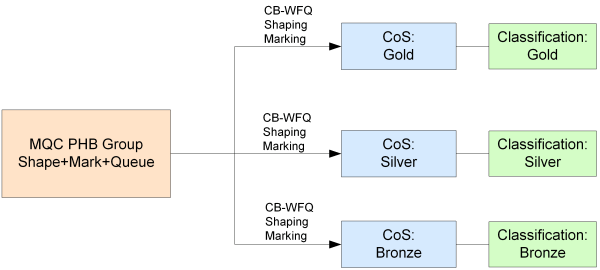
See "Defining Standard Per Hop Behavior Groups" for information on defining standard PHB groups. See "Implementing and Managing Per Hop Behavior Groups" for details on implementing and managing PHB groups.MQC PHB groups allow you to implement Cisco's simplified configuration of policy mechanisms and actions for traffic queuing, shaping, policing, congestion avoidance and re-marking on the interfaces of Cisco routers and switches. You can specify several different QoS mechanisms for different classes of service associated with the same MQC PHB group. An MQC PHB group defines the QoS policy that may be used at various points in the network. For example, an MQC PHB group might be used to manage the traffic going into the core network or to maintain the prioritization set up at the network edge throughout the core network.An MQC PHB group may be applied to one or more classes of service that are based on a classification or classification group. The classification may be defined by factors such as source and/or destination IP address or account and traffic type. A number of classes of service may be linked to an MQC PHB group and one or more different mechanisms applied to each one. Figure 7-1 gives an example.
Within the MQC PHB group definition, you can specify the order in which packets are evaluated against each CoS's match criteria to ensure that packets have the correct mechanism applied to them.
See "Nesting MQC PHB Groups" for information on nesting MQC PHB groups.
An MQC PHB group is configured as a policy map and implemented at an interface as a service policy.
An MQC PHB group can be applied to a network component such as an interface or a VC endpoint, a customer, site or VPN.
The following traffic management mechanisms can be implemented within an MQC PHB group and applied to traffic by class of service:
Low Latency Queuing (LLQ) – assigns a traffic class to a strict priority queue with a guaranteed maximum bandwidth during congestion
Class-based Weighted Fair Queuing (CB-WFQ) – assigns a traffic class to a queue with a priority based on a guaranteed minimum bandwidth during congestion
Class-based Policing – specifies and enforces conditions that define the maximum inbound and outbound bandwidth of a traffic class, packets that exceed the conditions can be dropped or re-marked
Class-based Shaping – specifies and constrains the maximum outbound bandwidth of a traffic class, outbound packets that exceed the conditions are delayed
Class-based Marking – marks packets to allocate a priority status or class
Congestion avoidance (Queue limit and/or WRED) – defines how packets are discarded during congestion
This section outlines the points you need to consider before setting up an MQC PHB group.
The choice of which QoS action to use depends on the QoS policy you want to implement and the capabilities of the router. The available techniques are often specific to the device type, operating system and interface. You may find that some QoS mechanisms can only be implemented on some devices using standard PHB groups. We recommend you consult Cisco's documentation for your specific device. (MQC PHBs are specific to Cisco devices.)
IP Service Activator reports the capabilities of each interface and you should ensure that a QoS action is supported before attempting to configure it. For information on checking an interface's capabilities, see IP Service Activator User's Guide. For more information about supported capabilities, consult the router documentation.
Before creating an MQC PHB group, you need to ensure you have specified the classification parameters for identifying traffic by setting up classes of service. MQC PHB groups operate on one or more classes of service defined by a classification or classification group. See "Setting Up a Classification" for information on defining a classification or classification group. See "Setting Up Traffic Types" for information on defining traffic types.
Note:
You can associate a CoS defined by a classification or classification group and/or a packet marking with an MQC PHB group. However, the MQC PHB group only operates on the traffic defined by a classification or classification group – packet markings are ignored. If you wish to define a traffic class that is characterized by a packet marking, you must create a packet marking traffic type and associate it with a classification.Before setting up MQC PHB groups, you need to know the capabilities of the policy targets to which you intend to apply policy. Check the Capabilities property page on relevant interfaces if necessary.
MQC PHB groups are implemented on the inbound and/or outbound interfaces of the routers to which they are applied. They are created as templates either within a domain or at device level. If created at the domain level, they are applied to various points throughout the network through inheritance so that they are applied to interfaces tagged with the appropriate role. However, an MQC PHB created at device level will apply only to that device's interfaces.
A system of inheritance applies – see "Policy Inheritance" for more information.
The higher the number of devices encompassed by the scope of the MQC PHB, the higher the computational load. It is recommended that you apply MQC PHBs at as close a level to the objects to which they apply. For example, if an MQC PHB is intended to apply to only one device, apply it at that device, rather than at the domain level. You can apply the same MQC PHB in more than one place as needed.
If an MQC PHB group applies to all devices and interfaces that share the same role it can be applied to the root level network and will automatically apply to all relevant interfaces throughout the network.
Note:
IP Service Activator applies only one concrete MQC PHB group to an interface. If you apply an MQC PHB group to the root level network, a concrete MQC PHB group is only created on an interface tagged with the appropriate role if there is no concrete MQC PHB group already installed on that interface. However, a concrete standard PHB group that configures FRTS or ATM traffic shaping can be installed on an interface that has a concrete MQC PHB group that is configured with other QoS mechanisms.Every MQC PHB group must have a device and interface role associated with it. The roles you associate with an MQC PHB group specify to which policy targets the queuing mechanism will apply.
Depending on the roles that you assign to policy targets, it is possible to apply policy only at very specific points in the network. For example, you can apply a role to a sub-interface independent of its parent interface. By associating an MQC PHB group with the sub-interface role, you can apply a QoS policy only at the sub-interface.
See "Using Roles in Policy Elements" for information on using roles.
Note:
When you create an MQC PHB group there are no policy roles associated with it by default. You must associate both a device and an interface role for the MQC PHB group's configuration to be applied at the appropriate points in the network. If either the device or interface role are not specified, no configuration will be applied.You can set up and apply MQC PHB groups as two separate operations or as one combined operation just as you can with PHB groups.
See "Setup and Application of PHB and MQC PHB Groups as Separate Operations" and "Setup and Application of PHB and MQC PHB Groups as a Combined Single Operation" for more information.
To set up an MQC PHB group:
Do one of the following:
On the Policy tab, select the MQC PHB Groups folder.
Select a target object — a network component, customer, site or VPN.
Right-click on the folder or target object and select Add MQC PHB Group from the pop-up menu.
The MQC PHB Group dialog box opens.
Enter values including Name, Configured Name, Description, and Direction.
Select a CoS so that it is highlighted and its check box is checked.
Select one or several QoS actions that you want to associate with the selected CoS including LLQ, Default WFQ, CB-WFQ, SR Police, TR Police, Shape, Mark, Congestion, Nest, RTP Compression
Note:
See MQC PHB QoS Action Combinations in IP Service Activator online Help for a table indicating which combinations of QoS actions are allowed.Repeat steps 4 to 6 for each CoS that you want to use.
Click the Apply button to apply the changes.
To remove all QoS actions associated with a CoS, click on the CoS to clear its check box.
Select the Role property page and select the device and interface roles to which the MQC PHB group applies.
Note:
You must specify both a device and an interface role. The system-defined Any Role can be used to apply the MQC PHB group to any device or interface tagged with a role. See "Using Roles in MQC PHB Groups" for more information.Select the appropriate property page(s), depending on the QoS actions selected, and set the appropriate parameters. For details of configuring each QoS action, see the appropriate description:
Matching – "Specifying Evaluation Order"
Policing – "Setting Up Class-Based Policing"
Policing action – "Setting Up a Policing Action"
Shaping – "Setting Up Class-Based Shaping"
Marking – "Setting Up Class-Based Marking"
Congestion avoidance – "Setting Up Congestion Avoidance"
Nesting – "Nesting MQC PHB Groups"
RTP compression – "RTP Header Compression"
Click OK.
The classes of service that are associated with an MQC PHB group are listed on the MQC PHB group's Classify property page. The order in which these appear is significant. The order can be changed using the controls in the MQC Order pane.
The position of a CoS in the list can affect which QoS actions are applied to a packet.
Packets are evaluated against the classes of service listed in the MQC Order pane in sequence. When a packet matches a class of service, the appropriate QoS actions are applied and no further matching is performed.
For example, Bronze and Gold classes of service may include the same destination address in their match criteria but have different QoS actions applied to them. They are listed in the order shown above. If both CoS's match criteria is Match Any, a packet with the relevant destination address will be matched against the Bronze CoS and no further evaluations made. The packet therefore only has the QoS actions applied to it that have been defined for the Bronze CoS, and is never evaluated against the Gold CoS.
Note:
The match criteria for a CoS is defined by the classification or classification group that is linked to the CoS. See "Setting Up a Classification" for information on defining a classification or classification group.To specify match order:
Select the Classify property page in the MQC PHB Group dialog box.
All classes of service that you selected on the PHB Group page are listed in the MQC Order list.
If required, change the position of a CoS in the MQC Order list by selecting a CoS and clicking the up or down arrows to move it up or down the list.
Save your settings by clicking Apply.
Re-ordering classes within IP Service Activator policies sends the correct configuration to the router, but some Cisco IOSs do not show the correct order on subsequent 'show run' commands. The router does not return any errors. There is no indication that the configuration has not been accepted by the router.
For problematic IOSs, the best work-around is to unlink the entire policy map, re-order the classes and then re-link the policy map. This will ensure that the correct ordering is applied to the router.
The following IOSs have been tested:
You use Low Latency Queuing (LLQ) to assign a strict priority to a CoS to allow delay-sensitive traffic to be given priority over less delay-sensitive traffic during congestion.
The operation of LLQ is identical to Class-Based Weighted Fair Queuing (CB-WFQ) except that LLQ has a strict priority queue.
You allocate a guaranteed bandwidth - a proportion of the output interface bandwidth - to one or more classes of service. When congestion occurs, each traffic flow is placed in its own queue. If there is only one flow of a particular CoS, it will be allocated all of the user-specified bandwidth for that CoS. If there are several flows of the same CoS, each flow queue is allocated an equal proportion of the user-specified bandwidth for that CoS. For example, if a CoS is allocated 60% of the output interface bandwidth, and there are three flows of the same CoS, each flow queue is allocated 20% of the output interface bandwidth.
During congestion, each queue is serviced in turn by a scheduling mechanism that forwards a number of bits from each packet in proportion to the queue's allocated bandwidth. For example, if there are two CoS queues allocated bandwidth of 40% and 20%, each time a queue is serviced, twice as many bits are taken from a packet in the CoS queue allocated 40% bandwidth than bits taken from a packet in the CoS queue allocated 20% bandwidth.
If a CoS is not using its allocated bandwidth, the unused bandwidth is shared by the other classes of service.
During congestion, packets belonging to a CoS that is assigned LLQ are always allowed to be transmitted before packets of a CoS that is assigned CB-WFQ. However, any incoming packets of a traffic class assigned LLQ that exceed the allocated bandwidth will be dropped.
This allows you to configure multiple priority queues for multiple traffic classes by specifying a different priority level for each of the traffic classes in a single service policy map. You can configure multiple service policy maps per router. Having multiple priority queues enables the router to place delay-sensitive traffic, for example, voice traffic, on the outbound link, before delay-insensitive traffic. As a result, high priority traffic receives the lowest latency possible on the router.
In the MQCPHB Group object, LLQ bandwidth type holds a value for representing priority levels. The actual weight attribute of the MQCPHB holds the value of ”level” (valid range of 1 to 4; 1 being the highest priority and 4 being the lowest priority) when the bandwidth type is set to ”level”.
Restrictions and conditions for using multi-level priority queues:
The bandwidth and priority level commands cannot be used in the same class, within the same policy map. These commands can be used in the same policy map, however.
The shape and priority level commands cannot be used in the same class, within the same policy map. These commands can be used in the same policy map.
Within a policy map, you can give one or more classes priority status. The router associates a single priority queue with all of the traffic enabled with the same priority level and services the high level priority queues until empty before servicing the next level priority queues and non-priority queues.
You cannot specify the same priority level for two different classes in the same policy map.
You cannot specify the priority command and the priority level command for two different classes in the same policy map. For example, you cannot specify the priority bandwidth-kbps or priority percent percentage command and the priority level command for different classes.
When the priority level command is configured with a specific level of priority service, the queue-limit and random-detect commands can be used if only a single class at that level of priority is configured.
You cannot configure the default queue as a priority queue at any priority level.
To convert a single-level (flat) service policy with multiple priority queuing configured to a hierarchical multi-level priority queuing service policy, you must first detach the flat service policy from the interface using the no service-policy command, and then add a child policy map to it.
For complete dialog box and property page descriptions, refer to IP Service Activator online Help.
To set up LLQ:
Select the Queue property page in the MQC PHB Group dialog box.
The classes of service that you selected with LLQ on the PHB Group page appear in the QoS Queue area.
Select a CoS and set the following parameters.
Select or clear the check box Maximum reserved bandwidth to enable/or disable this capability. If enabled specify a new value if required. Cisco devices have a default maximum reserve bandwidth value of 75 percent that is designed to leave sufficient bandwidth for overhead traffic. You can alter this by entering a percentage value.
Select a bandwidth option from the Interpret LLQ Weight as list (Absolute Bandwidth, Percentage of Bandwidth, Percentage of Remaining, Default, Level).
Specify the Queue Weight or Level value.
If you are changing the settings of several classes of service in the MQC PHB group, use the Modify button to apply the changes to each CoS.
Specify a value in LLQ burst in bytes. Select Device default to specify the default value for that particular device.
Specify the Fair-queue values to configure fair-queuing.
Select the next CoS in the list and repeat steps 3 to 7.
Save your settings by clicking Apply.
Use Class-Based Weighted Fair Queuing to assign a priority to a CoS based on bandwidth.
You allocate a minimum bandwidth - a proportion of the output interface bandwidth - to one or more classes of service. When congestion occurs, each traffic flow is placed in its own queue. If there is only one flow of a particular CoS, it will be allocated all of the user-specified bandwidth for that CoS. If there are several flows of the same CoS, each flow queue is allocated an equal proportion of the user-specified bandwidth for that CoS. For example, if a CoS is allocated 60% of the output interface bandwidth, and there are three flows of the same CoS, each flow queue is allocated 20% of the output interface bandwidth.
During congestion, each queue is serviced in turn by a scheduling mechanism that forwards a number of bits from each packet in proportion to the queue's allocated bandwidth. For example, if there are two CoS queues allocated bandwidth of 40% and 20%, each time a queue is serviced, twice as many bits are taken from a packet in the CoS queue allocated 40% bandwidth than bits taken from a packet in the CoS queue allocated 20% bandwidth.
If a CoS is not using its allocated bandwidth, the unused bandwidth is shared by the other classes of service.
The operation of CB-WFQ configured using MQC PHB and standard PHB groups is identical.
For complete dialog box and property page descriptions, refer to IP Service Activator online Help.
To set up CB-WFQ:
Select the Queue property page in the MQC PHB Group dialog box.
The classes of service that you selected with CBWFQ on the PHB Group property page appear in the QoS Queue area.
Select a CoS and set the required parameters.
Select a bandwidth option from the Interpret CBWFQ Weight as: list (Absolute Bandwidth, Percentage of Bandwidth, Percentage of Remaining).
Specify the Queue Weight value.
If you are changing the settings of several classes of service in the MQC PHB group, use the modify button to apply the changes to each CoS.
Specify the Fair-queue values to configure fair-queuing.
Select the next CoS in the list and repeat steps 3 to 4.
Save your settings by clicking Apply.
You can use class-based policing to specify and enforce the maximum bandwidth allocated to a specified traffic class transmitted from or received by an interface. Bandwidth is enforced by either dropping or re-marking packets that exceed and/or violate their user-specified conditions. Packets are dropped less aggressively by allowing packets that occasionally exceed the committed information rate as bursts to be transmitted if those burst sizes are within the user-specified conditions.
You specify the maximum rate and burst size(s) that define the conditions to which a packet is required to conform. These values represent the policing profile of the CoS and are specified on the Police property page.
For single rate policing, a conform condition indicates that a packet stream's information rate is within the specified Committed Information Rate (CIR). An exceed condition indicates that a packet stream's information rate is above the specified CIR. A violate condition indicates that a packet stream's burst size is above the specified Committed Burst Size (CBS) and Excess Burst Size (EBS).
For two-rate policing, a conform condition indicates that a packet stream's information rate is within the specified CIR and Peak Information Rate (PIR). An exceed condition indicates that a packet stream's information rate is within the specified PIR but above the specified CIR. A violate condition indicates that a packet stream's PIR is above the specified PIR.
The two-rate (three-color marker) policer improves bandwidth management by allowing you to police traffic streams according to two separate rates. Unlike the single-rate policer, which allows you to manage bandwidth by setting the excess burst size (be), the two-rate policer allows management of bandwidth by setting the Committed Information Rate (CIR) and the Peak Information Rate (PIR). The three-color marker distinguishes between the nonconforming traffic that occasionally bursts a certain number of bytes more than the CIR and violating traffic that continually violates the PIR allowance. Applications can use the three-color marker to provide three service levels: guaranteed, best effort, and deny. The three-color marker is useful in marking packets in a packet stream with different, decreasing levels of assurances (either absolute or relative).
You can specify the actions performed on packets that conform, exceed or violate specified conditions on the Police Action property page.
The following steps are required to configure class-based policing using an MQC PHB group:
Set up a policing profile for a CoS on the Police property page of an MQC PHB Group dialog box.
Set up policing actions for conform, exceed and violate conditions on the Policing Action property page of a PHB Policing Action dialog box.
Associate policing actions with a CoS on the Police Action property page of the MQC PHB Group dialog box.
Note:
Policing actions can be set up before setting up policing profilesFor complete dialog box and property page descriptions, refer to IP Service Activator online Help.
Single rate class-based policing measures bandwidth conformance of traffic based on its Committed Information Rate, Committed Burst Size and Excess Burst Size.
To set up single rate class-based policing:
Select the Police property page in the MQC PHB Group dialog box.
The classes of service that you selected with SR Police on the PHB Group property page appear in the QoS Policing area.
Select a CoS so that it is highlighted.
Specify values fields including CIR, CBS, and EBS.
Rate Type: Selects the policing type. If Absolute is chosen, the additional controls express rates in absolute terms. If Percent is chosen, CIR express a rate in terms of the percentage of available bandwidth. CBS and EBS are expressed in milliseconds (ms) with a valid range of 1 to 2000.
CIR:
Absolute-based: Committed Information Rate in bits/s. Range is 8000 (8 kbits/s) to 4000000 (i.e. 8 kbits/s - 4000 Mbits/s). Default is 8000.
Percentage-based: CIR as a percentage of the interface's bandwidth. Default is 1. Range is 1 to 100%.
CBS:
Absolute-based: Committed Burst Size in bytes. Range 1 kbytes to 512 Mbytes. Default is 1 kbyte.
Percentage-based: Committed Burst Size expressed in ms.
Default: When selected, IP Service Activator defers to the device to set the actual value used for CBS. This can vary from device to device. Also, disables the EBS fields.
When cleared, you can specify a value for CBS.
EBS:
Absolute-based: For Single Rate policing only, Excess Burst Size in bytes. Range is 1 kbyte to 512 Mbytes, the default is 1 kbyte.
Percentage-based: Excess Burst Size expressed in ms.
Default: When selected, IP Service Activator defers to the device to set the actual value used for EBS. This can vary from device to device. When cleared, you can specify a value for EBS.
The following options, when added by the user, provide the default value in the case that the Default check box is checked. For complete details on options, refer to IP Service Activator Cisco IOS Cartridge Guide.
Percent:
cartridge.cisco.qos.policymap.police.percent.defaultCBSValue(Default -1)
cartridge.cisco.qos.policymap.police.percent.defaultEBSValue  (Default -1)
Absolute:
cartridge.cisco.qos.policymap.police.defaultCBSValue (Default -1)
cartridge.cisco.qos.policymap.police.defaultEBSValue (Default -1)
Aggregate policer name: Select to activate aggregate policing and specify the aggregate policer name in the text box.
If you are changing the settings of several classes of service in the MQC PHB group, use the modify button to apply the changes to each CoS.
Select the next CoS in the list and repeat step 3.
Save your settings by clicking Apply.
Two rate class-based policing measures bandwidth conformance of traffic based on its Committed Information Rate, Committed Burst Size, Peak Information Rate and Peak Burst Size.
To set up two rate class-based policing:
Select the Police property page in the MQC PHB Group dialog box.
The classes of service that you selected with TR Police on the PHB Group property page appear in the QoS Policing area.
Select a CoS so that it is highlighted.
Specify values including: CIR, CBS, PIR and PBS.
Rate Type: Selects the policing type. If Absolute is chosen, the additional controls express rates in absolute terms. If Percent is chosen, CIR and PIR express a rate in terms of the percentage of available bandwidth. CBS and EBS are expressed in milliseconds (ms) with a valid range of 1 to 2000. The PIR value must be equal to or larger than the CIR value.
CIR:
Absolute-based: Committed Information Rate in bits/s. Range is 8000 (8 kbits/s) to 4000000 (i.e. 8 kbits/s - 4000 Mbits/s). Default is 8000.
Percentage-based: CIR as a percentage of the interface's bandwidth. Default is 1. Range is 1 to 100%.
CBS:
Absolute-based: Committed Burst Size in bytes. Range 1 kbytes to 512 Mbytes. Default is 1 kbyte.
Percentage-based: Committed Burst Size expressed in ms.
When cleared, you can specify a value for CBS.
PIR: For Two Rate policing only. Absolute-based: Peak Information Rate in bits/s, in the range 8 kbits/s to 4000 Mbits/s. Default is 8 kbits/sec.
PBS: For Two Rate policing only. Peak Burst Size in bytes, in the range 1 kbyte to 512 Mbytes. Default is 1 kbyte.
If you are changing the settings of several classes of service in the MQC PHB Group, use the modify button to apply the changes to each CoS.
The following command syntax options (singleLine/MultiLine/PercentageSyntax) are available for the police command and the desired syntax can be generated by setting the appropriate options. For complete details on options, see IP Service Activator Cisco IOS Cartridge Guide.
cartridge.cisco.qos.policymap.police.conformAction.isSupported
cartridge.cisco.qos.policymap.police.exceedAction.isSupported
cartridge.cisco.qos.policymap.police.violateAction.isSupported
Select the next CoS in the list and repeat step 3.
Save your settings by clicking Apply.
You can specify the treatment of packets that conform to, or exceed the rate value(s), or violate the burst sizes that are specified for a CoS on the Police property page. You can specify a separate action for each of these three states. For example, you can specify that packets that conform are transmitted, packets that exceed are re-marked and transmitted, and packets that violate are dropped. The re-marked values on the packets determine how they are treated by QoS mechanisms set up on interfaces downstream. An action can implement several types of marking.
A policing action is defined by setting up a PHB Policing Action object which can then be specified as either the conform, exceed or violate action for a CoS on the Police Action property page of the MQC PHB dialog box. You can either use default PHB policing actions or specify your own. A PHB Policing Action can be used by several MQC PHB groups.
For complete dialog box and property page descriptions, refer to IP Service Activator online Help.
To set up a PHB policing action:
On the Policy tab, select the PHB Policing Action folder.
Right-click and select Add PHB Policing Action from the pop-up menu.
The PHB Policing Action dialog box opens.
Enter a Name for the PHB Policing Action.
Select either Drop or Transmit.
If you select Transmit, specify how you want packets to be marked by selecting an action including Set ATM CLP, Set FR DE, Set IP Marking, and Set MPLS Exp. If you do not select a marking, then no marking changes are applied to the packet by the PHB Policing Action. Any original packet markings remain intact.
Save your settings by clicking Apply.
Apply a PHB policing action by associating it with an MQC PHB group.
To associate a policing action with an MQC PHB group:
Select the Police Action property page in the MQC PHB Group dialog box.
The classes of service that you selected with SR Police or TR Police on the PHB Group property page appear in the MQC Policing Action area.
Select a CoS and set the required parameters.
Specify values for Conform Action and Exceed Action.
Default Conform Action transmits packets without re-marking. Default Exceed Action drops packets.
Specify a Violate Action, or None.
Default Violate Action drops packets. If None is selected for two rate policing, the default value for Exceed Action will be used.
If you are changing the settings of several classes of service in the MQC PHB group, use the modify button to apply the changes to each CoS.
Select the next CoS in the list and repeat steps 3 to 4.
Save your settings by clicking Apply.
Your selections for each CoS appear in the MQC Policing Action area.
You use class-based shaping to constrain a traffic class to the committed information rate (CIR) and to delay outbound packets that exceed the CIR by placing them in a queue.
Class-based shaping allows you to configure the following:
Average rate traffic shaping – limits the traffic rate to the CIR (on non-Frame Relay interfaces only).
Peak rate traffic shaping – allows traffic rate bursts above the CIR if extra network bandwidth is available, packets may be dropped if network congestion occurs (on non-Frame Relay interfaces only).
Adaptive generic traffic shaping for Frame Relay – uses the Backward Explicit Network Congestion Notification (BECN) to estimate the available bandwidth and adjust the transmission rate accordingly. BECN signals may also be reflected as Forward Explicit network Congestion Notifications (FECN).
CB-WFQ inside GTS – places a packet that exceeds the shape parameters in a queue whose priority is based on bandwidth allocated to the CoS to which the packet belongs. CB-WFQ is configured on the Queue property page.
For complete dialog box and property page descriptions, refer to IP Service Activator online Help. For detailed information related to traffic shaping support, refer to IP Service Activator Cisco IOS Cartridge Guide.
Average or peak rate traffic shaping can be configured on non-Frame Relay interfaces only.
To set up average or peak rate traffic shaping:
Select the Shape property page on the MQC PHB Group dialog box.
The classes of service that you selected with Shape on the PHB Group property page appear in the MQC Shaping area.
Select a CoS from the MQC Shaping area and set the required parameters.
Select either Shape Average or Shape Peak.
Specify values including CIR, Bc, and Be.
If you are changing the settings of several classes of service in the MQC PHB group, use the Modify button to apply the changes to each CoS.
Select the next CoS in the list and repeat steps 3 to 4.
Specify Number of buffers. Select Device default to specify the default value for that particular device.
Save your settings by clicking Apply.
In addition to average or peak rate shaping, you can configure BECN and/or FECN adaptive shaping on Frame Relay interfaces.
To set up adaptive generic traffic shaping:
Select the Shape property page on the MQC PHB Group dialog box.
The classes of service that you selected with Shape on the PHB Group property page appear in the MQC Shaping area.
Deselect Default Shaping and select either Shape Average or Shape Peak.
Specify values including CIR, Bc, and Be.
Specify Number of buffers. Select Device default to specify the default value for that particular device.
Select the FR Extension check box.
Select BECN Adapt and/or FECN Adapt.
Enter a minimum value for CIR in the Min CIR field.
Select the BECN Adapt check box if you want to monitor for Frame Relay frames that have the BECN bit set.
Select the FECN Adapt check box if you want to monitor for Frame Relay frames that have the FECN bit set.
If you are changing the settings of several classes of service in the MQC PHB group, use the Modify button to apply the changes to each CoS.
For each CoS to which you wish to apply adaptive generic traffic shaping, repeat steps 2 to 8.
Your selections for each CoS appear in the MQC Shaping area.
Save your settings by clicking Apply.
Class-based shaping can be used in conjunction with CB-WFQ. This allows a packet that exceeds the shape parameters to be placed in a queue whose priority and bandwidth allocation is defined by the packet's CoS.
To set up CB-WFQ within Generic Traffic Shaping (GTS):
In the MQC PHB Group dialog box, select the PHB Group property page.
Select a CoS to which you want to apply CB-WFQ within GTS.
Select CBWFQ and Shape.
Repeat steps 2 and 3 for each CoS to which you want to apply CB-WFQ within GTS.
Select the Queue page.
For each CoS, set up CB-WFQ as described in "Setting Up Class-Based Weighted Fair Queuing".
Select the Shape property page.
For each CoS, set up GTS as described in "Setting Up Class-Based Shaping".
You can apply basic traffic shaping to Cisco 10000 devices, based on the CIR value only.
To set up basic traffic shaping:
Select the Shape property page on the MQC PHB Group dialog box.
The classes of service that you selected with Shape on the PHB Group property page appear in the MQC Shaping area
Select a CoS and select Default Shaping and specify a value in the CIR field.
Select the next CoS in the list and repeat step 2.
Save your settings by clicking Apply.
You can use class-based marking to mark packets so that they belong to a particular traffic class which can affect how the packets will be managed by QoS policies at other interfaces in the traffic path.
To set up class-based marking:
Select the Mark property page in the MQC PHB Group dialog box.
The classes of service that you selected with Mark on the PHB Group property page appear in the MQC Mark area.
Select a CoS.
Select marking types including Set IP Marking, MPLS Exp., Set FR DE, Set ATM CLP, Discard Class, Set Trust Type, COS, and COS Inner.
If you are changing the settings of several classes of service in the MQC PHB group, use the Modify button to apply the changes to each CoS.
Select the next CoS in the list and repeat step 3.
Save your settings by clicking Apply.
Use congestion avoidance to specify how packets are discarded when congestion occurs. During congestion, packets are queued according to their CoS. For each CoS you can specify:
Queue limit – the maximum number of packets allowed in the queue
and/or:
WRED – Weighted Random Early Detection
Queue limit allows you to specify the maximum number of packets allowed in the queue. If the number of packets reaches the maximum number defined, any additional packets are dropped.
WRED is a congestion avoidance mechanism that drops packets at a specified threshold based on a calculated queue size. You set up WRED parameters on the WRED properties property page in a standard PHB group.
Before you can apply queue limit and/or WRED to a CoS, it must be identified with WRED-compliant packet marking and one of the following:
Bandwidth allocated on the CBWFQ property page
Bit rate specified on the Shape property page
The default CoS does not need to be assigned CB-WFQ or Shape actions, and can be classified with either WRED-compliant packet marking or source/destination IP address or protocol.
A queue limit can be applied to the default class of service for devices that support this. However, at least one class in the policy map must have a queuing feature, when a queue-limit is applied to the default class of service.
For complete dialog box and property page descriptions, refer to IP Service Activator online Help.
To set up congestion avoidance:
Select the Congestion property page in the MQC PHB Group dialog box.
The classes of service that you selected with Congestion on the PHB Group property page appear in the MQC Congestion area.
Select a CoS.
To specify a Queue Limit, select either Default or Value.
From the WRED Strategy list select one of None, Device Default, or Name of a standard PHB group.
If you are changing the settings of several classes of service in the MQC PHB group, use the Modify button to apply the changes to each CoS.
Select the next CoS in the list and repeat steps 3 to 4.
Save your settings by clicking Apply.
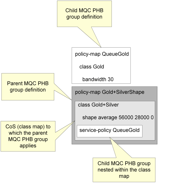
One MQC PHB group may be nested inside another MQC PHB group. This provides a method of applying a policy to a broad range of traffic, defined by the parent MQC PHB group, and another to a subset of that range, defined by the child MQC PHB group. For example, a single shaping policy may be applied to all traffic on an interface by a parent MQC PHB group, while the child applies a queuing policy to one or more classes of service. The resulting configuration is referred to by Cisco as a hierarchical service policy.
Multiple levels of nesting of MQC PHB groups are allowed.
A child MQC PHB group may be nested for a CoS to which Policing, Shaping, CB- WFQ or LLQ is applied. The method for nesting MQC PHB groups is:
Create the child MQC PHB group.
The child MQC PHB group defines Policing, Shaping or CB-WFQ parameters for a subset of traffic handled by an interface – for example, Gold traffic.
Create the parent MQC PHB group.
The parent MQC PHB group defines Policing, Shaping or CB-WFQ parameters for a broader range of traffic handled by an interface – for example, Gold and Silver traffic – and specifies a child MQC PHB group to nest for each CoS.
At command level, an MQC PHB group is configured as a policy map, and a class of service is configured as a class map. Nesting places a policy map (a child MQC PHB group) within a class map (CoS) that is part of another policy map (a parent MQC PHB group).
This is illustrated in Figure 7-2.
To nest MQC PHB groups:
Select the Nest tab.
The classes of service that you selected with Nest and any combination of Shape, SR/TR Police or CBWFQ on the PHB Group property page appear in the MQC Nesting area.
Select a CoS in the MQC Nesting area of the parent MQC PHB group.
Select the child MQC PHB group from the Nest drop down combo box.
If you are nesting several MQC PHB groups, click the modify button to apply each selection.
The name of the child MQC PHB group appears in the Nest column next to the selected CoS in the MQC Nesting area to indicate that the child policy map is nested within the selected class map.
Save your settings by clicking Apply.
RTP (Real-Time Protocol) and RTCP (Real-Time Control Protocol) header compression is supported on out-going Frame Relay traffic on a per-Class-of-Service basis. It is used on relatively low-speed Frame Relay links to improve latency for Voice-over-IP traffic. For each Class of Service you can specify one nesting.
RTP Header Compression reduces the overhead on each voice packet that traverses the network. The near-constant nature of RTP and RTCP header content permits only the differences to be transmitted.
This feature is enabled in the IP Service Activator GUI by selecting the RTP Compression check box on the MQC PHB Group dialog box while the desired CoS is currently selected in the dialog box.
|
Copyright © 2012, 2013, Oracle and/or its affiliates. All rights reserved. Legal Notices |
|