| Skip Navigation Links | |
| Exit Print View | |

|
Sun Blade X4-2B Service Manual |
Troubleshooting the Server Module
Servicing Server Module Components
Servicing a Storage Drive (CRU)
Identifying Storage Drive Indicators and Mechanical Components
Service Action Required Indicator
Lever and Lever Release Button
Storage Drive Failure and RAID
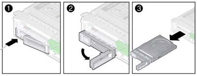
Remove Storage Drive Filler Panels
Insert Storage Drive Filler Panels
DIMM Fault Remind Circuit and ECC Errors
Fault Remind Button and Charge Status Indicator
Inconsistencies Between DIMM Fault LEDs and the BIOS Isolation of Faulty DIMMs
DIMM Population Rules and Guidelines
Detailed Memory Population Rules
Servicing USB Flash Sticks (CRU)
Servicing a Fabric Expansion Module (CRU)
Servicing a RAID Expansion Module (CRU)
Replace a REM Battery on the REM Card
Selecting the Correct Processor Removal/Replacement Tool
Processor Fault Remind Circuit
Fault Remind Button and Charge Status Indicator
Remove a Processor Heat Sink (FRU)
Install a Processor Heat Sink (FRU)
Servicing the Motherboard Assembly (FRU)
Remove Motherboard Assembly Components (FRU)
Install Motherboard Assembly Components (FRU)
Servicing the System Battery (CRU)
Returning the Server Module to Operation
BIOS Power-On Self-Test (POST) Checkpoints
Refer to the OS documentation.
For drive locations on the server module, see Identifying Storage Drives.
Faulty storage drives are identified by lit blue (Ready to Remove) and amber LED status indicators.
For more information, see Identifying Storage Drive Indicators and Mechanical Components.
Caution - Over-temperature condition. Do not operate the server with empty storage device slots. Always insert a filler panel into an empty storage device slot. See Insert Storage Drive Filler Panels. |

Next Steps