| Skip Navigation Links | |
| Exit Print View | |

|
Sun Blade X4-2B Service Manual |
Troubleshooting the Server Module
Servicing Server Module Components
Servicing a Storage Drive (CRU)
Identifying Storage Drive Indicators and Mechanical Components
Service Action Required Indicator
Lever and Lever Release Button
Storage Drive Failure and RAID
Remove Storage Drive Filler Panels
Insert Storage Drive Filler Panels
DIMM Fault Remind Circuit and ECC Errors
Fault Remind Button and Charge Status Indicator
Inconsistencies Between DIMM Fault LEDs and the BIOS Isolation of Faulty DIMMs
DIMM Population Rules and Guidelines
Detailed Memory Population Rules
Servicing USB Flash Sticks (CRU)
Servicing a Fabric Expansion Module (CRU)
Servicing a RAID Expansion Module (CRU)
Replace a REM Battery on the REM Card
Selecting the Correct Processor Removal/Replacement Tool
Processor Fault Remind Circuit
Fault Remind Button and Charge Status Indicator
Remove a Processor Heat Sink (FRU)
Install a Processor Heat Sink (FRU)
Servicing the Motherboard Assembly (FRU)
Remove Motherboard Assembly Components (FRU)
Install Motherboard Assembly Components (FRU)
Servicing the System Battery (CRU)
Returning the Server Module to Operation
BIOS Power-On Self-Test (POST) Checkpoints
The following topics describe the components of the Fault Remind circuitry:

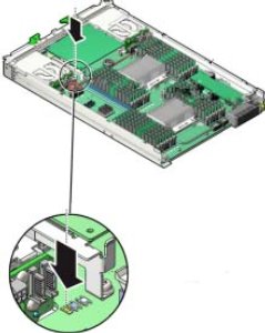
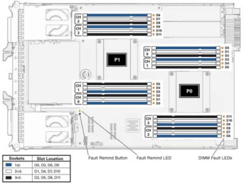
The blue Fault Remind button (SW3001) is located on the motherboard next to the Charge Status indicator (CR3002). The Charge Status indicator indicates the usability of the test circuit. When the Fault Remind button is pressed, the Charge Status indicator, lights green to indicate that there is sufficient voltage present in the Fault Remind circuit to activate the fault indicators. DIMM Fault indicators identify DIMMs in a fault state.
The DIMM Fault indicators are located on the motherboard next to each DIMM slot. The amber indicators light up when the Fault Remind button is pressed and a DIMM fault condition exists.

Related Information:
When a single DIMM is marked as faulty by Oracle ILOM (for example, fault.memory.intel.dimm.training-failed is listed in the SP event log), BIOS might disable the entire memory channel that contains the faulty DIMM as failing, that is, up to three DIMMs. As a result, the memory available to the operating system is reduced. However, when the Fault Remind button is pressed, only the fault status indicator (LED) associated with the faulty DIMM lights. The fault LED for the other DIMM in the memory channel remains off. Therefore, you can correctly identify the faulty DIMM.
When the faulty DIMM is replaced and the DIMM fault is cleared using Oracle ILOM, the memory available to the operating system returns to normal. You can use the Oracle ILOM web interface or the command-line interface (CLI) to manually clear faults. For information on how to use the Oracle ILOM web interface or the CLI to clear server faults, see the Oracle Integrated Lights Out Manager (ILOM) 3.1 Documentation Library at: http://www.oracle.com/goto/ILOM/docs.
The server's processor provides data parity protection on its internal cache memories and error-correction code (ECC) protection. The system can detect the following types of errors: correctable and uncorrectable memory ECC errors and uncorrectable CPU internal errors. Errors are recorded in the Oracle ILOM system event log (SEL).
Advanced ECC corrects up to 4 bits in error on nibble boundaries, as long as they are all in the same DRAM. If a DRAM fails, the DDR3 DIMM continues to function. For instructions for clearing DDR3 DIMM faults, refer to http://www.oracle.com/goto/x86AdminDiag/docs.