JavaScript is required to for searching.
Skip Navigation Links
Exit Print View
Oracle Switch ES1-24

Service Manual

search filter icon
search icon

Document Information

Using This Documentation

Product Notes

Related Documentation

CLI Command Modes

Feedback

Support and Accessibility

Detecting and Managing Faults

Front Panel LEDs

Rear Panel LEDs

Check Switch Status (LEDs)

Sensors Overview

Check Switch Status (Oracle ILOM)

Component Sensor Targets

Motherboard Sensor Targets

Preparing for Service

ESD Precautions

Tools Needed for Service

Replaceable Components

Remove the Front Support and Air Duct

Remove the CMA

Install the CMA

Servicing Power Supplies

Power Off a Power Supply

Remove a Power Supply

Install a Power Supply

Power On a Power Supply

Servicing the Fan Module

Remove the Fan Module

Install the Fan Module

Glossary

Index

Install the CMA


Note - If you are installing the CMA onto a switch with the data cables in the cold aisle, the procedure is the same, however the following illustrations differ slightly from your situation.
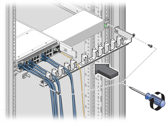
  1. Bring the CMA up from under the cables, and align the CMA to where it installs to the rack slides.
    image:Figure shows installing the CMA.
  2. Using a No. 2 Phillips screwdriver, secure the CMA to the rack with two M6x14 screws.
  3. Organize the cables into the slots of the CMA.
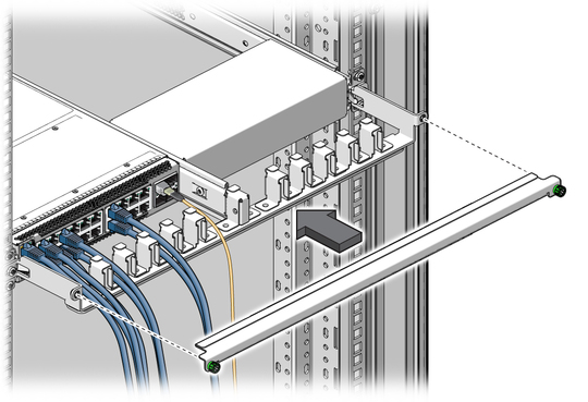
  4. Replace the CMA cover, and tighten the green captive thumbscrews.
    image:Figure shows installing the CMA cover.
Related Information