Oracle® Enterprise Manager Ops Center
Configuring a Secondary Service Domain
12c Release 2 (12.2.2.0.0)
E57844-01
December 2014
This guide provides an end-to-end example for how to use Oracle Enterprise Manager Ops Center.
Introduction
This document focuses on using the latest features introduced in Oracle Enterprise Manager Ops Center 12.2 to create a highly available environment using a dual I/O configuration as well as the application of several best practices.
In earlier versions of Oracle Enterprise Manager Ops Center, it was only possible to create and manage the control domain which owned all the physical I/O devices and also provided virtual devices to the guest domains. It was impossible to configure, deploy, manage, or discover a secondary domain. An advantage of having a secondary service domain and creating a resilient environment is that maintenance on the control domain (such as OS upgrades, patching, and increasing memory) happens without affecting any running guest domains.
This example describes how to use Oracle Enterprise Manager Ops Center 12.2.1 to deploy:
-
A control domain, also referred to as primary domain and denoted as
primarywherever applicable in the Oracle Enterprise Manager Ops Center UI. -
A secondary service domain, also referred to as alternate I/O domain or redundant I/O domain. The secondary service domain is a root domain, that is a domain configured with a PCIe root complex with a configuration similar to the control domain.
-
A high available (HA) guest domain, the guest domain will use services from both, the control domain and secondary service domain for improving resilient.
The scenario in this document uses an Oracle SPARC server and Oracle VM Server for SPARC to create the control domain, the secondary service domain, and the guest domain.
What You Will Need
The following resources are used for this example:
-
A server hosting Oracle Enterprise Manager Ops Center, the Enterprise controller and the co-located Proxy controller.
-
Oracle Enterprise Manager Ops Center 12.2.1 installed. Enterprise Controller (EC) with co-located Proxy Controller (PC), and an embedded database running on Solaris 11.1 SRU 19.6.
-
Oracle Solaris 11 Software Update Library. This example uses Oracle Solaris 11.1 SRU 19.6 content
-
Oracle SPARC T5-2 ILOM discovered and managed in Oracle Enterprise Manager Ops Center.
-
Sun ZFS Storage 7120 appliance discovered in Oracle Enterprise Manager Ops Center.
-
Fiber Channel (FC) LUNs available from the Sun ZFS Storage 7120 appliance.
-
NFS share from the Sun ZFS Storage 7120 appliance.
-
Free IP addresses allocated.
-
VLAN tagged network created in Enterprise Manager Ops Center.
-
Oracle SPARC T5-2 for provisioning Oracle VM for SPARC Server, version 3.1.1. The server requires a free PCIe bus for configuring the secondary service domain.
-
Virtualization Admin, and Profile and Plan Admin role to perform the actions.
Preview of the Configuration for the Resilient Environment
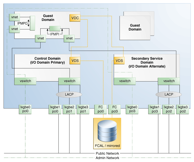
An Oracle SPARC T5-2 Server is used to create the service domains and the HA guest domain. A summary of how the domains and guest will be configured is explained in the following section, followed by a table which includes the PCIe buses used, and then an image depicting the layout.
Due to lab constraints, I/O configuration options were limited; therefore, setting up a best practice environment in all areas was not possible. However, the document mentions areas in which best practices could be applied.
Configuration Summary
The primary and secondary domains will be configured similarly, with:
-
Connections to a Public and an Admin network
-
Link aggregation for the public Network
-
Connections to an Sun 7120 Storage Appliance
-
Oracle Solaris 11.1 SRU 19.6 operating system (OS)
-
Oracle VM Server for SPARC 3.1.1
-
4 whole-core CPUs for the control domain, and 2 whole-cores CPUs for the secondary domain
-
16 GB of memory for the control domain and 4GB of memory for the secondary domain.
Each domain will have access to different PCIe buses for resilience.
For best practice, consider having multipathed LUNs from the storage to the primary and secondary domains.
The guest domain will have:
-
Two network connections for the public network, one from each domain
-
Two network connections for the admin network, one from each domain
-
Redundant storage I/O paths provided by primary and secondary domains
-
Oracle Solaris s11.1 SRU 19.6 operating system
-
4 core CPUs
-
4 GB of memory
The following table shows how PCIe buses are used for each domain:
| Domain | Configuration | Network | Storage |
|---|---|---|---|
| Control domain | Oracle Solaris 11 SRU 19.6
4 CPUs 16 GB of memory |
4 Ethernet connections:
ixgbe0 (pci0) connected to admin network. ixgbe1(pci0), ixgbe2(pci1), and ixgbe3(pci1) connected to the public network, all aggregated. |
FC LUN (pci0) provided by a Sun ZFS Storage 7120 appliance |
| Secondary service domain | Oracle Solaris 11 SRU 19.6
2 CPUs 4 GB of memory |
4 Ethernet connections:
ixgbe0 (pci3) connected to admin network. ixgbe1(pci3), ixgbe2(pci2), and ixgbe3(pci2) connected to the public network, all aggregated. |
FC LUN (pci3) provided by a Sun ZFS Storage 7120 storage appliance |
| Guest domain | Oracle Solaris 11 SRU 19.6
4 CPUs 4 GB of memory |
4 virtual network connections:
The admin network has two virtual networks (vnets) one from the control domain and one from the secondary domain which is IP Multipathed (IPMP0). The public network has two network connections, one from the control domain and one from the secondary domain which will be IP Multipathed (IPMP1). |
Redundant I/O paths to virtual disk server in control domain and secondary domain. |
Figure 1 illustrates how the Oracle SPARC server will be configured to allow for resilient logical domains.
Figure 1 Resilient Environment for Logical Domains
Description of "Figure 1 Resilient Environment for Logical Domains"
Steps for Creating the Environment
To following steps define the procedure to create a resilient logical domain environment, each step is discussed in detail:
Configuring and Provisioning the Control Domain
The first domain in Oracle VM Server for SPARC is always the control domain. The main purpose of this domain is to provide an environment where the Oracle VM Server for SPARC Manager runs. It also provides virtual console services as well as virtual services to guest domains.
The following steps define the procedure to successfully configure and provision Oracle VM Server for SPARC 3.1.1 version:
Creating an OS Provisioning Profile
The OS provisioning profile (OSP) allows you to set the operating system parameters, including file system layout, time zones, passwords, and other parameters.
To create the OSP in Oracle Enterprise Manager Ops Center:
-
Select Plan Management section and expand Profiles and Policies in the Navigation pane.
-
Select OS Provisioning profile and click Create Profile in the Actions pane.
-
Enter the following details in the Create OS Profile - OS Provisioning wizard and then click Next to specify the OSP parameters.:
-
Name and description of the profile.
-
Select Oracle VM Server for SPARC as the Subtype.
-
-
Select the following parameters in the Specify OSP Parameters step and then click Next to specify the OS setup:
-
Select the Oracle VM Server for SPARC version along with the required Oracle Solaris 11 OS and SRU. In this example, select the version
Solaris 11.1 SRU 19.6.0 (LDom 3.1.1.0). -
Select
solaris-small-serverfrom the Systems Software Group.
-
-
Retain the default values for the OS setup parameters or edit the language, time zone, and NFS4 Domain values for your environment. Enter the root password and confirm the password. Click Next to specify the user account for Oracle Solaris 11 OS.
You can also choose to select the Manual Net Boot and Save NVRAMRC options. For more information about this, refer to Oracle Enterprise Manager Ops Center Feature Reference Guide.
-
Root login is not enabled in Oracle Solaris 11 OS. Create a user account to SSH to the OS after provisioning. Provide a user name and password for the account.
Click Next to specify whether you want to use iSCSI disks for provisioning Oracle VM Server for SPARC.
-
Do not select the option to use iSCSI disk as this scenario does not involve the use of iSCSI disk for provisioning Oracle VM Server for SPARC.
Click Next to specify the file system layout.
-
Retain the default values for the root (/) and swap file systems. You have the options to change the swap size and add more ZFS file systems.
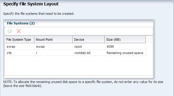
Description of the illustration osp_step6.png
Click Next to specify the name service.
-
If you have a naming service in place, select the appropriate one and provide the setup details. In this example, select None for the naming service.
If you have any naming service in your setup, refer to the help in the wizard or the Oracle Enterprise Manager Ops Center Feature Reference Guide for information about specifying the naming services.
Click Next to view the summary of the parameters selected for the profile.
-
Review the parameters selected for the profile and click Finish to create the OS provisioning profile.
Creating an OS Configuration Profile
The OS configuration profile (OSC) is used to configure the resources for the control domain, like CPU cores, as well as detach unused buses, set network options, and other options.
To create the OSC in Oracle Enterprise Manager Ops Center:
-
Select the Plan Management section in the Navigation pane and expand Profiles and Policies.
-
Select OS Configuration and click Create Profile in the Actions pane.
-
Enter the following details in the Create Profile - OS Configuration wizard:
-
Name and description of the profile.
-
Select Oracle VM Server for SPARC as the Subtype.
Click Next to specify the control domain parameters.
-
-
Specify the resources that you want to assign to the control domain. The remaining resources are available for the logical domains. The following are new additions to the 12.2 version:
-
Allocate CPU resources as Whole Cores. All threads are allocated from the CPU to the control domain.
-
Virtual Disk Server name can be altered from the default.
-
Detach unused buses, PCIe buses that are not required for use by the control domain are unassigned and can be used for other domains.
-
Enable SR-IOV, permits virtual functions to be shared from the PCIe card if the card permits.
In this scenario, select the following configuration parameters for the control domain:
-
Oracle VM Server Version: Select the
Solaris 11.1 SRU 19.6.0 (LDom 3.1.1.0) version to be installed. -
CPU Model: Use Whole-core to allocate the CPU resource in cores.
-
CPU Cores: Enter four CPU core to be allocated to the control domain.
-
Memory: Enter 16 GB as the memory required for control domain.
-
Virtual Console Port Range: Enter the range between 5000 to 6000.
Do not provide any values for Requested Crypto Units and Max CPU Cores. Retain or edit the default name of the virtual disk server. Select the option Detach Unused Buses.
Click Next to specify the OS management details.
-
-
Select the option Enable Multiplexed I/O so that you can associate block storage libraries such as SAN and iSCSI for storage with the control domain.
Click Next to specify the networking details.
-
Select None as the networking option for Oracle VM Server for SPARC.
Click Next to specify the networking details for Oracle VM Server for SPARC.
-
Select the network interface to use for OS provisioning. Select the Controller that hosts the network interfaces and the corresponding network interface. The Address Allocation is Use Static IP by default and cannot be modified.
Select Auto to create a virtual switch automatically for the network connection to the control domain. The virtual switch is created in the default format. For example, the network 192.0.2.0/24, the virtual switch is created as 192.0.2.0_24.
Note:
As Figure 1shows, the networks of the control domain are aggregated. However, as the option Detach Unused Buses is selected, this would mean pci1 would not be owned by the control domain, so aggregation as required (for using pci0 and pci1) is not possible. Aggregation will happen later when pci1 is re-added and owned by the control domain.Click Next to view the summary of the parameters selected for OS configuration.
-
Review the parameters and click Finish to create the OS configuration profile.
Creating the Deployment Plan and Provisioning the Control Domain
The Deployment Plan combines the OSP and OSC to provision and configure the control domain.
To create the deployment plan in Oracle Enterprise Manager Ops Center:
-
Select Plan Management section in the Navigation pane.
-
Expand Deployment Plans and select Provision OS.
-
Click Create Deployment Plan in the Actions pane.
-
Enter the following information for the deployment plan:
-
Name and description for the plan.
-
Select Stop at Failure as the Failure Policy.
-
Select the corresponding OS provisioning and configuration profile created for the control domain.
-
-
Click Save to create the deployment plan.
Once the Deployment plan has been created, the next task is to provision the control domain. To do this selects the ILOM server from the assets menu and select Install Server from the Actions panel. A job will be created, similar to the one below after completing the steps:
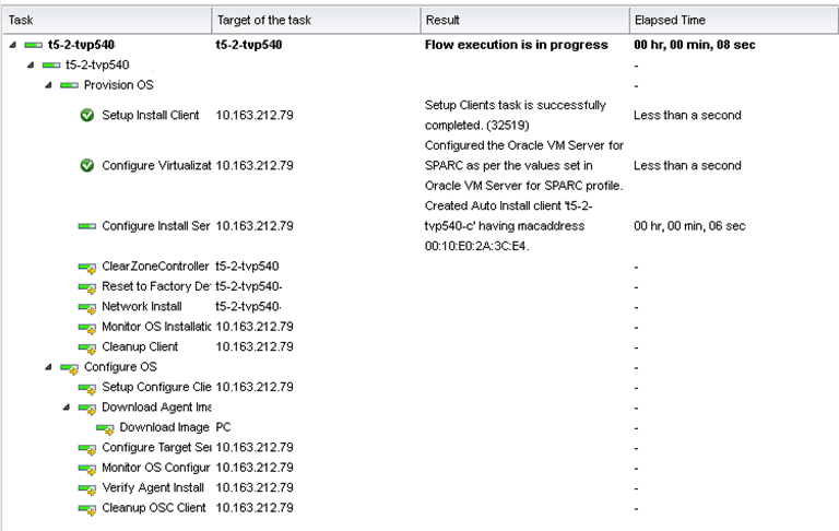
Description of the illustration job_details.png
Once the Provisioning job has completed successfully, check if the parameters have been set. This can be seen from the UI by selecting the Summary tab.
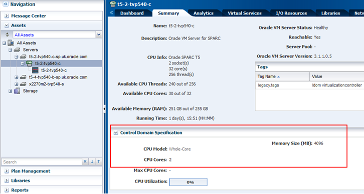
Description of the illustration control_domain_summary.png
Since the option Detach unused buses was selected in the OSC, the control domain only owns the pci0 bus. You can verify it in the UI by selecting the I/O Resources tab, or in the CLI by logging in to the control domain and using the ldm ls-io command. From the CLI the output will look similar to the following:
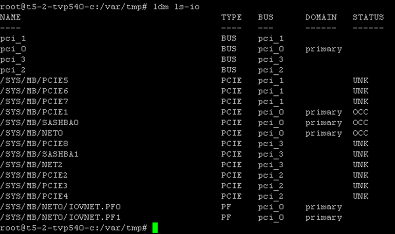
Description of the illustration cli_ldm_lsio.png
As shown above, the control domain now only owns pci_0.
Adding a PCI bus to the Control Domain
As seen in the output generated by the command ldm ls-io, pci1 needs to be added to the control domain, which will provide another network interface and allow network aggregation across the pci0 and pci1 buses.
Currently, the network devices on the control domain are ixgbe2 (net0) and ixgbe3 (net1). You can verify it from the CLI by using the dladm show-phys command.
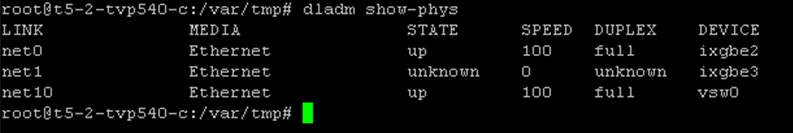
Description of the illustration cli_dlam_showphys.png
The device numbers might seem strange at first, as seeing ixbge0 and ixbge1 would be more logical. The reason for the numbering is because of the way Oracle Solaris maps instance names to physical devices in /etc/path_to_inst. Oracle Solaris keeps a history about all devices and how they are mapped.
PCIe buses cannot be dynamically added to the control domain. Therefore, the control domain is set in delayed reconfiguration mode. In this mode, operation changes take effect after the next reboot.
Certain actions, usually one-time actions, cannot be performed from the UI, such as adding a PCIe bus. These actions need to be performed from the CLI by using ldm commands on the control domain. A new feature in Ops Center 12.1 and above allows using CLI or BUI in parallel to perform administration tasks.
To add a new PCIe bus to the control domain:
-
Initiate the delayed reconfiguration state in the control domain by using the
ldm start-reconfcommand.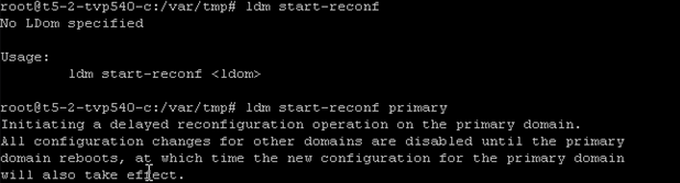
Description of the illustration cli_start_reconf.png
-
Add the PCIe bus to the control domain by using the
ldm add-iopci_1 primary command, in this scenario the PCIe bus name pci1 is added.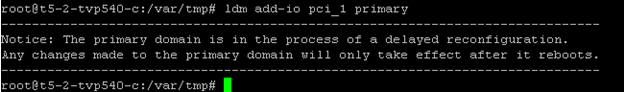
Description of the illustration cli_add-io.png
-
Reboot the primary domain for changes to take effect.
After the reboot, the control domain is now the owner of pci1 and pci0, as shown below.
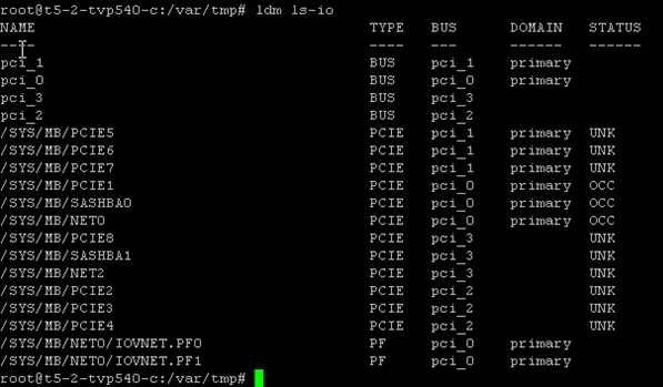
Description of the illustration cli_ls_io.png
The network devices available on the control domain are now xgbe2 (net0), ixgbe3 (net1), xgbe0 (net4), and xgbe1 (net5):
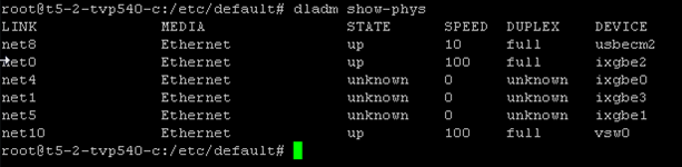
Description of the illustration cli_show-phys2.png
This yields the four network interfaces that are required. In the next step, three of the interfaces for the public network will be aggregated.
Aggregating Networks and Creating a Virtual Switch to the Control Domain
Link aggregation increases bandwidth, provides degradation as failure occurs, and increases availability. In addition, it provides network redundancy by load-balancing traffic across all available links. If a link fails, the system automatically load-balances traffic across all remaining links as specified when creating the policy.
For redundancy, network links are used from the pci0 and pci1 buses. These are aggregated for better throughput and added redundancy.
The following steps define the procedure to create the aggregated links and the virtual switch:
Creating Aggregated Links
To create aggregated link from the UI:
-
Expand Assets in the Navigation pane and select the OS of the control domain.
-
Select the Networks tab in the center pane, then the Link Aggregations sub tab, and click the Create Link Aggregation icon.
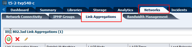
Description of the illustration link_aggregations.png
-
Specify a name for the link aggregation and move the network interfaces to the link aggregation members list, as shown below.
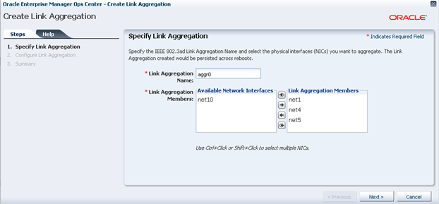
Description of the illustration specify_link_aggregation.png
-
Configure the aggregation links, as shown in the image below.
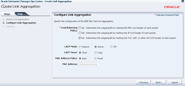
Description of the illustration configure_link_aggregation.png
-
Review the summary and click Finish.
You can use the UI or the command line to confirm that the correct changes have taken place.
From the command line, login to the control domain and run the following command:
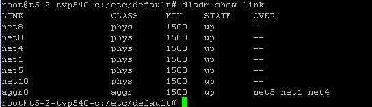
Description of the illustration cli_dlam_showlink.png
As shown in the output above, an aggregated link called aggr0 has been created, consisting of net 1, net 4, and net 5. This information can also be seen from the UI, as depicted in the image below:
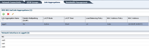
Description of the illustration link_aggregations_added.png
Creating a Virtual Switch
At this stage, a virtual switch (vsw) for the aggregation link aggr0 needs to be created for the control domain. This virtual switch connects the guest domain to the public and admin networks.
To create a virtual switch:
-
Expand Assets in the Navigation pane and select the control domain.
-
Select the Networks tab in the center pane and click Attach Network.
-
Select the public network, in this example is
vlan-1234.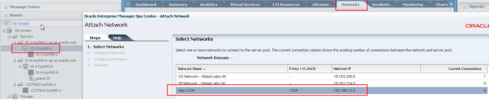
Description of the illustration attach_admin_network.png
-
Configure the aggregation links, as shown in the image below.
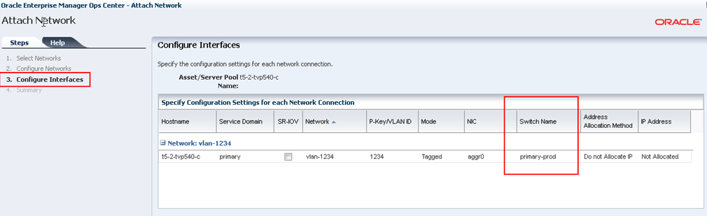
Description of the illustration attach_admin_configureint.png
-
Review the summary and click Finish.
You can use the command line to view the newly created virtual switch for the aggregated links (aggr0) by using the
ldm ls-servicescommand.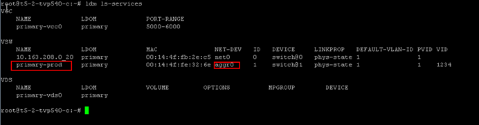
Description of the illustration cli_ldom_lsservices.png
Configuring and Provisioning the Secondary Service Domain
As mentioned before the secondary service domain has various names, such as alternate I/O domain or redundant I/O Domain.
By design, the secondary domain will have some physical I/O devices assigned, which may be a PCIe bus root complex, a PCI device, or a SR-IOV (Single Root I/O Virtualization) virtual function.
Within Oracle Enterprise Manager Ops Center, when creating a secondary domain, the terms physical I/O domain and root domain are used. The physical I/O domain maps PCI device end points, and the root domain maps PCIe buses, which also has an option to create SR-IOV functions.
In this example, a Root Domain is created by assigning PCIe buses. As seen, the Oracle SPARC T5-2 server has two free PCIe buses that have not been assigned to the primary Domain (pci2 and pci3). These PCIe buses are used to create the secondary domain (root domain).
The following steps define the procedure to successfully configure a secondary service domain:
Creating the Logical Domain Profile
To create the secondary service domain in Oracle Enterprise Manager Ops Center, start by creating a Logical Domain Profile.
To create the Logical Domain profile:
-
Select Plan Management section and expand Profiles and Policies in the Navigation pane.
-
Select Logical Domain profile and click Create Profile in the Actions pane.
-
Enter the following details in the Create Profile - Logical Domain wizard and then click Next.
-
Name and description of the profile.
-
Retain the option to create a deployment plan for this profile.
-
Select Root Domain as the Subtype.
-
-
Provide a name for the secondary service domain and click Next.
-
Enter the configuration details for the secondary service domain and click Next. In this example, you use Whole-Core CPU model with 2 CPU cores and 4 GB of memory.
-
Specify the number of PCIe buses to be assigned to the secondary I/O and click Next. In this example, you assign two buses.
-
Select a library to store the metadata and the secondary service domain's storage, then click Next. In this example, select the local filesystem library and enter the disk size as 20 GB.
The metadata is on the local disk,
file://guest.This is fine for the secondary domain as it will not be migrated. Only the logical domains and their guests will get migrated; this makes it mandatory to have the metadata on a shared storage. -
Skip the step to specify networks and click Next. This step is optional for this example.
-
Review the parameters selected for the profile and click Finish to create the profile.
Applying the Logical Domain Profile
To apply the logical domain profile in Oracle Enterprise Manager Ops Center:
-
Select Plan Management section in the Navigation pane and expand Deployment Plans.
-
Expand Create Logical Domains and select the newly create plan from the list.
-
Click Apply Deployment Plan in the Actions pane.
-
In the Select Targets window, select the control domain.
Click Add to Target List to move the selected target Oracle VM Server to the Target List, then click Next.
-
Specify the name for the secondary service domain, then click Next.
-
Select the PCIe buses that will be assigned to the secondary domain and then click Next. In this example, you assign
pci1_3andpci_2.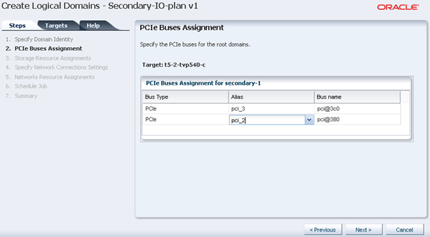
Description of the illustration ldom_pcie_assign.png
-
Retain or edit the default name of the virtual disk server (vds), then click Next.
-
In the profile to create root domain, the network connections details were not provided. Therefore, the Network Connection Settings step and Network Resource Assignments steps are empty. For this example, skip both steps by clicking Next.
-
Schedule the job to run now and click Next.
-
Review the properties and click Apply to apply the deployment plan to create secondary domain.
Once the job completes successfully, you can use the UI or the command line to confirm that the changes.
From the command line, login to the control domain and run the following commands:
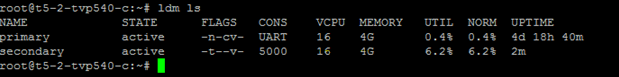
Description of the illustration cli_secondary_ldmls.png
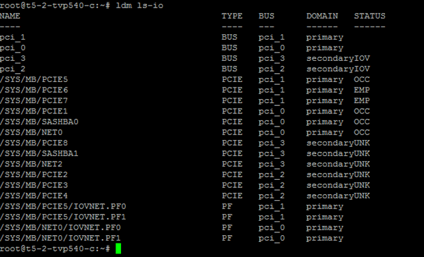
Description of the illustration cli_secondary_ldmlsio.png
From the UI, confirm that the buses have been assigned correctly in the I/O Resources tab of the secondary domain:
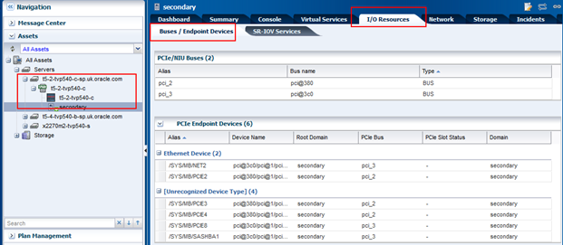
Description of the illustration secondary_ioresources.png
Provisioning the Secondary Domain OS
To provision the operating system to the secondary service domain, you need to create an OS provisioning (OSP) profile, create an OS configuration (OSC) profile, create a deployment plan for the OSP and OSC profiles, and apply the deployment plan to the secondary service domain.
Creating an OS Provisioning Profile
-
Select Plan Management section and expand Profiles and Policies in the Navigation pane.
-
Select OS Provisioning profile and click Create Profile in the Actions pane.
-
Enter the following details in the Create OS Profile - OS Provisioning wizard and then click Next to specify the OSP parameters.:
-
Name and description of the profile.
-
Select Logical Domain as the Subtype.
-
-
Complete the remaining steps according to your requirements. In the Summary screen click Finish to create the OSP profile.
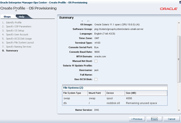
Description of the illustration secondary_osp_profile.png
Creating an OS Configuration Profile
To create the OSC in Oracle Enterprise Manager Ops Center:
-
Select the Plan Management section in the Navigation pane and expand Profiles and Policies.
-
Select OS Configuration and click Create Profile in the Actions pane.
-
Enter the following details in the Create Profile - OS Configuration wizard:
-
Name and description of the profile.
-
Select logical domain as the Subtype.
Click Next to specify the logical domain parameters.
-
-
Complete the remaining steps according to your requirements. In the Summary screen click Finish to create the OSC profile.
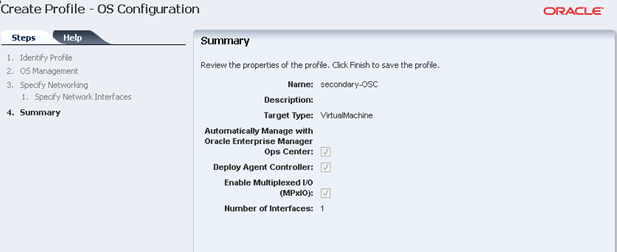
Description of the illustration secondary_osc_profile.png
Creating the Deployment Plan and Provisioning the Secondary Domain OS
To create the deployment plan in Oracle Enterprise Manager Ops Center:
-
Select Plan Management section in the Navigation pane.
-
Expand Deployment Plans and select Provision OS.
-
Click Create Deployment Plan in the Actions pane.
-
Enter the following information for the deployment plan:
-
Name and description for the plan.
-
Select Stop at Failure as the Failure Policy.
-
Select the corresponding OS provisioning and configuration profile created for the secondary service domain.
-
-
Click Save to create the deployment plan.
Once the Deployment plan has been created, the next task is to apply the deployment plan to the secondary service domain.
-
Expand Assets in the Navigation pane and select the control domain.
-
Click Create Logical Domains in the Actions pane.
-
Select the recently created Deployment Plan and complete the Provision OS step.
-
In the Boot Interface Resource Assignment step, make sure that the correct boot interface is selected, as shown below.
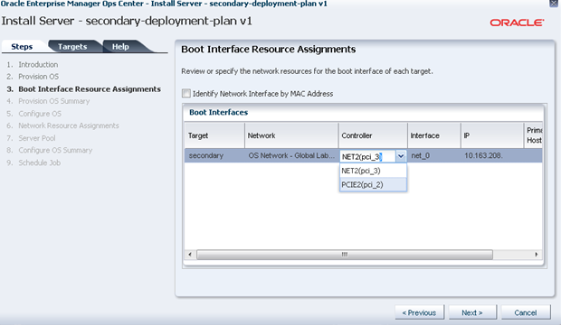
Description of the illustration secondary_install_server.png
-
Complete all other steps as required and then, click Finish. A job, similar to the one depicted below, will run.
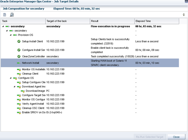
Description of the illustration secondary_install_job.png
It is possible and recommended to view how the install is progressing. To do this, log on the control domain and view the /var/log/vntsd/secondary/console-log file as shown below.
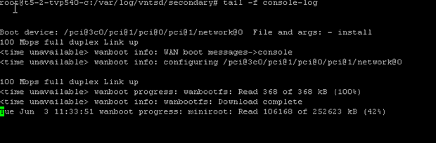
Description of the illustration cli_applyplan_job.png
Once the job has completed successfully, confirm the set-up is correct in the UI or the command line.
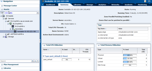
Description of the illustration secondary_plan_results.png
Creating Aggregation Link and Creating Virtual Switches
As with the control domain, the public network for the secondary service domain are aggregated links in order to provide resilience and better throughput.Creating aggregated links in the secondary domain is a similar process to the one used to create those links in the control domain virtual switch (vsw). However, another virtual switch for the admin network needs to be created.
Creating Aggregated Links
To create aggregated link from the UI:
-
Expand Assets in the Navigation pane and select the OS of the secondary domain.
-
Select the Networks tab in the center pane, then the Link Aggregations sub tab, and click the Create Link Aggregation icon.
Description of the illustration link_aggregations.png
-
Specify a name for the link aggregation and move the network interfaces to the link aggregation members list, as shown below.
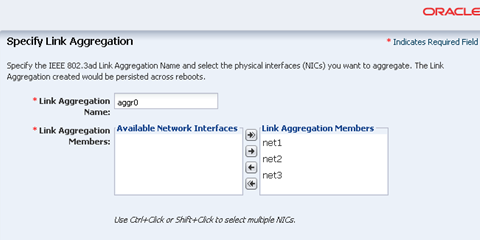
Description of the illustration specify_link_aggregation2.png
-
Configure the aggregation links, as shown in the image below.
Description of the illustration configure_link_aggregation.png
-
Review the summary and click Finish.
You can use the UI or the command line to confirm that the correct changes have taken place.
From the command line, login to the secondary domain and run the following command:
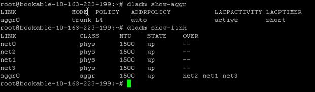
Description of the illustration cli_secondary_aggr.png
As shown in the output above, an aggregated link called aggr0 has been created, consisting of net 1, net 2, and net 3. This information can also be seen from the UI, as shown below:
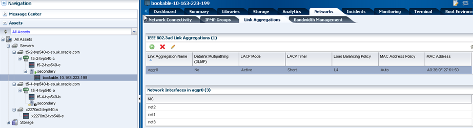
Description of the illustration secondary_aggr.png
Creating a Virtual Switch
The command line output shown below shows that the primary domain has two virtual switches; one from the admin network and another from the public network. The secondary domain, on the other hand, has no virtual switches.
Description of the illustration cli_vsws.png
To create a virtual switch for the admin network:
-
Expand Assets in the Navigation pane and select the control domain that was just created.
-
Select the Networks tab in the center pane and click Attach Network.
-
Select the admin network, in this example is
OS Network.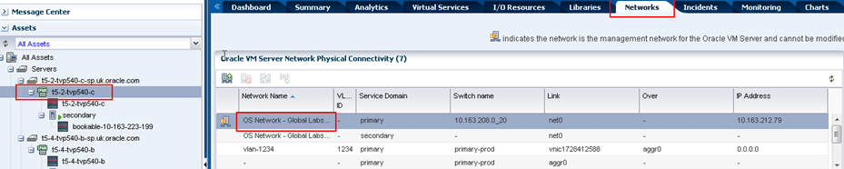
Description of the illustration secondary_vsw.png
-
Configure the aggregation links, as shown in the image below.
-
Ensure the secondary service domain is selected.
-
Select the correct NIC, in this example is
net0. -
Enter a name for the Switch Name, in this example
secondary-mgmt. -
No Network IP address is allocated.
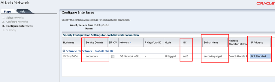
Description of the illustration secondary_vsw_interfaces.png
-
-
Review the summary and click Finish.
You can use the command line to view the newly created virtual switch.
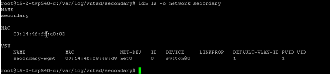
Description of the illustration cli_secondary_vsw_int.png
-
Repeat the steps to create another virtual switch for the aggregated link on the secondary service domain. Ensure that:
-
The secondary service domain is selected.
-
Select the correct NIC, in this example is
aggr0. -
Enter a name for the Switch Name, in this example
secondary-prod. -
No Network IP address is allocated.
-
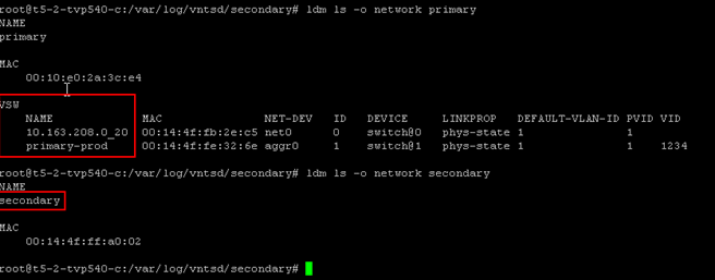
You can verify both virtual switches were created from the command line or UI. In the control domain, it is possible to see the networks crated for the control domain and secondary domain.
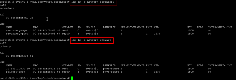
Description of the illustration networkvsw_verify.png
Creating the HA Guest Domain
In Oracle Enterprise Manager Ops Center, it is possible to create two types of Guest Domains: Guest Domain and HA Guest Domain. The required criteria for creating a HA Guest Domain is:
-
Two network connections for each network
-
Redundant storage access to the virtual disks
Since the goal of this paper is to help create a resilient environment, a HA Guest domain is created. The following steps define the procedure:
It is also possible to combine multiple profiles mentioned above in a complex plan, thus enabling just one job to create the Guest HA container and install the OS.
Creating the HA Guest Domain Profile
To create the HA guest domain:
-
Select Plan Management section and expand Profiles and Policies in the Navigation pane.
-
Select Logical Domain profile and click Create Profile in the Actions pane.
-
Enter the following details in the Create Profile - Logical Domain wizard and then click Next.
-
Name and description of the profile.
-
Retain the option to create a deployment plan for this profile.
-
Select HA Guest Domain as the Subtype.
-
-
Provide a name for the HA guest domain and click Next.
-
Enter the configuration details for the HA guest domain and then click Next. In this example, you use Virtual CPU model with 4 CPU threads and 4 GB of memory.
-
Select a library to store the metadata and the HA guest domain's storage, then click Next.
In this example, select the NAS Filesystem Storage as storage type to store the metadata and select the predefined NFS share. Select the Dynamic Block Storage from the menu, which is a Sun ZFS Storage 7120 appliance, to be the storage for the guest domain and specify the size of 20 GB.
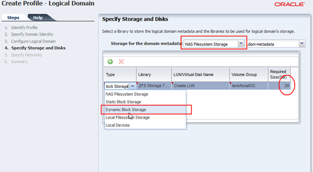
Description of the illustration guest_storage.png
-
Specify the networks to add to the HA Guest by adding two network connections for each of the networks (admin and public).
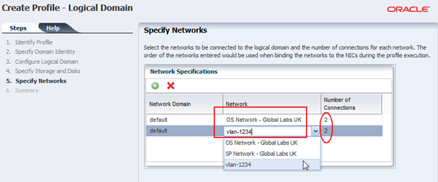
Description of the illustration guest_network.png
-
Review the parameters selected for the profile and click Finish to create the profile.
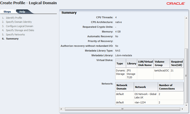
Description of the illustration guest_summary.png
Applying the HA Guest Domain Profile
To apply the logical domain profile in Oracle Enterprise Manager Ops Center:
-
Expand Assets and select the control domain.
-
Click Create Logical Domains in the Actions pane.
-
Select the HA Guest profile that was just created and click Apply Plan.
-
Retain the default name and click Next.
-
Retain the values for metadata and virtual disks, select which devices to multi-path, and chose one for the active path.
Since the objective is to create a redundant guest domain, provide a LUN from both the primary and secondary domains. One path must be chosen as the active path.
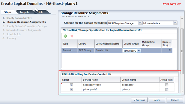
Description of the illustration guest_install_storage.png
Click Next.
-
Choose Untagged as the mode for the public network (vlan network) so that the guest OS will see the network as untagged.
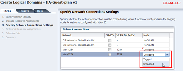
Description of the illustration guest_install_network.png
-
Specify the network from each domain. One connection will be for the control domain and the other for the secondary domain, to ensure that there is redundancy.
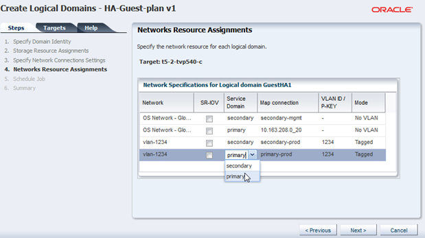
Description of the illustration guest_install_net.png
-
Review the Summary and click Finish to complete the HA guest domain installation.
After the job completes successfully, HA guest domain is created. The guest domain appears in the Navigation pane listed under the corresponding control domain.
Provisioning the HA Guest Domain OS
Installing the OS requires creating the OS Provisioning Profile (OSP) and OS Configuration Profile (OSC), then combining the Profiles in a Deployment Plan to apply it to the HA guest domain.
Creating an OS Provisioning Profile
-
Select Plan Management section and expand Profiles and Policies in the Navigation pane.
-
Select OS Provisioning profile and click Create Profile in the Actions pane.
-
Enter the following details in the Create OS Profile - OS Provisioning wizard and then click Next to specify the OSP parameters.:
-
Name and description of the profile.
-
Select Logical Domain as the Subtype.
-
-
Complete the remaining steps according to your requirements. In the Summary screen click Finish to create the OSP profile.
Creating an OS Configuration Profile
Within this profile you use IPMP for the networks to achieve the goal of having resilient networks.
To create the OSC in Oracle Enterprise Manager Ops Center:
-
Select the Plan Management section in the Navigation pane and expand Profiles and Policies.
-
Select OS Configuration and click Create Profile in the Actions pane.
-
Enter the following details in the Create Profile - OS Configuration wizard:
-
Name and description of the profile.
-
Select logical domain as the Subtype.
Click Next.
-
-
Select to manage the OS automatically and deploy the Agent Controller to manage the asset. Select the option Enable Multiplexed I/O so that you can associate block storage libraries such as FC and iSCSI for storage with the OS.
Click Next to specify the networking details.
-
Select Use IPMP as the networking option, then click Next to specify the networking details.
-
Create two IPMP groups and specify two interfaces for each, then click Next.
Because resilience is required, two IPMP groups are created. One will be used for the admin network and the other from the public network. Each network should have two connections, one from the control domain and another from the secondary service domain.
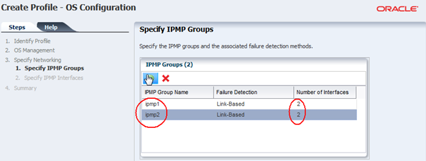
Description of the illustration guest_osc_ipmpgroups.png
-
Specify the physical network interfaces for each IPMP groups as show in the image below, then click Next.
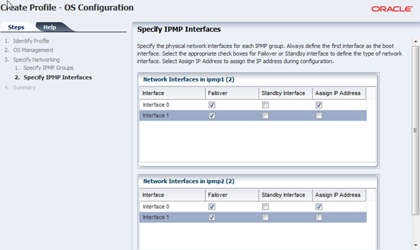
Description of the illustration guest_osc_ipmpint.png
This configuration states how to set up the IPMP groups and how the failover should be initiated, such as Link Based or Probe-Based.
-
Review the summary information, and then click Finish.
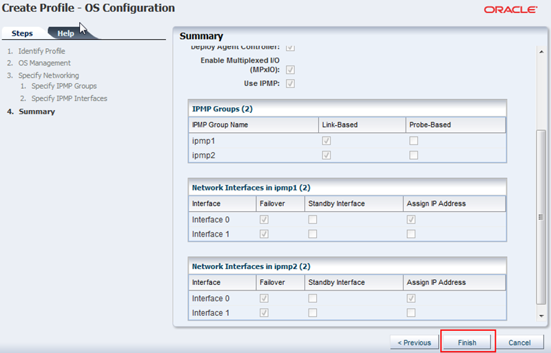
Description of the illustration osc_haguest_summary.png
Creating the Deployment Plan and Provisioning the Control Domain
To create the deployment plan in Oracle Enterprise Manager Ops Center:
-
Select Plan Management section in the Navigation pane.
-
Expand Deployment Plans and select Provision OS.
-
Click Create Deployment Plan in the Actions pane.
The Create a Deployment Plan window is displayed.
-
Enter the following information for the deployment plan:
-
Name and description for the plan.
-
Select Stop at Failure as the Failure Policy.
-
Select the corresponding OSP and OSC profiles created for the HA guest domain.
-
-
Click Save to create the deployment plan.
Once the Deployment plan has been created, the next task is to apply the deployment plan to the HA guest domain.
-
Expand Assets in the Navigation pane and select the HA guest domain.
-
Click Install Server in the Actions pane.
-
Select the recently created Deployment Plan for the HA guest domain, click Apply Plan and complete the first steps of Install Server wizard.
-
In the Boot Interface Resource Assignment step, select the primary interface to install the OS and assign an IP address, then click Next and complete the next steps.
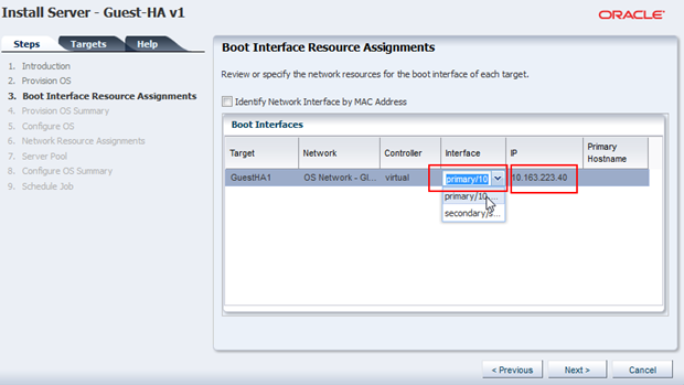
Description of the illustration guest_install_boot.png
-
In the Network Resource Assignments step, select the correct network for each of the IPMP groups, then select the correct Network Interfaces for the IPMP groups, and assign an IP address. Then click Next.
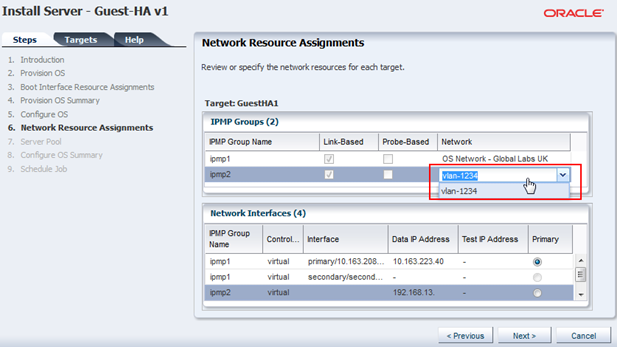
Description of the illustration guest_install_networks.png
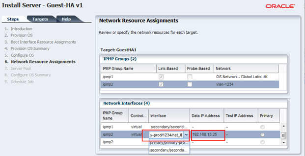
Description of the illustration guest_install_networks2.png
-
Complete the remaining steps, schedule the job to run now, and click Apply to start a job to install the OS on the HA guest domain immediately.
It is possible and recommended to view how the install is progressing. To do this, log on the control domain and view the /var/log/vntsd/ha-guest/console-log file as shown below.
Description of the illustration cli_guesinstall_job.png
Once the job has completed successfully, confirm the setup is correct in the UI or the command line.
What's Next?
This document demonstrated how to improve the resilience of a guest domain by creating a secondary service domain. This was demonstrated by configuring an Oracle SPARC T5-2 server with a control domain and a secondary domain with redundant I/O access to and from a guest domain as configured within Oracle Enterprise Manager Ops Center. This configuration was tested by first halting the control domain and monitoring all guest operations. This test showed no loss of service in the guest domain. The test was repeated by halting the secondary domain, and again, there were no interruptions on the guest.To take resilience to the next step, Server Pools should be introduced. These can perform automatic recovery of guests in the event of server failure. You can refer to the following guide and how tos for information about server pools:
Related Articles and Resources
The Oracle Enterprise Manager Ops Center 12c documentation is located at http://docs.oracle.com/cd/E40871_01/index.htm.
See the following documentation for more detailed information:
-
Oracle Enterprise Manager Ops Center Feature Reference Guide
-
Oracle VM Server for SPARC documentation at
http://www.oracle.com/technetwork/documentation/vm-sparc-194287.html -
Oracle Enterprise Manager Ops Center Administration Guide for information about user roles and permissions
See the Deploy How To library at http://docs.oracle.com/cd/E40871_01/nav/deployhowto.htm.
See the Operate How To library at http://docs.oracle.com/cd/E40871_01/nav/operatehowto.htm.
Documentation Accessibility
For information about Oracle's commitment to accessibility, visit the Oracle Accessibility Program website at http://www.oracle.com/pls/topic/lookup?ctx=acc&id=docacc.
Oracle customers that have purchased support have access to electronic support through My Oracle Support. For information, visit http://www.oracle.com/pls/topic/lookup?ctx=acc&id=info or visit http://www.oracle.com/pls/topic/lookup?ctx=acc&id=trs if you are hearing impaired.
Oracle Enterprise Manager Ops Center Configuring a Secondary Service Domain, 12c Release 2 (12.2.2.0.0)
E57844-01
Copyright © 2007, 2014, Oracle and/or its affiliates. All rights reserved.
This software and related documentation are provided under a license agreement containing restrictions on use and disclosure and are protected by intellectual property laws. Except as expressly permitted in your license agreement or allowed by law, you may not use, copy, reproduce, translate, broadcast, modify, license, transmit, distribute, exhibit, perform, publish, or display any part, in any form, or by any means. Reverse engineering, disassembly, or decompilation of this software, unless required by law for interoperability, is prohibited.
The information contained herein is subject to change without notice and is not warranted to be error-free. If you find any errors, please report them to us in writing.
If this is software or related documentation that is delivered to the U.S. Government or anyone licensing it on behalf of the U.S. Government, then the following notice is applicable:
U.S. GOVERNMENT END USERS: Oracle programs, including any operating system, integrated software, any programs installed on the hardware, and/or documentation, delivered to U.S. Government end users are "commercial computer software" pursuant to the applicable Federal Acquisition Regulation and agency-specific supplemental regulations. As such, use, duplication, disclosure, modification, and adaptation of the programs, including any operating system, integrated software, any programs installed on the hardware, and/or documentation, shall be subject to license terms and license restrictions applicable to the programs. No other rights are granted to the U.S. Government.
This software or hardware is developed for general use in a variety of information management applications. It is not developed or intended for use in any inherently dangerous applications, including applications that may create a risk of personal injury. If you use this software or hardware in dangerous applications, then you shall be responsible to take all appropriate fail-safe, backup, redundancy, and other measures to ensure its safe use. Oracle Corporation and its affiliates disclaim any liability for any damages caused by use of this software or hardware in dangerous applications.
Oracle and Java are registered trademarks of Oracle and/or its affiliates. Other names may be trademarks of their respective owners.
Intel and Intel Xeon are trademarks or registered trademarks of Intel Corporation. All SPARC trademarks are used under license and are trademarks or registered trademarks of SPARC International, Inc. AMD, Opteron, the AMD logo, and the AMD Opteron logo are trademarks or registered trademarks of Advanced Micro Devices. UNIX is a registered trademark of The Open Group.
This software or hardware and documentation may provide access to or information about content, products, and services from third parties. Oracle Corporation and its affiliates are not responsible for and expressly disclaim all warranties of any kind with respect to third-party content, products, and services unless otherwise set forth in an applicable agreement between you and Oracle. Oracle Corporation and its affiliates will not be responsible for any loss, costs, or damages incurred due to your access to or use of third-party content, products, or services, except as set forth in an applicable agreement between you and Oracle.