This tutorial describes how to create ADF task flows that enable navigation, encapsulation, reuse, managed bean lifecycles, and transactions within an application. It includes the basic steps for creating a task flow diagram, adding activities and control flows to it, and running the finished task flow.
In this tutorial, you create two bounded task flows with various components in it. Using a router to determine direction, views to see data, and returns to exit flows, you design the task flows to be able to support search and update functions. You bind the view components with data controls. You define a managed bean to handle a typed password . You define the rules for the router where the password is verified allowing you to login to the application. You create a JSF Page and bind the task flow as a region in the JSF page, creating a parameter value for the username.
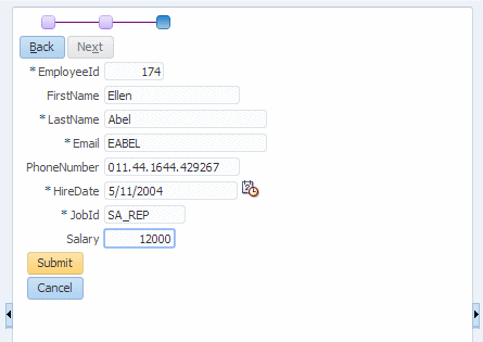
When you work in JDeveloper, you organize your work in projects within an application. JDeveloper provides several templates that you can use to create an Application and projects. The templates are pre configured with a basic set of technologies that are needed for developing various types of applications, and you create your working environment by selecting the template that fits your needs. You can then configure it to add any other technologies you plan to use.
In the first section you are going to create a new Application using the Fusion technology and build reusable business components that will access the database. To create the application and the model components, perform the following steps:
-
In the Applications window, click New Application. Another option is to use the File > New... menu option to create a new application.
-
In the New Gallery, select the General > Applications category, then the ADF Fusion Web Application option. This option creates a data bound ADF web application. The application consists of two projects, one for the data model (ADF-Business Components) and the other for the view controller components (ADF Faces and ADF Task Flows).
Then click OK.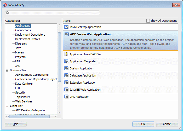
-
In the Create Fusion Web Application dialog box, specify the Application Name to be TaskFlow. Notice that the directory changes to match the new name. You can change the C:\JDeveloper\mywork part of the path to create your files in another location.
In the Application Package Prefix field set the value to be demo. Leave the rest of the values at their default and click Finish.
If you decide to look at some of the additional pages in the wizard, you can notice the Model and ViewController package names have "demo" as their prefix.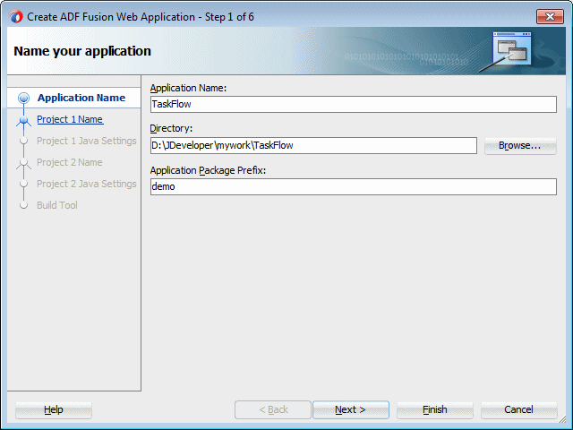
The Overview pane displays a Checklist you can refer to as a guide for developing a Fusion Web Application.
The Checklist is displayed by default when a Fusion Web application is created.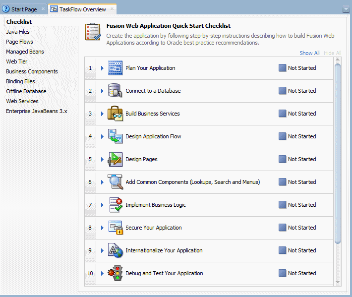
-
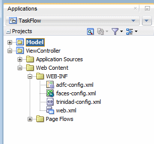
Examine the Applications window and you'll see two new projects now. The default naming rules for these projects are Model for one and ViewController for the other.
-
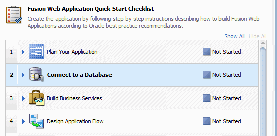
We start creating the model components using the CheckList Overview. Click the Connect to a Database step.
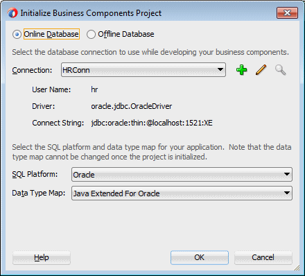
You use the Initialize Business Components Project dialog to select a design time application resource connection to use while working on your business components in this data model project or to create a new application resource connection by copying an existing IDE-level connection.
This dialog appears before you create your first business component, you also use it to globally control the SQL flavor that the view objects will use to formulate SQL statements. Although the default for an Oracle database connection is always the Oracle SQL flavor, other SQL flavors you can choose include OLite (for the Oracle Lite database), SQLServer for a Microsoft SQLServer database, DB2 for an IBM DB2 database, and SQL92 for any other supported SQL92- compliant database. Note that you cannot use the Project Properties dialog to change the SQL flavor after you've initialized a data model project, but you can you can override the SQL flavor in the overview editor for the adf-config.xml file. Specifying the database type in the adf-config.xml file supports generating SQL statements during runtime which can require the actual database type.
-
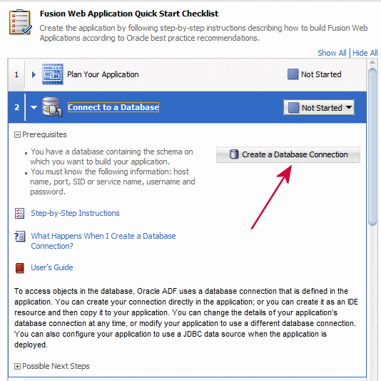
The step expands showing useful information such as prerequisites required for performing this task. Click the Create a Database Connection button.
-
Specify the following properties for the new connection you are creating:
Enter the Oracle JDBC Settings properly to point to the correct host, port and SID for your database. Click the Test Connection button and verify that you got success.
Once done, click the OK button.Property Value Connection Name HRConn Username hr Password hr 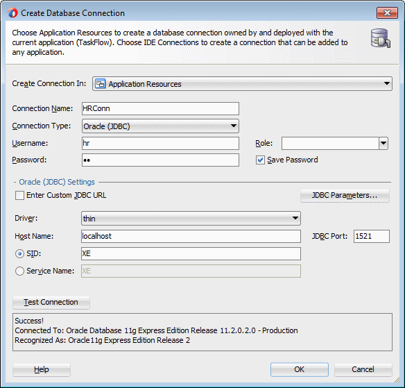
-
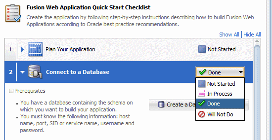
In the Checklist pane, set the status of the Connect to a Database step to Done.
-
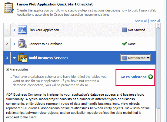
Collapse the database node and click the Build Business Services step to expand it. Then click the Go to Sub steps button.
-
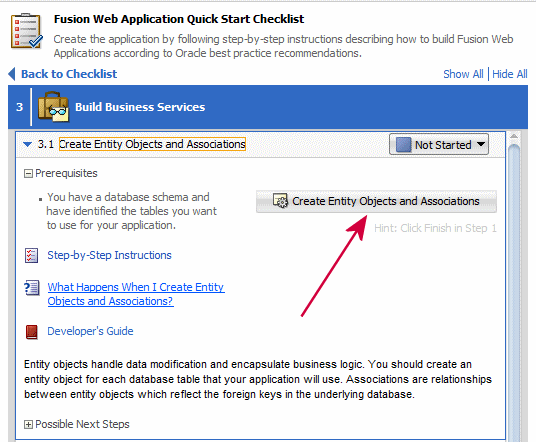
In the sub task list, click the Create Entity Objects and Associations sub task.
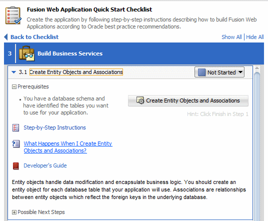
Then click the Create Entity Objects and Associations button.
An entity object is the ADF Business Components component that represents a row in the specified data source and controls modifying its associated attributes.
Importantly, it allows you to encapsulate domain business logic to ensure that your business policies and rules are consistently validated. Entity objects support numerous declarative business logic features to enforce the validity of your data. You will typically complement declarative validation with additional custom application logic and business rules to cleanly encapsulate a maximum amount of domain business logic into each entity object. Your associated set of entity objects forms a reusable business domain layer that you can exploit in multiple applications. In most cases, an entity is mapped to one database table.
-
In the Select Project for Action dialog, select the Model project.
Click OK.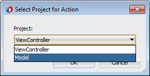
-
In the Initialize Business Components Project dialog the HRConn connection should be selected. Then click OK.
-
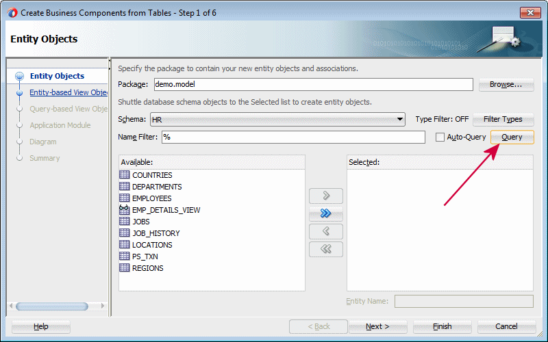
In the Entity Objects page of the Create Business Components from Tables wizard, click the Query button to examine the data dictionary and see available tables.
-
Select the EMPLOYEES table in the Available list, and click the right arrow
 to move your selections to the Selected list. This step creates updatable Entity Objects based on the tables you select.
Then click Next to continue.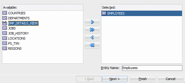
-
In the Entity-based View Objects dialog, move Employees (HR.EMPLOYEES) to the Selected list. This step creates matching view objects to perform queries on the entity object you created before.
Notice how the name changes to EmployesView(Employees). You see the VO name and the reference EO it was created from.
Then click Next to continue.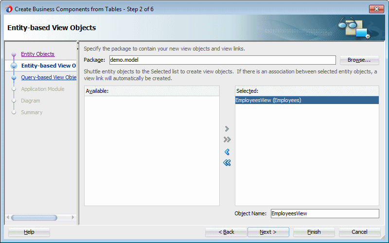
-
In the Query-based View Objects dialog, Click Next to continue.
A view object is an Oracle Application Development Framework (Oracle ADF) component that encapsulates a SQL query and simplifies working with its result.
There are several types of view objects that you can create in your ADF Business Components project:
- Read-only view objects when updates to data are not necessary (can also be entity-based)
- Entity-based view objects when data updates will be performed
- Static data view objects for data defined by the view object itself
- Programmatically populated view object.
An entity-based view object can be configured to support updatable rows when you create view objects that map their attributes to the attributes of one or more existing entity objects. The mapped entity object is saved as an entity usage in the view object definition. In this way, entity-based view objects cooperate automatically with entity objects to enable a fully updateable data model. The entity-based view object queries just the data needed for the client-facing task and relies on its mapped entity objects to automatically validate and save changes made to its view rows. Like the read-only view object, an entity-based view object encapsulates a SQL query, it can be linked into master-detail hierarchies, and it can be used in the data model of your application modules.
-
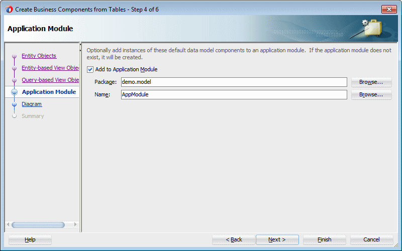
In the Application Module dialog, click Finish to create the business components in the Model project.
An application module is an ADF Business Components component that encapsulates the business service methods and UI-aware data model for a logical unit of work related to an end-user task.
The application module is the "work unit" container that includes instances of the reusable view objects required for the use case in question, related through metadata to the underlying entity objects in your reusable business domain layer whose information the use case is presenting or modifying.
-
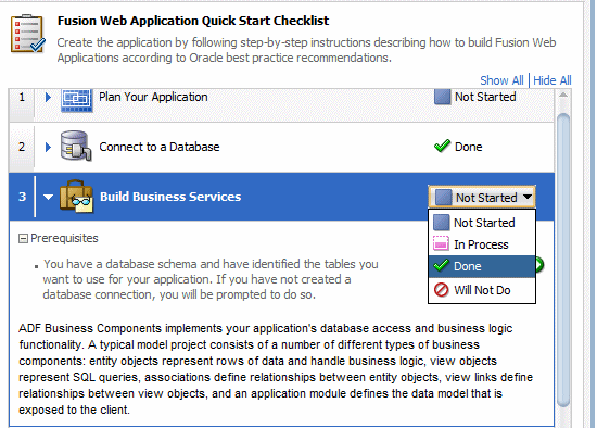
In the Checklist, set the status of the Create Entity Objects and Associations step to Done. Then click the Close Step 3 button.
Note: Since steps 3.2, 3.3 and 3.4 have also been completed, we could as well set their status to done, but we'll do it at a higher level.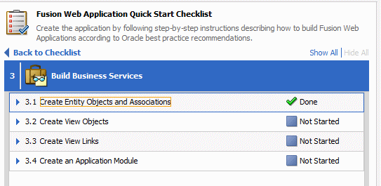
-
Set the status of the Build Business Services step to Done.
-
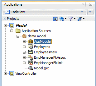
The work on the model project is performed. Expanding the Model project, the Applications window should look like the following:
-
Click the Save All
 icon on the JDeveloper menu bar, or select File | Save All from the menu.
 Next we'll work on the ViewController project.
With the TaskFlow application loaded in JDeveloper, you create a bounded task flow diagram including views, and returns. To do this, perform the following steps:
-
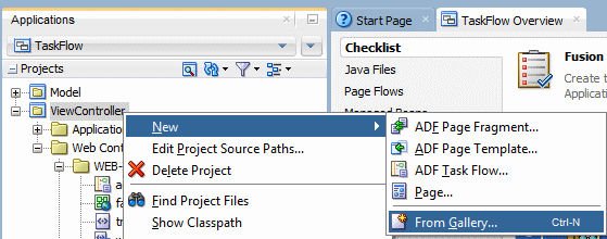
In the Applications window, right click the ViewController node and select New > From Gallery from context menu.
An ADF bounded task flow is used to encapsulate a reusable portion of an application.
A bounded task flow is similar to a Java method in that it:
- Has a single entry point
- May accept input parameters
- May generate return values
- Has its own collection of activities and control flow rules
- Has its own memory scope and managed bean life span (a page flow scope instance)
An ADF bounded task flow consists of its own set of private control flow rules, activities, and managed beans. A caller requires no internal knowledge of such things as page names, method calls, child bounded task flows, managed beans, and control flow rules within the bounded task flow boundary. Input parameters can be passed into the bounded task flow, and output parameters can be passed out on exit of the bounded task flow. Data controls can be shared between task flows.
-
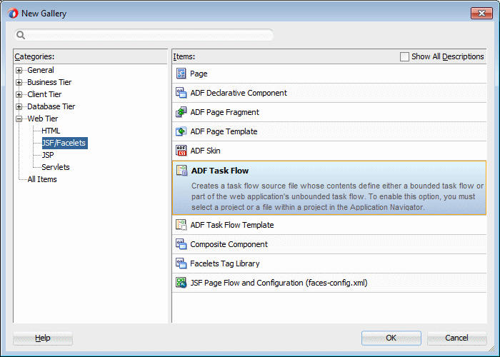
In the New Gallery, expand the Web Tier > JSF/Facelets node and select ADF Task Flow.
-
In the Create Task Flow dialog, enter emp-update-flow as the File Name. Select the following checkboxes.
Then click OK.Property Value Create as Bounded Task Flow Checked Create with Page Fragments Checked Create Train Checked 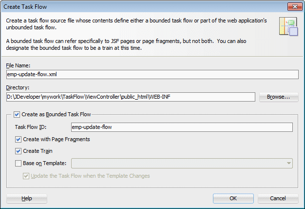
-
A new empty task flow diagram displays and a new entry is created in the Applications window.
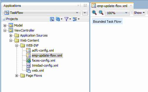
-
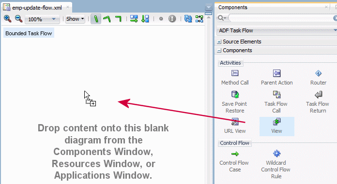
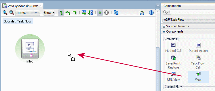
Select the View component
 from the Components window and drag and drop it onto the diagram surface.
The primary type of task flow activity is a view, which displays a JSF page or page fragment.
A page fragment is a JSF JSP document that is rendered as content in another JSF page. Page fragments are typically used in bounded task flows. The bounded task flow can be added to a page as a region. This allows for reuse of the task flows, and allows a page to include multiple areas, each containing specific flow.
A view activity is associated in metadata with a physical JSF page or page fragment. The view activity is identified by an id attribute. The page or page fragment name is identified by a <page> element in the task flow metadata. The view activity ID and page name do not have to be the same.
-
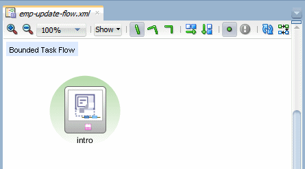
Change the default name to intro.
-
Create a new view
 on the diagram next to the intro one.
Rename it search.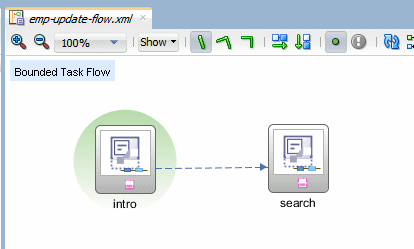
-
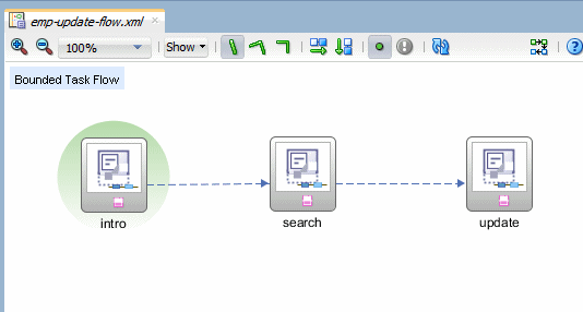
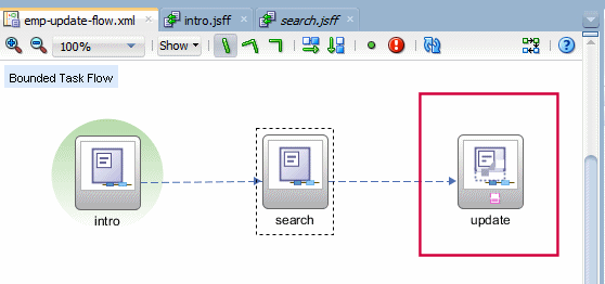
Create a third view
 on the diagram.
Rename it update. Your diagram should look similar to the image below.
Notice the dotted line between each of the three view. Since we created the task flow with trains, there's an implicit flow between all the views.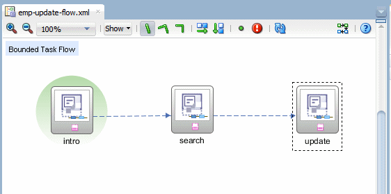
-
Save all your work.
Instead of representing an application as a single large JSF page flow, you can break it up into a collection of reusable task flows. Each task flow contains a portion of the application's navigational graph. The nodes in the task flows are activities. An activity node represents a simple logical operation such as displaying a page, executing application logic, or calling another task flow. The transactions between the activities are called control flow cases.
The two types of ADF task flow are:
- Unbounded task flow: A set of activities, control flow rules, and managed beans that interact to allow a user to complete a task. An ADF unbounded task flow consists of all activities and control flows in an application that are not included within any bounded task flow.
- Bounded task flow: A specialized form of task flow that, in contrast to an unbounded task flow, has a single entry point and zero or more exit points. It contains its own set of private control flow rules, activities, and managed beans. An ADF bounded task flow allows reuse, parameters, transaction management, and reentry.
The intro page is the entry point of this task flow and you'll see how to create a train within the pages. To do this, perform the following steps:
-
On the emp-update-flow diagram, double click the intro view component to create the page.
In the Create New ADF Page Fragment dialog, click OK to accept default values.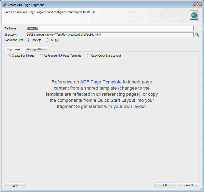
-
The page design pane opens up. From the Components window, in the ADF Faces General Controls > Location group, select the Train component
 and drop it onto the page design surface.
A train represents a progression of related activities that guides an end user to the completion of a task.
The end user clicks a series of train stops, each stop linking to a particular page.
An optional Train Button Bar component can be added which contains buttons that provide an additional means to navigate backwards and forwards though the stops. This component can be used in conjunction with the train component to provide multiple ways to navigate through train stops..
Each bounded task flow can have a single train only. If the bounded task flow logically includes multiple trains, you must add each train to a separate bounded task flow.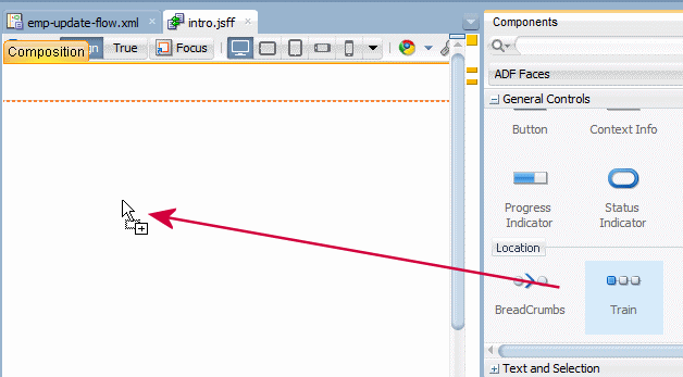
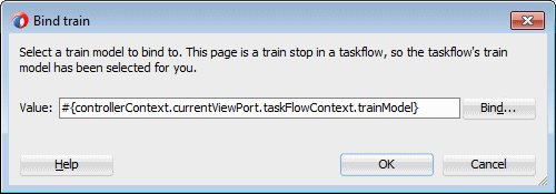
In the Bind Train dialog, click OK to accept the default value.
-
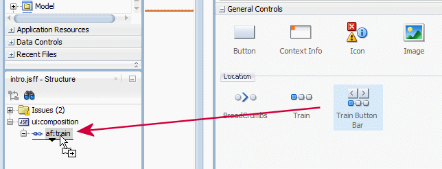
Select the Train Button Bar component
 and drop it underneath the Train component in the Structure window.
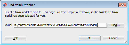
In the Bind trainButtonBar dialog, click OK to accept the default value.
-
From the Components window, in the ADF Faces Text and Selection group, select the Output Text component
 and drop it underneath the Train Button Bar.
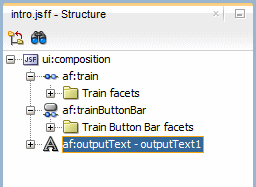
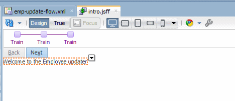
Open the Properties window if not already there (View > Properties window or use the key combination [Ctrl] + [Shift] + [I]), and enter Welcome to the Employee updater in the value field.
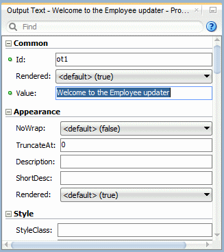
The page should look like this:
-
Save all your work and then click the emp-update-flow tab to reopen the task flow diagram.

-
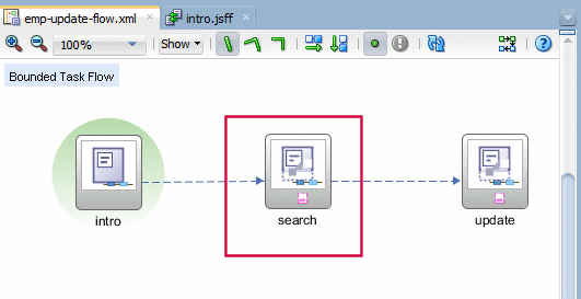
Double click the search view component to create the search page.
-
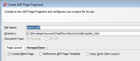
In the Create New ADF Page Fragment dialog, click OK to accept default values.
-
The page design pane opens up. From the Components window, in the ADF Faces General Controls group, select the Train component
 and drop it onto the page design surface.
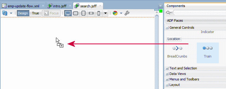
In the Bind Train dialog, click OK to accept the default value.

-
Select the Train Button Bar component
 and drop it underneath the Train component.
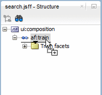
In the Bind trainButtonBar dialog, click OK to accept the default value.

-
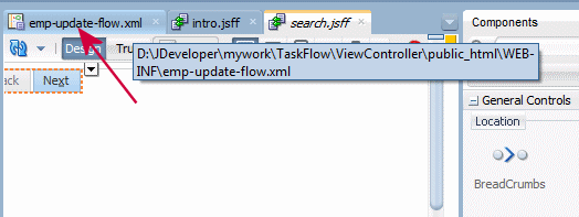
Save all your work, and then click the emp-update-flow tab to reopen the task flow diagram.
-
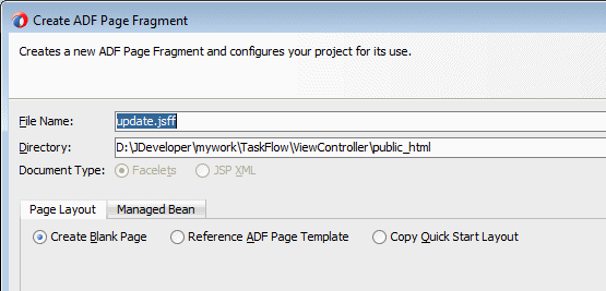
Double click the update view component to create the update page.
-
In the Create New JSF Page Fragment dialog, click OK to accept default values.
-
The page design pane opens up. From the Components window, in the ADF Faces General Controls group, select the Train component
 and drop it onto the page design surface.
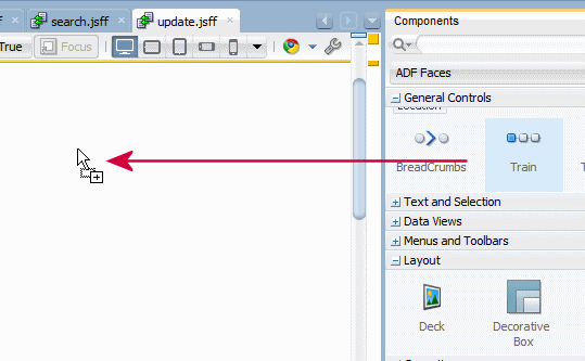
In the Bind Train dialog, click OK to accept the default value.

-
Select the Train Button Bar component
 and drop it underneath the Train component.
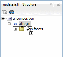
In the Bind trainButtonBar dialog, click OK to accept the default value.

-
Click the Save All icon to save the application.
The search and update pages need to bind data control components. The search page for querying employees on any column criteria and the update page for displaying and updating an employee's salary. To do so, perform the following steps:
-
Click the search tab to reopen the page.
-
In the Applications Navigator open the Data Controls accordion and expand the following nodes AppModuleDataControl > EmployeesView1 > Named Criteria and drag and drop the All Queriable Attributes on the page.
A data control is essentially a bridge that makes data from a source, available to the user interface, in an ADF Fusion Web Application.
By default, for all business components, a data control is created to query all of the attributes in the view object.When dropped on a page this data control produces a page where data can be displayed as an output component.
You can use the objects in the data control to create data bound user interface components. A few of the most commonly used types of data controls include the following:
ADF Business Components : This type of data control is generated by JDeveloper when you create an application module in your ADF Business Components application.
JavaBean : This type of data control obtains the structure of the data from POJOs (plain, old Java objects).
EJB : The EJB data control is essentially the same as the JavaBean data control, except that it uses features inherent in the EJB architecture to obtain the structure of the data.
Web Service : A Web Service data control obtains the structure of the data from the WSDL for a web service.
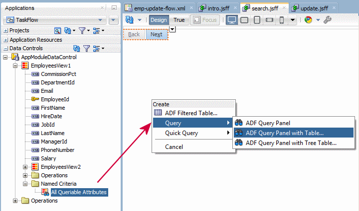
From the pop up menu, select Create > Quick Query > ADF Quick Query with Table option.
A quick query search form is intended to be used in situations where a single search will suffice or as a starting point to evolve into a full query search.
Both the query and quick query search forms are ADF Faces components. A quick query search form has one search criteria field with a drop down list of the available searchable attributes from the associated data collection. Typically, the searchable attributes are all the attributes in the associated view object.
You can exclude attributes by setting the attribute's Display Hint property in the Control Hints page of the Edit Attribute dialog to Hide. The user can search against the selected attribute or search against all the displayed attributes. The search criteria field type will automatically match the type of its corresponding attribute. An Advanced link built into the form offers you the option to create a managed bean to control switching from quick query to advanced mode query search form.

-
In the Edit Table Columns dialog, select the Single Row Selection and Enable Sorting options.
Then click OK.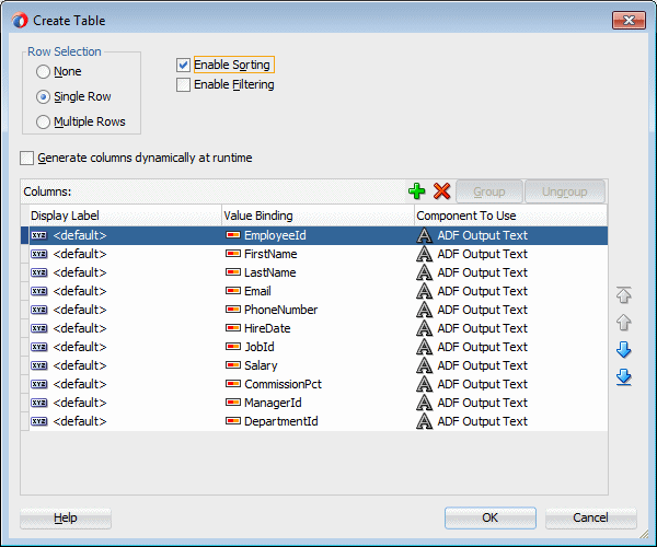
-
The page should look like the following:
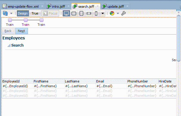
-
Save your work and then click the update tab to open the page.
-
From the Data Controls panel, select AppModuleDataControl > EmployeesView1 then drag and drop it onto the update page.
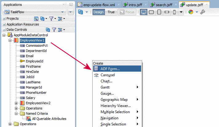
-
From the pop up menu select Create > ADF Form option.
Dropping an object as a form from the Data Controls panel has the same effect as dropping a single attribute, except.
...multiple attribute bindings and associated UI components are created. The attributes on the UI components (such as value) are bound to properties on that attribute's binding object (such as inputValue) or to the values of control hints set on the corresponding business object.
When you drag an attribute or an object onto a JSF page and drop it as a UI component, among other things, a page definition file is created for the page (if one does not already exist). Bindings for the iterator and attributes are created and added to the page definition file. Additionally, the necessary JSPX page code for the UI component is added to the JSF page..
-
In the Create Form dialog, in the Fields list, select the last 3 rows (CommissionPct, ManagerID and DepartmentId) and click the Delete button
 to discard the fields. Then select the Include Submit Button option and click OK.
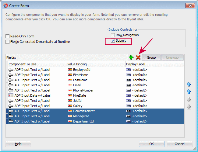
-
In the Components window, select the Button icon
 and drag and drop it next to the Submit button.
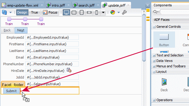
-
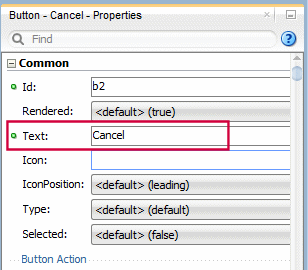
In the Properties window, type Cancel in the Text field for the button.
-
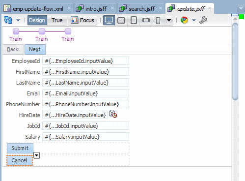
The page should look like the following:
-
Click the Save All
 icon to save the application.
To end a transaction, you can either use a return activity or you can use a button bound to an operation action. If possible, use a task flow return activity. Using a task flow return activity will commit all the data used in views on the ADF task flow. It also makes it easier to see where your application is doing commits and rollbacks, and is therefore easier to maintain. To implement return activities for transaction controls, perform the following steps:
-
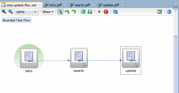
Click the emp-update-flow tab to reopen the task flow diagram.
-
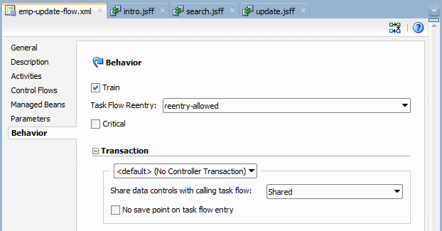
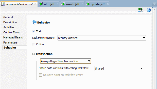
Click the Overview tab and then select the Behavior tab.
-
In the Transaction group, set the following properties from the list: Always Begin New Transaction.
A transaction is a persisted collection of work that can be committed or rolled back together as a group.
You can use a bounded task flow to represent a transaction and to declaratively manage transaction boundaries. For example a customer registration and a employee registration task flow might be implemented with the use of task flow return activities. A Cancel button would implement a rollback in the task flows. A Save button would then be used for commit functionality.
This way, each individual employee update is seen as a single row granularity transaction.
-
Back in the diagram, select the Task Flow Return component
 and drop it underneath the update view.
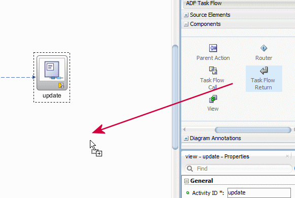
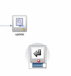
Rename it commit.
 r
r -
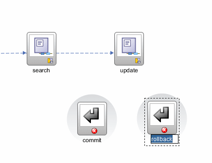
Select again the Task Flow Return component
 and drop it underneath the update view. Rename it rollback.
-
Select the Control Flow Case component
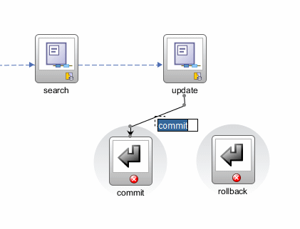
 from the Components window and click inside the update view then click inside the commit return.
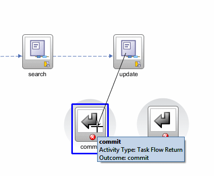
Rename it commit.
-
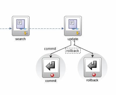
Select the Control Flow Case component
 from the Components window and click inside the update then click inside the rollback return. Then rename it rollback.
-
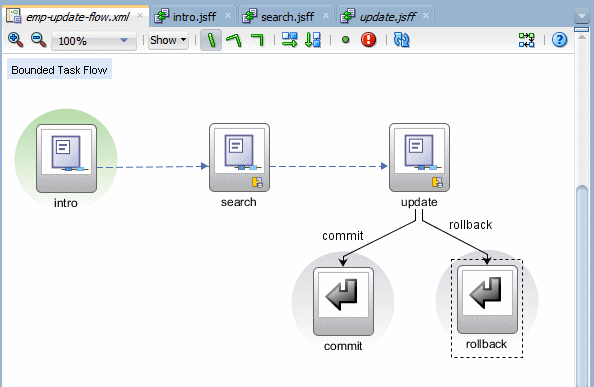
The task flow diagram should look like the following:
-
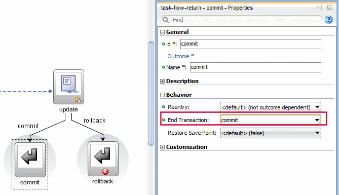
Select the commit return component and in the Properties window, in the Behavior tab, for the End Transaction field, select commit, from the list of values.
-
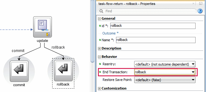
Repeat the same operation selecting the rollback return and select rollback from the list for the End Transaction field.
-
Click the Save All
 icon to save the application.
 -
Click the update tab to open the update page design, and select the Submit button.
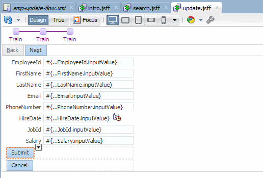
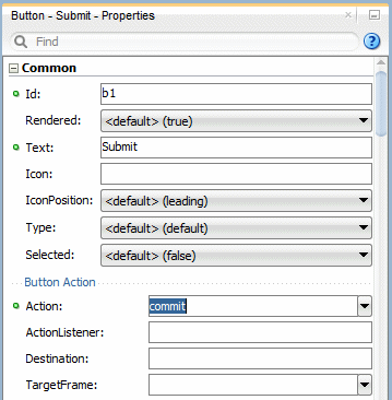
In the Properties window, in the Action field, select commit from the list.
-
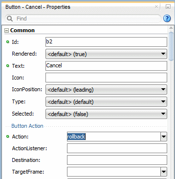
Select the Cancel button and in the Properties window, in the Action field, select rollback from the list.
-
Click the Save All
 icon to save the application.
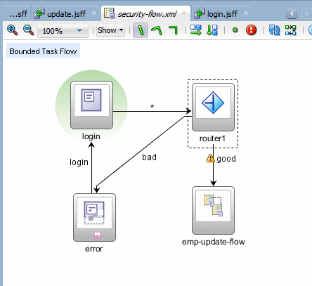
We want to restrict the access to the application through a login process. We create a login page, a router, an error page and the previously created task flow. To create this task flow, perform the following steps:
For example, JDeveloper, by default, creates an empty unbounded task flow (source file name is adfc-config.xml) when you create a Fusion web application using the Fusion Web Application template. At runtime, the Fusion web application can call bounded task flows from activities that you added to this unbounded task flow.
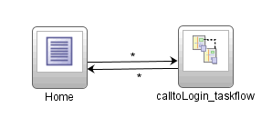
As shown below, the first activity to execute in an application is often a view activity within an ADF unbounded task flow. A view activity represents a JSF page that displays as part of the application. The activity starts with the Home view activity and then calls a bounded task flow. The calltoLogin_taskFlow activity calls a bounded task flow that enables a user to log into the application.
You can also design an application in which all application activities reside within the ADF unbounded flow. This mimics a Struts or JSF application, but doesn't take advantage of ADF bounded task flow functionality. To take full advantage of task flow functionality, use ADF bounded task flows.
-
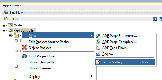
In the Applications window, right click the ViewController node and select New > From Gallery from the context menu.
-
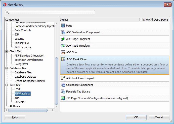
In the New Gallery, click the Web Tier > JSF / Facelets node and select ADF Task Flow. Then click OK.
-
In the Create Task Flow dialog, enter security-flow as the File Name. Select the the Create as Bounded Task Flow and Create with Page Fragments checkboxes.
Click OK.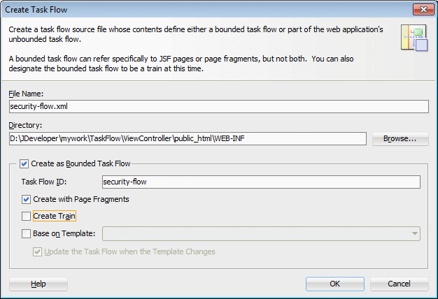
-
A new empty task flow diagram displays and a new entry is created in the Applications window.
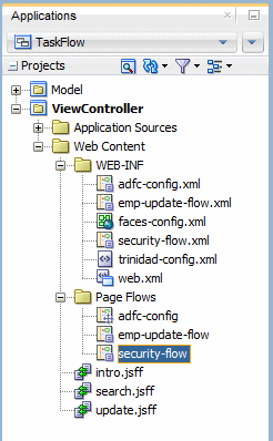
-
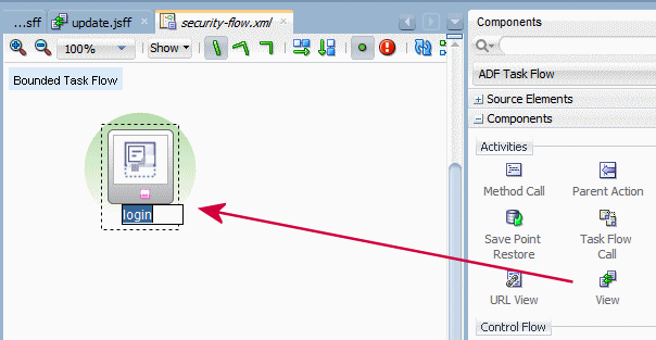
Select the View component
 from the Components window and drag and drop it onto the diagram surface and rename the view to login.
-
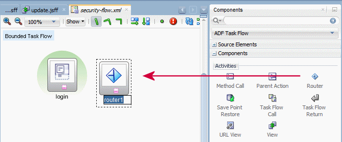
Select the Router component
 and drop it next to the login view.
You can use a router activity to declaratively route control to activities based on logic specified in an EL expression.
Each control flow can correspond to a different router case. Each router case contains the following elements, which are used to choose the activity to which control is next routed. The first expression that evaluates to true is used to determine the corresponding outcome.
expression: An EL expression evaluating to either true or false, for example, #{(pageFlowScope.welcomeUserRegistrationBean.userSelection eq 'Customer')}
outcome: A value returned by the router activity if the EL expression evaluates to true, for example, newCustomer. If the router outcome matches a from-outcome on a control flow case, control passes to the activity that the control flow case points to.
If none of the cases for the router activity evaluates to true, or if no cases are specified, the outcome specified in the router default outcome field (if any) is used.
-
From the Applications window, select the emp-update-flow and then drag and drop it on the diagram below the router.
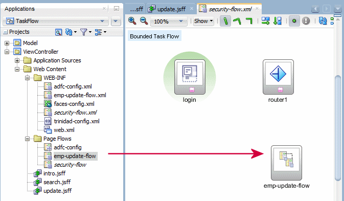
-
Select the View icon
 from the Components window then drag and drop it on the diagram surface and name it error.
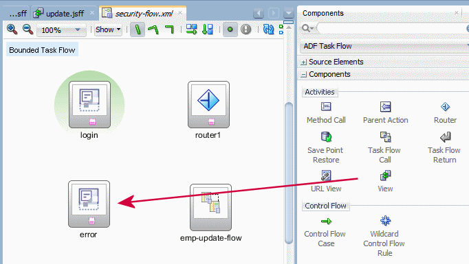
-
Select the Control Flow Case icon
 and click inside the login view, then click inside the router.
 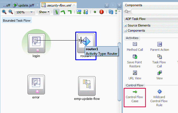 r
r -
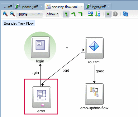
Repeat the previous operation to draw a Control Flow Case
 from the router to the error view.
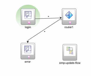
Rename the flow to bad.
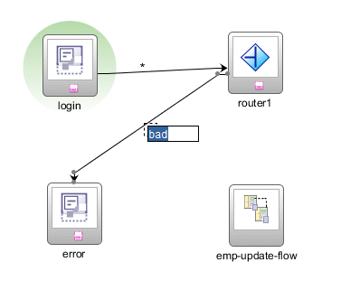
-
Repeat the previous operation to draw a Control Flow Case
 from the router to the emp-update-flow view.
Rename it to good.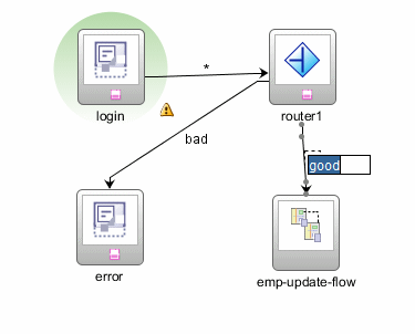
-
Repeat the previous operation to draw a Control Flow Case
 from the error view to the login view.
Rename the flow login. Your diagram should look like the following: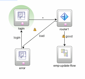
-
The second task flow is complete. Click the Save All
 icon to save the application.
We create a login page with a password field, then we create a backing bean for the password value. Then the router, depending on the password value, leads to an error page or to the emp-update flow. To create the pages and implement the router rules, perform the following steps:
-
In the diagram, double click the login view icon to create the page. In the Create New ADF Page Fragment, click OK to accept default values.
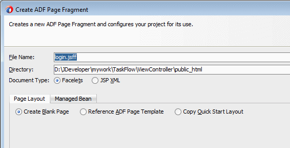
-
In the Components window, drag and drop an Input Text icon onto the login page.
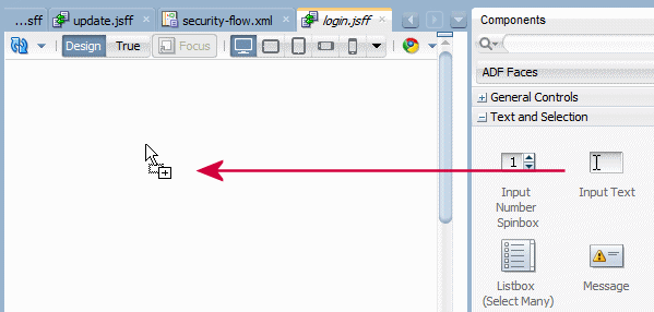
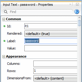
Enter password as the label.
-
In the Advanced tab, next to the Binding field, select Edit from the drop down list.
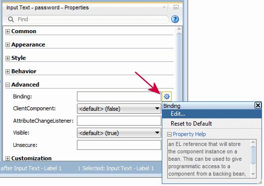
In the Edit Property dialog, click the New button to create a Managed Bean to hold the password value. If we already had a bean to perform this functionality, we could just select it, and then select an existing method or create a new one.
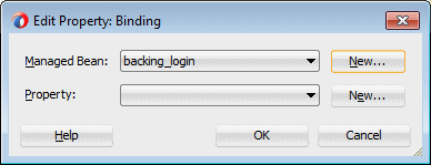
Managed beans are Java classes that you register with the application using various configuration files.
When the JSF application starts up, it parses these configuration files, and the beans listed within them are made available. The managed beans can be referenced in an EL expression, allowing access to the beans' properties and methods. Whenever a managed bean is referenced for the first time and it does not already exist, the Managed Bean Creation Facility instantiates the bean by calling the default constructor method on it. If any properties are also declared, they are populated with the declared default values.
Use managed beans to store logic that is related to the UI rendering only. All application data and processing should be handled by logic in the business layer of the application. Similar to how you store data-related logic in the database using PL/SQL rather than a Java class, the rule of thumb in a Fusion web application is to store business-related logic in the middle tier. This way, you can expose this logic as business service methods, which can then become accessible to the ADF Model layer and be available for data binding.
In the Create Managed Bean dialog, enter the following values:
Property Value Bean Name backing_login Class Name backing_login Package backing Extends java.lang.Object Scope request Generate Class If It Does Not Exist (checked) 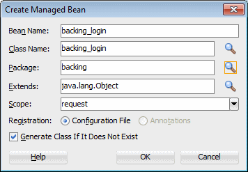
Click OK.
-
Back in the Edit Property, click the New button next to the Property field.
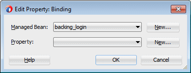
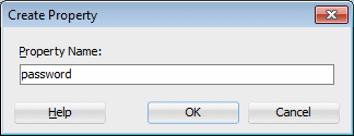
In the Create Property dialog, enter password as the Property Name. Click OK to create the property and OK again the complete the binding.
-
The Advanced node, in the Properties window, for the input text component should look like the following:
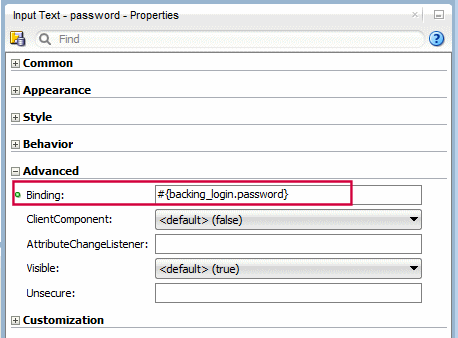
Notice that for a realistic password field, you would also set the Advanced > Visible property to false to hide the typed password value. -
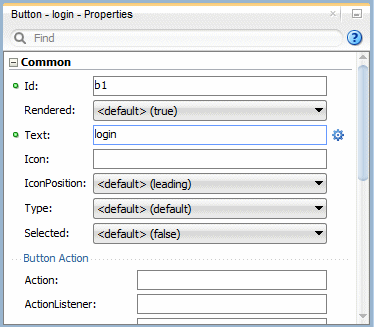
Drag and drop a Button component
 underneath the password field.
Change the Text property to login.
-
Back on the security-flow, select the router.

-
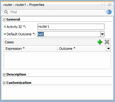
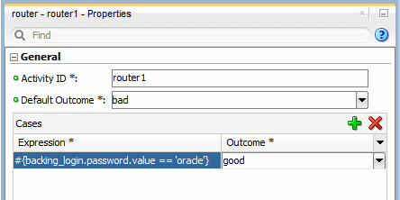
In the Properties window for the router, select bad from the drop down list as the default outcome.
-
Add an outcome case by clicking the Add button
 in the Cases panel.
 -
In the Expression field select the Expression Builder option from the list.
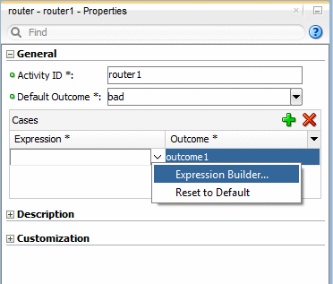
Expand the following nodes ADF Managed Beans > backing_login > password and select the value variable, then select the '==' operand and type 'oracle'.
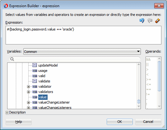
Click OK.
In this example we have coded oracle as a hard coded value for the password.
-
Back in the Properties window, select good as the outcome, so that if the password entered is equal to oracle, the flow takes you through the 'good' flow to the emp-update flow, otherwise to the error page.
-
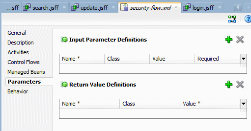
Now we need to create a parameter to work the managed property value. In the security-flow diagram, click the Overview tab and then the Parameters tab.
A called ADF bounded task flow can accept input parameters and can pass return values to the caller upon exit.
To pass an input parameter to a bounded task flow, you must specify one or more:
- Input parameters on the task flow call activity. These specify where the calling task flow will store parameter values.
- Input parameter definitions on the called bounded task flow. These specify where the called bounded task flow can retrieve parameter values..
The input parameter name specified for each option will be the same in order to map input parameter values back into the called bounded task flow. The value for each corresponds to the mapping between where the value will be retrieved within the caller and the called task flow. If you don't specify a value for the input parameter, the value defaults to #{pageFlowScope.parmname}, where parmname is the name of your parameter.
You can specify on the input parameter definition for the called bounded task flow whether an input parameter is required. If a required input parameter is not received, an error occurs (these are flagged at design time as well as at runtime). An input parameter definition that is identified as not required can be ignored during task flow call activity creation. By default, all objects are passed by reference. Task flow call activity input parameters can be passed by reference only if managed bean objects are passed, not individual values. By default, primitive types (for example, int, long, or boolean) are passed by value.
-
In the Input Parameter Definitions, click the Add button
 .
. 
-
Set the parameter to the values from the table below, then save all your work.
Property Value Name username Class java.lang.String Value (auto populated) Required true 
-
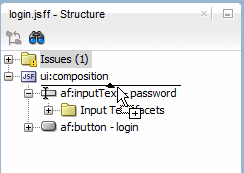
Click the login.jsff tab to open the page,and drag and drop an Output Text component above the password input text.
-
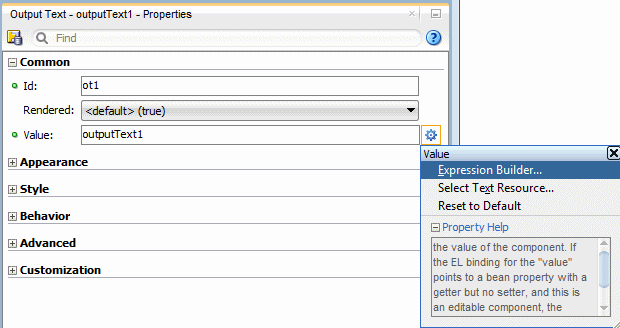
In the Properties window, select the Expression Builder... option from the Value field list.
In JSF, you use a simple expression language (called EL) to bind to the information you want to present and/or modify.
Example expressions look like #{userInfoBean.principalName} to reference a particular user's name, or #{userInfoBean.principalName eq 'SKING'} to evaluate whether a user's name is SKING or not. At runtime, a generic expression evaluator returns the String and boolean value of these respective expressions, automating access to the individual objects and their properties without requiring code.
At runtime, the value of certain JSF UI components is determined by the value attribute. While a component can have static text as its value, typically the value attribute will contain a binding that is an EL expression that the runtime infrastructure evaluates to determine what data to display. For example, an outputText component that displays the name of the currently logged-in user might have its value attribute set to the expression #{userInfoBean.principalName}. Since any attribute of a component can be assigned a value using an EL expression, it's easy to build dynamic, data-driven user interfaces. For example, you could hide a component when a user is not logged in by using a boolean-valued expression like #{userInfoBean.prinicpalName !=null} in the UI component's rendered attribute. If there is no principal name in the current instantiation of the userInfoBean, the rendered attribute evaluates to false and the component disappears from the page.
-
In the Expression Builder make sure to clear out the expression field,select All for the Variables, then expand ADF Managed Beans > pageFlowScope and select username.
Then click OK.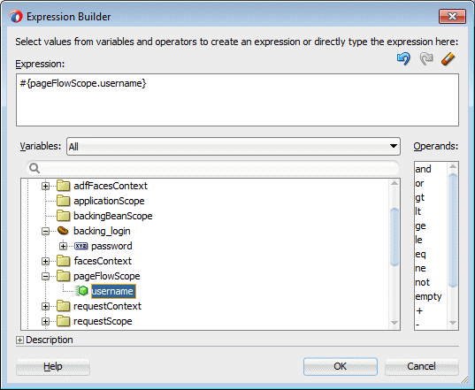
-
Click the security-flow tab to open the task flow diagram and double click the error view to create the page.
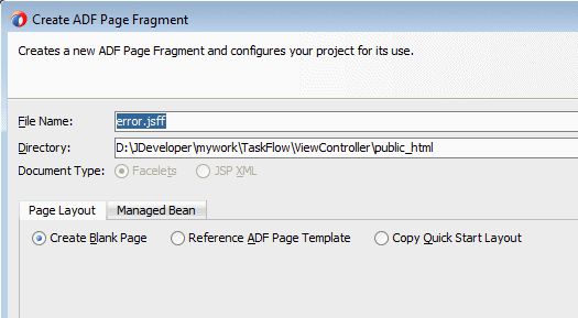
In the Create New ADF Page Fragment dialog, click OK to accept default values.
-
From the Components window, drag and drop an Output Text
 onto the page.
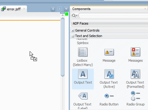
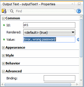
In the Properties window, enter Error, wrong password in the Value field.
-
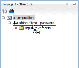
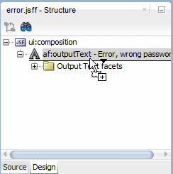
In the Design editor, press Enter to add a new row and drag and drop a Button component
 underneath the error text. You can also use the Structure window as shown below.
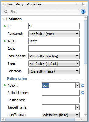
In the Properties window, change the Text field to Retry, and from the list, select login as the action.
-
Click the Save All
 icon to save the application.
To create JSF Page that uses the task flow, perform the following steps:
-
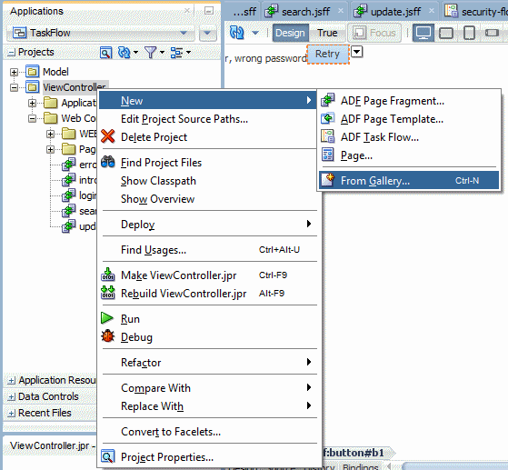
Right click the ViewController node in the Applications window and select New > From Gallery from the context menu.
-
In the New Gallery, select Web Tier as the Category and JSF/Facelets and Page as the Item.
Then click OK.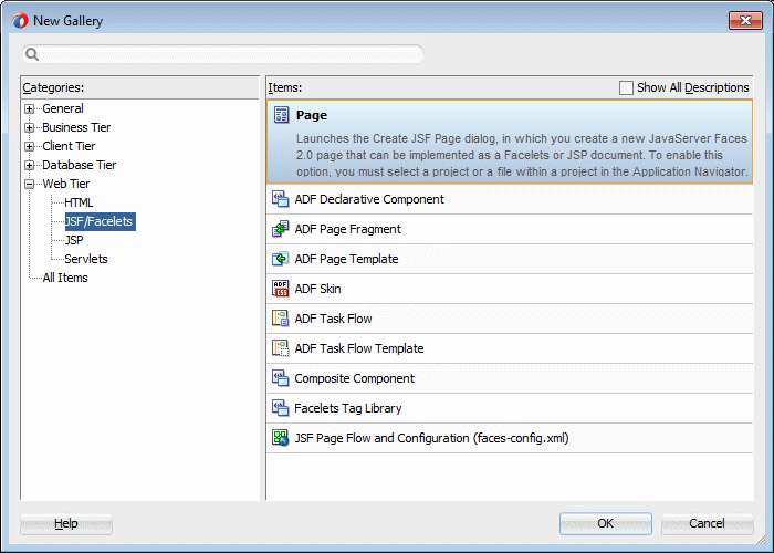
-
In the Create JSF Page dialog, enter master as the File Name and checking the Reference ADF Page Template option, select the Oracle Three Column Layout.
Then click OK.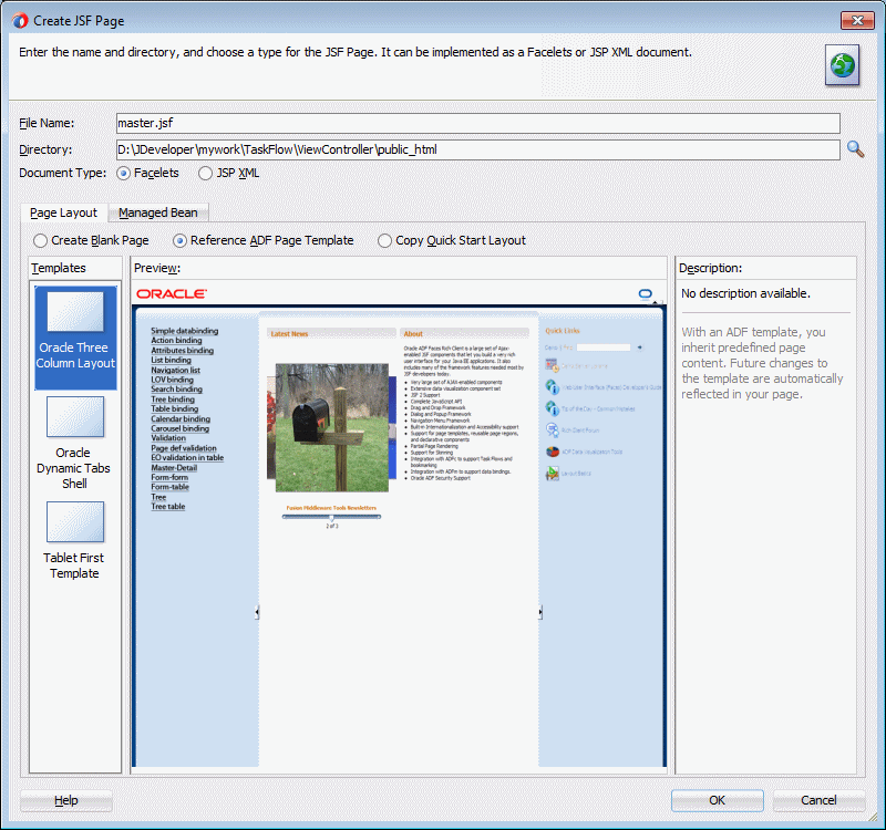
-
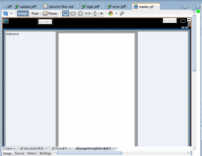
Scroll around to see the displayed page in the editor.
-
From the Components window, drag and drop an Output Text component
 onto the start facet.
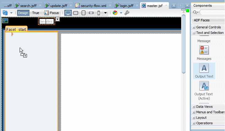
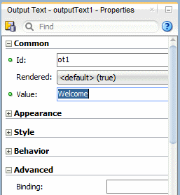
Change the Value field to Welcome in the Properties window.
-
In the ViewController > Web Content > WEB-INF node, drag and drop security-flow.xml onto the Facet center.
Select Region from the menu.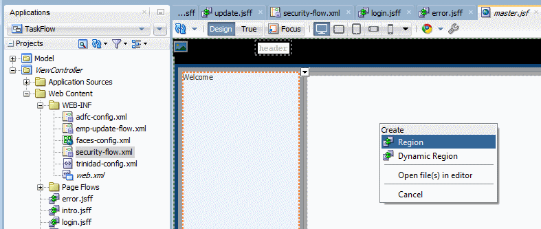
You can render a bounded task flow in a JSF page or page fragment (.jsff) by using an ADF region.
An ADF region comprises the following:
- An af:region tag that appears in the page or page fragment where you render the region
- An instance object that implements RegionModel from the following package: oracle.adf.view.rich.model
- A task flow binding (task Flow) in the page definition that identifies the bounded task flow to use in the ADF region
.
When first rendered, the ADF region's content is that of the first view activity in the bounded task flow. The view activities used in the bounded task flow must be associated with page fragments, not pages. You can pass values to the ADF Region using task flow binding input parameters or contextual events. In addition, you can configure the task flow binding's parametersMap property to determine what input parameters the task flow binding passes from the bounded task flow to the ADF region.
ADF regions can be configured so that you determine when the region activates or refreshes. You can also configure an ADF region and a bounded task flow so that navigation control stops in the bounded task flow and passes to the page that contains the ADF region. Finally, you can create dynamic regions (ADF dynamic regions) where the task flow binding determines at runtime what bounded task flow renders in the region and configure a dynamic region link so that end users can change the bounded task flow that renders in the ADF dynamic region at runtime..
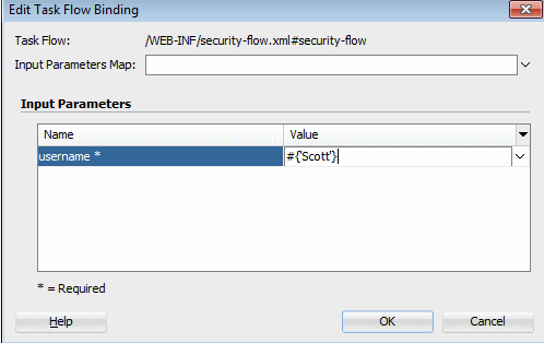
In the Edit Task Flow Binding, in the Value field, enter #{'Scott'}.
-
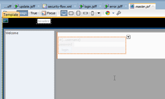
The master page should now look like the following:
-
Click the Save All
 icon to save the application.
Now that the task flow is integrated as a region to the master page you can run it. To do this, perform the following steps:
-
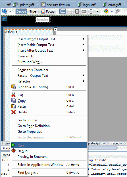
In the editor for the master page, right click and select Run from the context menu.
-
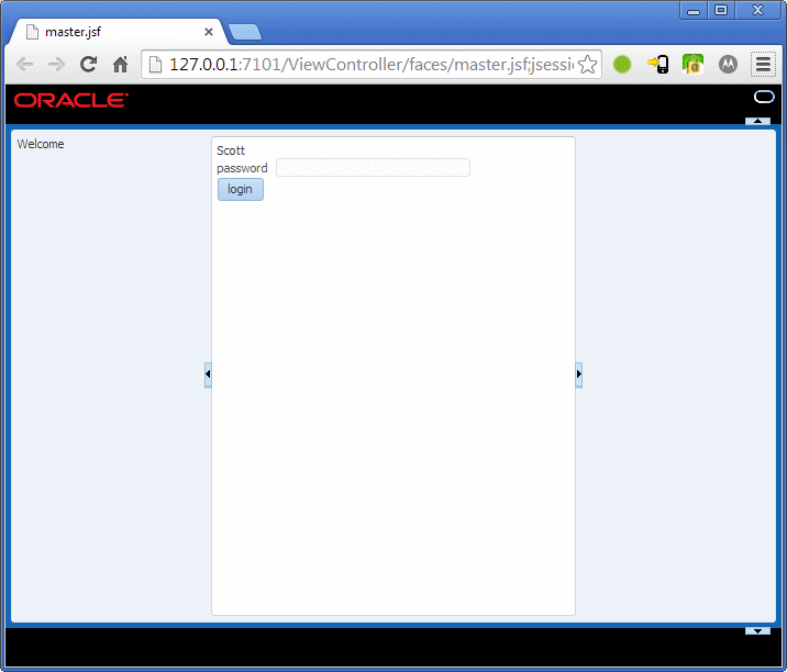
The page loads in your browser displaying the username variable (Scott) and waiting for a password to be typed in.
-
Try entering a wrong password value (different from oracle).
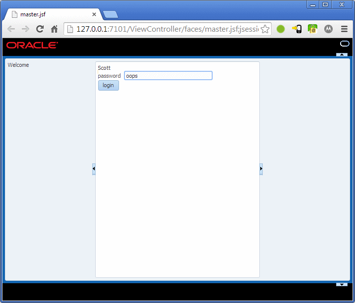
Then click the login button. The router drives you to the error page. -
Click the Retry button to logon with the correct password.
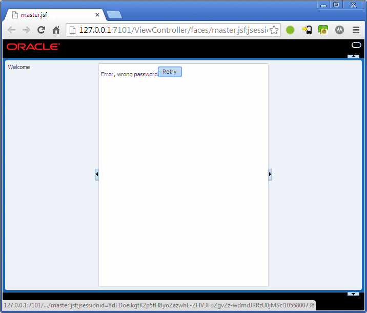
-
Back in the login page, enter oracle as the password value.
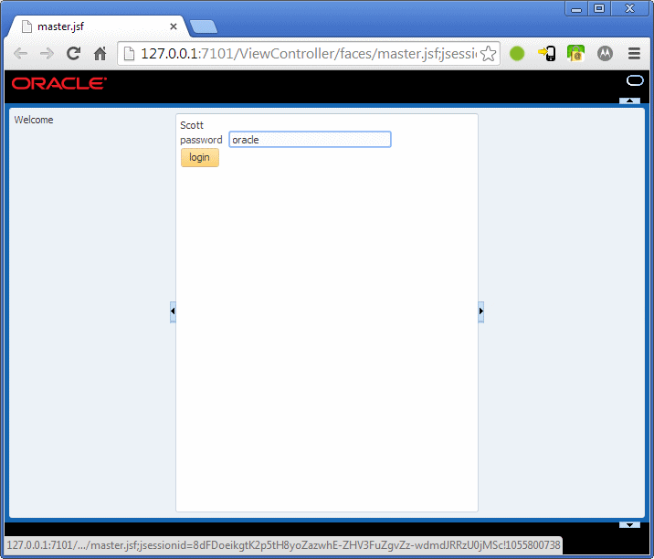
Then click login.
-
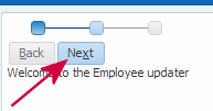
The new page appears displaying the train.
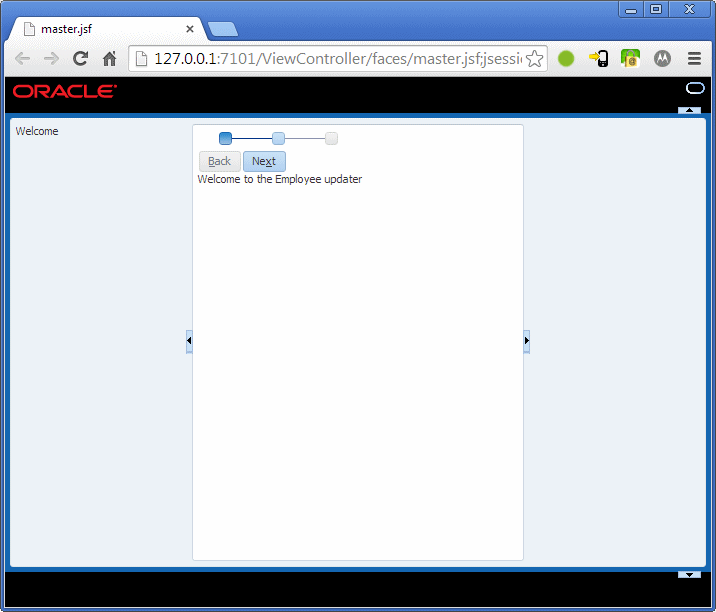
-
In the new page, click the Next button or the second button on the train.
-
In the second step of the train, in the search page, select LastName.
Enter A% in the search field to retrieve all employee's name starting with an A.
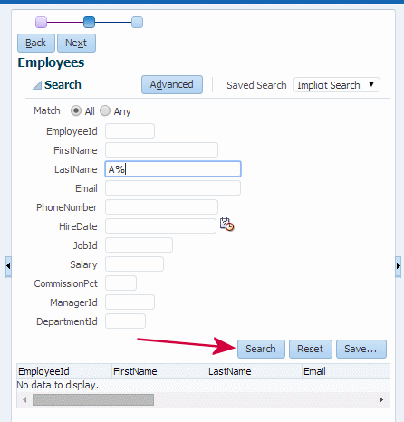
Click the search button. -
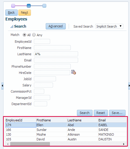
In the returned list, select one employee of your choice and then click the Next button.
You can collapse the Search panel, until you are ready to enter new criteria.
-
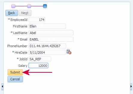
In the Edit page for the selected employee, update the salary to the value of your choice, then click Submit.
-
The application takes you back to the login page.
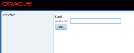
-
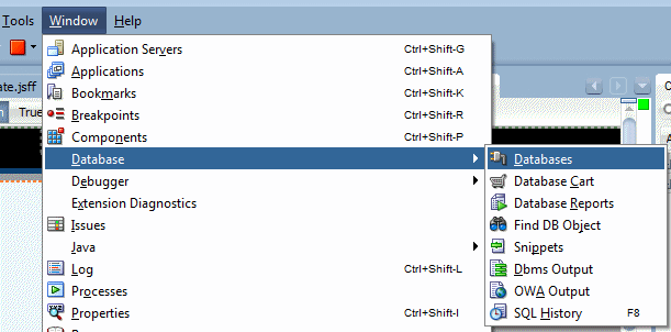
Switch back to JDeveloper and open the Database Navigator (if not visible, use Window > Database > Databases).
-
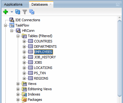
Expand the TaskFlow > HRConn > Tables nodes and double click the Employees table to open it.
-
Click the Data tab to display employee's values.
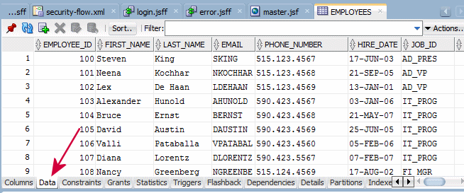
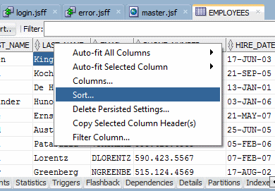
Right-click the header for the LAST_Name column and then from the context menu, select Sort.
-
To retrieve more easily the information about the employee you're looking for, you can use the Filter field or use a Sort operation. Click the Sort button and in the Sort Columns dialog, move LAST_NAME in the Selected Columns pane.
Then click OK.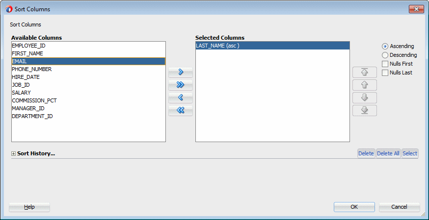
-
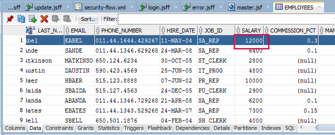
Locate the employee you've updated the salary to confirm that the update is committed with the new value.
-
You can reiterate this last process to test the Cancel (rollback) action.
You've successfully completed this tutorial.
- Create the Model Components
- Create a bounded task flow diagram
- Build the task flow pages
- Bind the task flow pages to data controls
- Set the transaction control to the task flow
- Define a second task flow
- Define the task flow components and the router rules
- Create the JSF Page and Bind the Task Flow as a Region to the page
- Developing Fusion Web Applications with Oracle Application Development Framework
- Creating ADF Task Flows
- Developing Applications with Oracle JDeveloper


