Q Monitoring NATed Traffic
This appendix provides information about how accurate network traffic reporting can be obtained if the RUEI system is placed after a Network Address Translation (NAT) device.
Q.1 Placement Before NAT Devices
As explained in the Oracle Real User Experience Insight Installation Guide, it is critically important that RUEI can see a copy of the network traffic. This can be obtained by using a copy/SPAN port or a TAP device.
Figure Q-1 outlines a typical configuration of cascaded devices. While the number of devices can vary from that shown, the sequence is typically that indicated. Sometimes, the firewall, SSL offloader (in the case of SSL encrypted traffic), and load balancer functions are combined into one or two components.
Figure Q-1 Placement of Monitoring Device
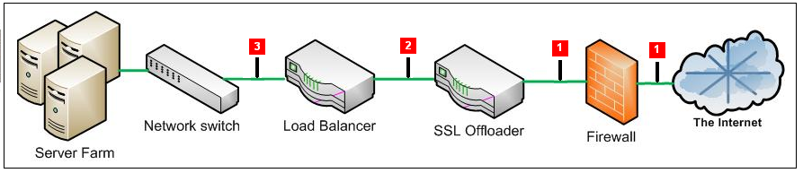
Description of ''Figure Q-1 Placement of Monitoring Device''
In most networks, there are three potential monitoring positions: directly behind (or in front of) the firewall, directly behind the SSL offloader, and directly behind the load balancer. These are indicated in Figure Q-1. The implications of the three candidate monitoring positions is outlined in Table Q-1.
Table Q-1 Monitoring Position Characteristics
| Position | Server info available | Client info available | SSL certificates required |
|---|---|---|---|
|
1 |
Only if in header reply |
Yes |
YesFoot 1 |
|
2 |
Only if in header reply |
Yes |
No |
|
3 |
Yes |
Only if delivered from NAT device in request header |
No |
Footnote 1 Note any deployment in front of an SSL offloading point will require the uploading of the SSL keys to the RUEI Collector system(s). This is necessary for RUEI to be able to decrypt the SSL traffic.
For Internet services, the load balancer is listening on the port where external clients connect to access services. It forwards requests to one of the back-end servers, which usually replies to the load balancer. This allows the load balancer to reply to the client without the client ever knowing about the internal separation of functions. It also prevents clients from contacting back-end servers directly, which may have security benefits by hiding the structure of the internal network.
It is recommended a RUEI system is placed in front of any Network Address Translation (NAT) devices. This ensures RUEI is immediately apply to see the originating IP address of the end user on TCP level. While the configuration shown in Figure Q-1 can differ between different networks, it is typically the load balancer device that performs NAT.
If RUEI is deployed in a network segment where end-user IP address translation has already taken place, and the configuration procedure described in the following section is not implemented, then the only reported end-user IP address will be the single IP address of the NAT device. While this does not negatively effect the accuracy of the reported data, it does mean that geographic and ISP client information is not available.
Note:
Be aware the RUEI monitoring position should always be after any VPN/decompression devices. This is because RUEI cannot read non-HTTP traffic between the encryption and decryption devices.Note:
Different devices have different effects on RUEI data collection, and network performance metrics or server performance metrics data may be lost depending on the monitoring position. In general, position 1 of Figure Q-1 provides the best client network performance data, whereas position 3 provides the best server network performance data. For example, if you decide to use position 3 as the RUEI location, measurements of page delivery can occur before the page is delivered to the client browser. This can result in RUEI reporting incorrect (too short) network time.Q.2 Obtaining the End-User IP Address
As explained earlier, obtaining the original end-user IP address is necessary for accurate geographical and ISP client reporting. Within RUEI, the IP address is normally obtained from the IP header packet sent from the client. The IP packet contains, among other things, the numerical source and destination address of the packet. However, if RUEI has been placed after a NAT device, this IP packet will contain the IP address of the NAT device, and not the end-user IP address.
Fortunately, the original (end-user) IP address is normally preserved in the HTTP header sent from the NAT device to the Web server. In this case, you can specify that RUEI should look in this header for the IP address, rather than the IP packet.
To specify the use of an HTTP header, instead of the IP packet, do the following:
-
Select Configuration, then Applications, and then Applications. Click the required application. Alternatively, selected the required suite or service. An overview of it appears.
-
Click the Advanced tab, and then the Client IP tab.
-
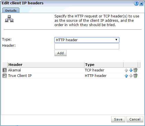
If no headers have been defined, click the Specify HTTP header(s) item. Alternatively, click Edit. The dialog shown in Figure Q-2 appears.
-
Select the Type of header you want to add. A HTTP header is derived from the HTTP request, and a TCP header is derived from a TCP options field. Currently the only TCP header available is Akamai, which is used when forwarding SSL-encrypted traffic.
-
Use the Header field to specify the request header(s) from which the client IP address should be retrieved. When ready, click Add. In the case of multiple headers, use the Move up and Move down controls to specify the order in which they should be tried. In the example shown in Figure Q-2, the Akamai header is first searched. If not available, the HTTP proxy client IP header is used. When ready, click Save.
Note that if the client IP address cannot be derived from any of the specified request headers, it is retrieved from the IP header packet. Any changes you make to the client IP address source setting will become visible in RUEI after five to 10 minutes. In addition, any changes only apply to currently collected data, and not to historical data.If RUEI is deployed behind a NAT device, you are strongly recommended to check and verify with both application and infrastructure management teams the appropriate manner to collect the End-User IP address from an HTTP header.
Q.3 Obtaining the IP Address of the Replying Web Server
Sometimes, it is also useful to see the replying server's IP address. For example, if an issue with slow or failing pages develops on a server farm, it is much quicker to resolve the issue if the relevant server's IP address is immediately visible.
This can be achieved inserting the replying server's IP address (or other identification information) into the header sent back to the load balancer.
Figure Q-3 shows an example of an HTTP header. It is taken from Mozilla Firefox's Live HTTP Headers plug-in, and shows how the original Web server identification (www236) has been moved into the HTTP header.
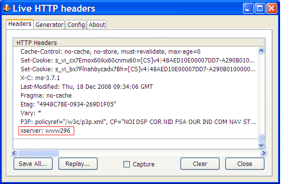
In this example, the header element is called xserver. It can be captured through the use of a custom dimension. This is fully described in Section 3.12, "Working With Custom Dimensions".