Figure: 1 Controller wiring diagram (management connectivity)
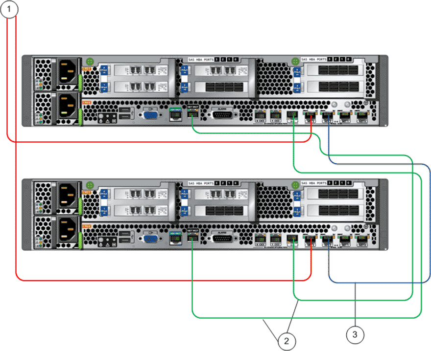
- Legend
1 NET 3 port to the Pilot NET 1 port 3 NET 2 port to NET 2 port 2 Cluster interconnect network port (labeled as <- - - >) to NET MGT port
The following figure illustrates the cabling for SAN connectivity to the customer data network.
Figure: 2 Controller wiring diagram (customer data network)
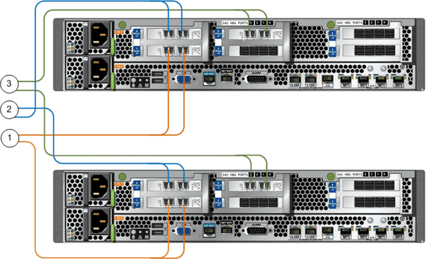
- Legend
1 PCIe3 slot 1, HBA for SAN connectivity (FC only) 3 PCIe3 slot 5, HBA for SAN connectivity (FC only) 2 PCIe3 slot 4, HBA for SAN connectivity (FC only)
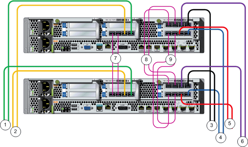
SAS Wiring Diagrams (Controller to Controller)
The SAS connections between the Controller HBAs provide access to the data path channels through HBA port 2 and port 3.
Controller 1 accesses the data path channels for I/O module 0 through direct SAS connections to the Drive Enclosure strings through HBA port 1 and port 2.
Controller 1 accesses the data path channels for I/O module 1 through Controller 2, HBA port 2 and port 3.
Controller 2 accesses the data path channel for I/O module 1 through direct SAS connections to the Drive Enclosure strings through HBA port 1 and port 2.
Controller 2 accesses the data path channels for I/O module 0 through Controller 1, HBA port 2 and port 3.
Figure: 3 SAS wiring diagram (Controller to Controller)
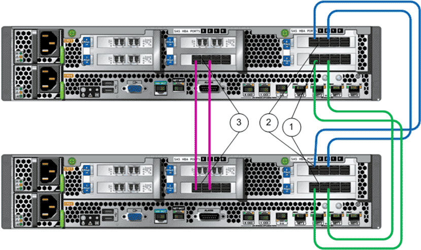
- Legend
1 PCIe3 slot 3, SAS HBA port 2 and port 3 3 PCIe3 slot 2, SAS HBA port 2 and port 3 2 PCIe3 slot 6, SAS HBA port 2 and port 3
SAS Wiring Diagrams (Controllers to Drive Enclosures)
All of the SAS cables that connect Controller 1 to the Drive Enclosures attach to I/O module 0, port 0 on the Drive Enclosures. All of the SAS cables that connect Controller 2 to the Drive Enclosures attach to I/O module 1, port 0 on the Drive Enclosures
Figure: 4 SAS wiring diagram for Controllers to Drive Enclosures (base)
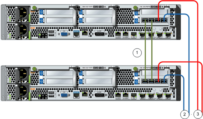
- Legend
1 PCIe3 slot 3, SAS HBAs port 2 and port 3 connect the Controllers 3 PCIe3 slot 3, SAS HBAs port 1 connects to Drive Enclosure string 2 2 PCIe3 slot 3, SAS HBAs port 0 connects to Drive Enclosure string 1
Figure: 5 SAS wiring diagram for Controllers to Drive Enclosures (performance)
- Legend
1 PCIe3 slot 2, SAS HBAs port 0 connects to Drive Enclosure string 3 6 PCIe3 slot 6, SAS HBAs port 1 connects to Drive Enclosure string 5 2 PCIe3 slot 2, SAS HBAs port 1 connects to Drive Enclosure string 6 7 PCIe3 slot 2, SAS HBAs port 2 and port 3 connect the Controllers 3 PCIe3 slot 6, SAS HBAs port 0 connects to Drive Enclosure string 2 8 PCIe3 slot 6, SAS HBAs port 2 and port 3 connect the Controllers 4 PCIe3 slot 3, SAS HBAs port 0 connects to Drive Enclosure string 1 9 PCIe3 slot 3, SAS HBAs port 2 and port 3 connect the Controllers 5 PCIe3 slot 3, SAS HBAs port 1 connects to Drive Enclosure string 4