Proper routing of cables allows for maintenance of the Oracle FS System without the need to remove the cables. Routing cables properly also helps prevent damage to the Oracle FS System components during maintenance.
All of the Pilot and the Controller cables, as well as the power cords, route through the cable management arms (CMAs). Routing cables through the CMAs helps assure clear access to all of the replaceable units inside of the chassis after the cover is removed.
Each CMA has Velcro straps and three latching bails that secure the cables. Route cables through the CMAs so that the chassis can be extended into the service position without interference from the cables. If you cannot extend the chassis into the service position, you will not be able to access the field replaceable units (FRUs) and customer replaceable units (CRUs) inside of the chassis. Additionally, if the cables become snagged while a chassis is extended into the service position, damage to the motherboard can occur.
Figure 1: Controller cables routed through the CMA
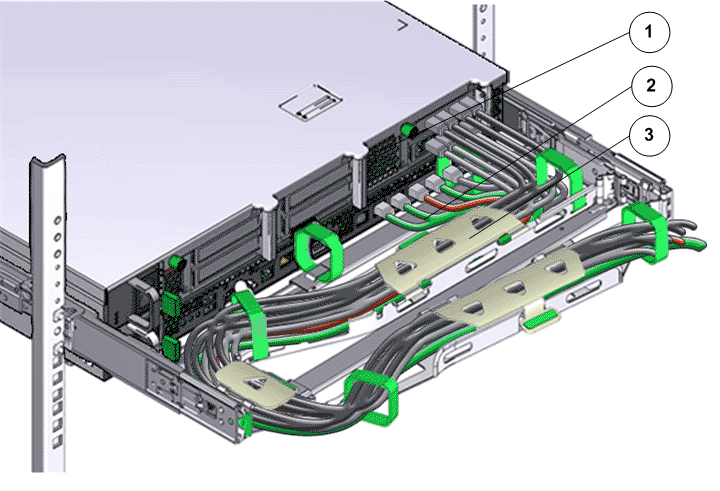
- Legend
1 Back of a Controller 3 CMA 2 Controller cables
Figure 2: Pilot cables routed through the CMA
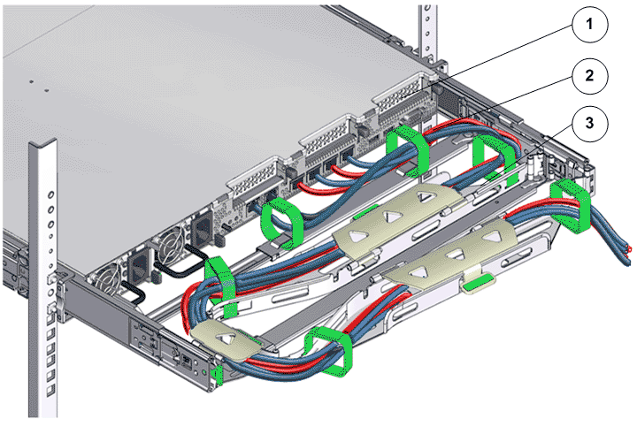
- Legend
1 Back of a Pilot 3 CMA 2 Pilot cables
When connecting the Controller nodes to the Drive Enclosures, start at the Controller end of the cable and route the SAS cable through the CMA. Then, run the cable vertically down the side of the rack and connect the cable to the Drive Enclosure. All of the SAS cables from the Controller CMAs are routed up or down the right-side vertical rail to the elevation of the target Drive Enclosures. The cables are then routed horizontally to the target Drive Enclosures.
Route and secure the SAS cables connecting one Drive Enclosure to another Drive Enclosure to either side of the rack. If cable management hooks are available in sides of the rack, you can secure the Drive Enclosure cables to the cable management hooks. Use Velcro cable ties to secure the Drive Enclosure cables to the sides of the rack.
Figure 3: Routing a cable same rack (Controller to Drive Enclosure)
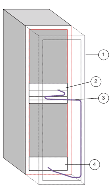
- Legend
1 Back of a rack 3 CMA 2 Controller 4 Drive Enclosure
Spool the excess cable length at the bottom of the rack and slide the cable between the rack rail and the side panel. Use an anchor point that is not a FRU, CRU, or another cable.
Identify an open space between the rack rail and the side panel and spool the excess cable length so that it can occupy the open space. Use an anchor point that is not a FRU, CRU, or another cable.