5 About Cartridge Modeling
This chapter explains how the Oracle Communications Network Integrity Optical TMF814 CORBA cartridge models collected data.
About Cartridge Modeling
The Oracle Communications Network Integrity Optical TMF814 CORBA cartridge models collected data according to the Oracle Communications Information Model. Collected data is modeled into the following entities:
-
DeviceInterfaceConfiguration
-
DeviceInterfaceConfigurationItem
-
Equipment
-
EquipmentHolder
-
EquipmentEquipmentRel
-
EquipmentHolderEquipmentRel
-
InventoryGroup
-
LogicalDevice
-
MediaInterface
-
PhysicalDevice
-
PhysicalDeviceEquipmentRel
-
PhysicalPort
-
Pipe
-
PipeTerminationPoint
-
PipePipeTerminationPointRel
See Oracle Communications Information Model Reference for more information about the Information Model.
About the Oracle Communications Information Model
The Information Model has Physical and Logical Tree models. Physical device hierarchy is modeled in the Physical Tree. Logical device hierarchy is modeled in the Logical Tree.
This section details how the Multi Technology Network Management (MTNM) model is mapped to the Information Model.
About the Physical Tree
Table 5-1 shows how MTNM objects are mapped to Physical Tree entities.
Table 5-1 MTNM to Information Model Mapping for Physical Tree
| MTNM Object | Information Model Entity | Specification |
|---|---|---|
|
Manage Element (ME) |
Physical Device |
tmf814MEGeneric |
|
Equipment Holder (Rack) |
Equipment |
tmf814EquipmentGeneric |
|
Equipment Holder (Shelf) |
Equipment |
tmf814EquipmentGeneric A shelf is modeled as Equipment since the Information Model does not allow a holder within a holder. |
|
Equipment Holder (sub Shelf) |
Equipment |
tmf814EquipmentGeneric |
|
Equipment Holder (Slot) |
Equipment Holder |
tmf814EquipmentHolderGeneric |
|
Equipment Holder (Sub Slot) |
Equipment Holder |
tmf814EquipmentHolderGeneric |
|
Equipment (Card) |
Equipment |
tmf814EquipmentGeneric |
|
Physical Termination Point (PTP) |
Physical Port |
tmf814PortGeneric |
|
Topological Link |
Pipe |
tmf814TopologicalLinkGeneric |
|
aEndTP, zEndTP (of a topological link object) |
PipeTerminationPoint |
tmf814PortTerminationPointGeneric |
|
Cross-connect |
InventoryGroup |
tmf814XCGeneric |
|
aEndName, zEndName (of a cross-connect |
Pipe |
tmf814XCSegmentGeneric A pair of related aEndName and zEndName objects are treated as a cross-connect segment. |
|
aEndName, zEndName (of a cross-connect segment) |
PipeTerminationPoint |
tmf814PortTerminationPointGeneric |
About the Logical Tree
Logical devices are created as root objects. Root objects are placeholder objects for top-level interfaces. PTPs and floating termination points (FTPs) are modeled as Device Interfaces. Contained termination points (TPs) of a PTP or FTP are modeled as sub-device-interfaces of a PTP or FTP device interface.
TPs that are discovered by the TMF814 API are modeled in the Logical Tree according to the following structure:
Logical Device (container for top level device interfaces){1}
Device Interface (Device Interface corresponding to PTP/FTP) {0...*}
Sub Device Interface (CTPs of PTP/FTP) {0...*}
Sub Device Interface (child CTPs with infinite nesting) {0...*}
Layer parameters of a TP are modeled using the DeviceInterfaceConfigurationItem interface and its child interface configuration items. This cartridge models only Generally Applicable Parameters, which are defined and explained in the TMF814 documentation.
Each TP layer is represented by the DeviceInterfaceConfigurationItem interface. All TP layers are contained in an artificial parent DeviceInterfaceConfigurationItem interface, as shown in the following example:
Device Interface (represents a CTP/PTP/FTP)
DeviceInterfaceConfigurationItem (just a container configuration item){1}
DeviceInterfaceConfigurationItem (one configuration item per layer rate){0..*}
Table 5-2 shows how MTNM objects are mapped to Information Model entities in the Logical Tree.
Table 5-2 MTNM-to-Information Model Mapping for Logical Tree
| MTNM Object | Information Model Entity | Specification |
|---|---|---|
|
ME |
LogicalDevice (artificial) |
tmf814DeviceGeneric Logical device acts as a container for top level interfaces. Its name is same as ME name. |
|
PTP |
DeviceInterface |
tmf814TPInterfaceGeneric PTP as Interface is a container for child CTP. |
|
FTP |
DeviceInterface |
tmf814TPInterfaceGeneric FTP as Interface is a container for child CTP. |
|
Connection Termination Point (CTP) |
DeviceInterface |
tmf814TPLayersGeneric CTP is a channel and is modeled as a sub Device Interface. |
|
LayeredParameters |
DeviceInterfaceConfigurationItem |
Managed Element Layered Parameters are modeled as configuration items of a Device Interface. |
Field Mapping
The following tables explain the field mappings for each Information Model object.
Table 5-3 Physical Device Field Mapping
| Information Model Attribute | Information Model Support | TMF Attribute | Type | UI Label |
|---|---|---|---|---|
|
Id |
Static |
N/A |
Text |
ID |
|
name |
Static |
name |
Text |
Name |
|
description |
Static |
N/A |
Text |
Description |
|
specification |
Static |
N/A |
PhysicalDeviceSpecification Programmatically set to tmf814MEGeneric specification. |
TMF814 MEGeneric |
|
discoveredVendorName |
Dynamic |
manufacturer |
Text Comes from additional information (not a TMF attribute). |
Discovered Vendor Name |
|
serialNumber |
Static |
N/A |
Text |
Serial Number |
|
physicalLocation |
Static |
location |
Text |
Physical Location |
|
softwareRev |
Dynamic |
version |
Text |
Software Version |
|
modelName |
Dynamic |
productName |
Text |
Model Name |
|
nativeEmsName |
Static |
nativeEmsName |
Text |
Native EMS Name |
|
userLabel |
Dynamic |
userLabel |
Text |
Label |
|
owner |
Dynamic |
owner |
Text |
Owner |
Table 5-4 Equipment Field Mapping
| Information Model Attribute | Information Model Support | TMF Attribute | Type and Values | UI Label |
|---|---|---|---|---|
|
Id |
Static |
N/A |
N/A |
ID |
|
name |
Static |
name |
Text |
Name |
|
description |
Static |
N/A |
Text |
Description |
|
specification |
Static |
N/A |
EquipmentSpecification Programmatically set to tmf814EquipmentGeneric specification. |
TMF814 Equipment Generic (displayed as Entity Type) |
|
discoveredVendorName |
Dynamic |
manufacturer |
Text Comes from additional information (not a TMF attribute). |
Discovered Vendor Name |
|
serialNumber |
Static |
installedSerialNumber |
Text |
Serial Number |
|
physicalLocation |
Static |
N/A |
Text |
Physical Location |
|
discoveredPartNumber |
Dynamic |
installedPartNumber |
Text |
Discovered Part Number |
|
hardwareRev |
Dynamic |
installedVersion |
Text |
Hardware Rev |
|
modelName |
Dynamic |
installedEquipmentObjectType |
Text |
Model Name |
|
nativeEmsName |
Static |
nativeEmsName |
Text |
Native EMS Name |
|
expectedObjectType |
Dynamic |
expectedEquipmentObjectType |
Text |
Expected Object Type |
|
serviceState |
Dynamic |
serviceState |
List: IN_SERVICE, OUT_OF_SERVICE, IN_MAINTENANCE, UNKNOWN, TESTING Each value corresponds to a TMF814 value: IN_SERVICE, OUT_OF_SERVICE, OUT_OF_SERVICE_BY_MAINTENANCE, SERV_NA. TMF814 does not have equivalent for TESTING. |
Service State |
|
userLabel |
Dynamic |
userLabel |
Text |
Label |
|
owner |
Dynamic |
owner |
Text |
Owner |
Table 5-5 EquipmentHolder Field Mapping
| Information Model Attribute | Information Model Support | TMF Attribute | Type | UI Label |
|---|---|---|---|---|
|
Id |
Static |
N/A |
Text |
ID |
|
name |
Static |
name |
Text |
Name |
|
description |
Static |
N/A |
Text |
Description |
|
specification |
Static |
N/A |
EquipmentHolderSpecification Programmatically set to tmf814EquipmentHolderGeneric specification. |
TMF814 Equipment Holder Generic (displayed as Entity Type) |
|
serialNumber |
Static |
N/A |
Text |
Serial Number |
|
physicalLocation |
Static |
N/A |
Text |
Physical Location |
|
modelName |
Dynamic |
expectedOrInstalledEquipment |
Text |
Model Name |
|
nativeEmsName |
Static |
nativeEmsName |
Text |
Native EMS Name |
|
userLabel |
Dynamic |
userLabel |
Text |
Label |
|
owner |
Dynamic |
owner |
Text |
Owner |
Table 5-6 Physical Port Field Mapping
| Information Model Attribute | Information Model Support | TMF Attribute | Type | UI Label |
|---|---|---|---|---|
|
Id |
Static |
N/A |
Text |
ID |
|
name |
Static |
name |
Text /rack=1/shelf=1/slot=3/domain=sdh/port=1 |
Name |
|
description |
Static |
N/A |
Text |
Description |
|
specification |
Static |
N/A |
PhysicalPortSpecification Programmatically set to tmf814PortGeneric specification. |
TMF814 Port Generic (displayed as an Entity Type) |
|
portNumber |
Static |
N/A |
Integer |
Port Number |
|
customerPortName |
Static |
N/A |
Text |
Customer Port Name |
|
vendorPortName |
Static |
N/A |
Text |
Vendor Port Name |
|
serialNumber |
Static |
N/A |
Text |
Serial Number |
|
physicalLocation |
Static |
N/A |
Text |
Physical Location |
|
nativeEmsName |
Static |
N/A |
Text |
Native EMS Name |
|
direction |
Dynamic |
direction |
List: NA, BIDIRECTIONAL, SOURCE, SINK |
Direction |
|
tpProtectionAssociation |
Dynamic |
tpProtectionAssociation |
List: TPPA_NA, TPPA_PSR_RELATED |
Protection Association |
|
edgePoint |
Dynamic |
edgePoint |
boolean |
Edge Point |
|
physicalAddress |
Static |
String |
Text |
Physical Address |
Table 5-7 Logical Device Field Mapping
| Information Model Attribute | Information Model Support | TMF Attribute | Type and Values | UI Label |
|---|---|---|---|---|
|
Id |
Static |
N/A |
Text |
ID |
|
name |
Static |
name |
Text |
Name |
|
description |
Static |
N/A |
Text |
Description |
|
specification |
Static |
N/A |
LogicalDeviceSpecification |
TMF814 Device Generic (displayed as Entity Type) |
|
nativeEmsAdminServiceState |
Static |
N/A |
List: UNKNOWN, IN_SERVICE, OUT_OF_SERVICE, TESTING, IN_MAINTENANCE |
Native EMS Admin Service State |
|
nativeEmsServiceState |
Static |
N/A |
List: UNKNOWN, IN_SERVICE, OUT_OF_SERVICE, TESTING, IN_MAINTENANCE |
Native EMS Service State |
|
nativeEmsName |
Static |
nativeEmsName |
Text |
Native EMS Name |
|
physicalLocation |
Static |
N/A |
Text |
Physical Location |
Table 5-8 Device Interface Field Mapping
| Information Model Attribute | Information Model Support | TMF Attribute | Type and Values | UI Label |
|---|---|---|---|---|
|
Id |
Static |
N/A |
Text |
ID |
|
name |
Static |
name |
Text |
Name |
|
description |
Static |
N/A |
Text |
Description |
|
specification |
Static |
N/A |
DeviceInterfaceSpecification Programmatically set to tmf814TPInterfaceGeneric specification. |
TMF 814 TPInterface Generic (displayed as Entity Type) |
|
ifType |
Static |
Tp_type |
List: CTP, PTP, FTP |
Interface Type |
|
interfaceNumber |
Static |
N/A |
Text |
Interface Number |
|
customerInterfaceNumber |
Static |
N/A |
Text |
Customer Interface Number |
|
vendorInterfaceNumber |
Static |
N/A |
Text |
Vendor Interface Number |
|
nativeEmsName |
Static |
N/A |
Text |
Native EMS Name |
|
nativeEmsAdminServiceState |
Static |
N/A |
List: UNKNOWN, IN_SERVICE, OUT_OF_SERVICE, TESTING, IN_MAINTENANCE |
Native EMS Admin Service State |
|
nativeEmsServiceState |
Static |
N/A |
List: UNKNOWN, IN_SERVICE, OUT_OF_SERVICE, TESTING, IN_MAINTENANCE |
Native EMS Service State |
|
mtuSupported |
Static |
N/A |
Float |
Supported MTU |
|
mtuCurrent |
Static |
N/A |
integer |
Current MTU |
|
physicalAddress |
Static |
N/A |
Text |
Physical Address |
|
physicalLocation |
Static |
N/A |
Text |
Physical Location |
|
minSpeed |
Static |
N/A |
Float |
Minimum Speed |
|
maxSpeed |
Static |
N/A |
Float |
Maximum Speed |
|
nominalSpeed |
Static |
N/A |
Float |
Nominal Speed |
|
connectionState |
Dynamic |
connectionState |
List: TPCS_BI_CONNECTED, TPCS_NA, TPCS_SOURCE_CONNECTED, TPCS_SINK_CONNECTED, TPCS_BI_CONNECTED, TPCS_NOT_CONNECTED |
Connection State |
|
tpMappingMode |
Dynamic |
tpMappingMode |
List: TM_NA (0), TM_NEITHER_TERMINATED_NOR_AVAILABLE_FOR_MAPPING (1), TM_TERMINATED_AND_AVAILABLE_FOR_MAPPING (2) |
Termination Mode |
|
direction |
Dynamic |
direction |
List: NA, BIDIRECTIONAL, SOURCE, SINK |
Direction |
|
tpProtectionAssociation |
Dynamic |
tpProtectionAssociation |
List: TPPA_NA, TPPA_PSR_RELATED |
Protection Association |
|
edgePoint |
Dynamic |
edgePoint |
Boolean |
Edge Point |
|
userLabel |
Dynamic |
userLabel |
Text |
Label |
|
owner |
Dynamic |
owner |
Text |
Owner |
|
nativeEmsConnectorPresent |
Static |
N/A |
Text |
Native EMS Connector Present |
Table 5-9 DeviceInterfaceConfigurationItem Field Mapping
| Information Model Attribute | Information Model Support | TMF Attribute | Type and Values | UI Label |
|---|---|---|---|---|
|
name |
Static |
N/A |
Text Name is always set to LayerName |
Name |
|
value |
Static |
Layer |
Text |
Value |
|
specification |
Static |
InventoryConfigurationSpec |
Text Programmatically set to tmf814TPLayersGeneric specification. |
TMF814 TPLayer Generic (displayed as Entity Type) |
|
clientType |
Dynamic |
clientType |
Text |
Client Type |
|
potentialFutureSetupIndicator |
Dynamic |
potentialFutureSetupIndicator |
List: RSU_POINT_TO_POINT, RSU_BROADCAST, RSU_ANY_CONFIG |
Potential Future Setup Indicator |
|
serviceState |
Dynamic |
serviceState |
List: IN_SERVICE, OUT_OF_SERVICE, IN_MAINTENANCE, UNKNOWN, TESTING Each value is mapped to TMF814 specific values: IN_SERVICE, OUT_OF_SERVICE, OUT_OF_SERVICE_BY_MAINTENANCE, SERV_NA. TMF814 does not have equivalent for TESTING. |
Service State |
|
TCAParameterProfilePointer |
Dynamic |
TCAParameterProfilePointer |
Text |
TRA Parameter Profile Pointer |
|
trailTraceExpectedRx |
Dynamic |
trailTraceExpectedRx |
Text |
Trail Trace Expected Rx |
|
trailTraceMonitor |
Dynamic |
trailTraceMonitor |
Text |
Trail Trace Monitor |
|
transmissionDescriptorPointer |
Dynamic |
transmissionDescriptorPointer |
Text |
Transmission Descriptor Pointer |
|
allocatedNumber |
Dynamic |
allocatedNumber |
Number |
Allocated Number |
|
dynamicAllocationEnabled |
Dynamic |
dynamicAllocationEnabled |
Text |
Dynamic Allocation Enabled |
About Building the Information Model Tree
Collected TMF814 objects contain raw hierarchical details, but not at the object level. After the TMF814 objects are modeled as Information Model entities, they are added to the Physical or Logical Tree. This section describes the algorithm used for building the Trees.
Containment Relationships
To find containment relationship among discovered objects, the algorithm uses the Name attribute of TMF814 objects. The structure of the name is hierarchical and reflects the containment relationship between objects in a simple way. Table 5-10 describes the convention used for the field name.
Table 5-10 Name and Attribute Format for Containment Relationships
| TMF Object | Name/Value Pairs |
|---|---|
|
ME |
name="EMS"; value="CompanyName/EMSname" name="ManagedElement"; value="MEName" |
|
PTP |
name="EMS"; value="CompanyName/EMSname" name="ManagedElement"; value="MEName" name="PTP"; value="PTPName" |
|
FTP |
name="EMS"; value="CompanyName/EMSname" name="ManagedElement"; value="MEName" name="FTP"; value="FTPName" |
|
CTP, as child of a PTP or FTP |
name="EMS"; value="CompanyName/EMSname" name="ManagedElement"; value="MEName" name="PTP"; value="PTPName" name="CTP"; value="CTPName" name="FTP"; value="FTPName" |
|
EquipmentHolder |
name="EMS"; value="CompanyName/EMSname" name="ManagedElement"; value="MEName" name="EquipmentHolder"; value="EquipmentHolderName" |
|
Equipment |
name="EMS"; value="CompanyName/EMSname" name="ManagedElement"; value="MEName" name="EquipmentHolder"; value="EquipmentHolderName" name="Equipment"; value="EquipmentName" |
The Equipment Holder tuple values are hierarchical and have the following structure:
[/remote_unit=<ru>][/rack=<r>][/shelf=<sh>[/sub_shelf=<ssh>][/slot=<sl>[/[remote_]sub_slot=<ssl>]]]]
Adding an Equipment and an Equipment Holder to the Tree
The TMF814 Equipment Modeler processor is run for each EquipmentOrHolder TMF814 object. After modeling, the Equipment or Equipment Holder object is added to the Information Model Physical Tree.
It is possible that a child node can appear before its parent node is available. The algorithm handles this by using a placeholder node, which takes the place of the real node until the real node is available.
If the input object is a TMF814 Equipment Holder:
-
The EquipmentHolder tuple value is obtained from the name property. The tuple value is the hierarchical name of the Equipment Holder.
-
The name is split into two substrings at the last index of the / delimiter. This gives two placeholders:
-
The first placeholder gives the hierarchical name of the parent node, which is most likely another Equipment Holder.
-
The second placeholder is the shorter name for the Equipment Holder.
index = lastIndexOf(name , "/");
first = substring(name, 0, index)//First token
second = substring(name, index +1, name.length)
-
-
If the first placeholder is empty, the Equipment Holder is a top-level object, and thus a parent node. The parent node is the node representing the physical device in the Tree.
-
If first placeholder is not empty, the Physical Tree is hierarchically searched from the root until the node representing the full hierarchical name is found. A placeholder is created for it while the Physical Tree is being searched.
For example, if a placeholder is created for /rack=1/shelf=2/slot=3, it is split into /rack=1, /rack=1/shelf=2, and /rack=1/shelf=2/slot=3. The Physical Tree is searched for /rack=1. If it is found, the search continues for /rack=1/shelf=2. If it is not found, a placeholder is created for it. /rack=1/shelf=2/slot=3 is also not available, so a placeholder is created for it as well. The parent node is /rack=1/shelf=2/slot=3.
-
Parent nodes are verified to determine if they have any child nodes with a placeholder. If they do, the placeholder is released and is used for another node.
-
Nodes are created or replaced in the Physical Tree.
If the output object is TMF814 Equipment:
-
The EquipmentHolder tuple value is obtained from the name property.
-
The Physical Tree is hierarchically searched until the node representing the full hierarchical name is found. If the name is not found, a placeholder node is created for it.
For example, if a placeholder is created for /rack=1/shelf=2/slot=3, it is split into /rack=1, /rack=1/shelf=2, and /rack=1/shelf=2/slot=3. The Physical Tree is searched for /rack=1. If it is found, the search continues for /rack=1/shelf=2. If it is not found, a placeholder is created for it. /rack=1/shelf=2/slot=3 is also not available, so a placeholder is created for it as well. Parent node is /rack=1/shelf=2/slot=3.
-
Parent nodes are verified to determine if they have any child nodes with a placeholder. If they do, the placeholder is released and is used for another node.
-
Nodes are created or replaced in the Physical Tree.
After all nodes are modeled in the Physical Tree. Any remaining placeholder nodes are modeled as artificial objects.
Adding a Physical Port and an Interface to the Tree
TPs are modeled as physical ports. An associated artificial device interface is created for each physical port. A device interface is added as a direct child of a logical device.
The algorithm for adding equipment holders to the Tree can be applied to adding a physical port to the Physical Tree. See "Adding an Equipment and an Equipment Holder to the Tree" for more information.
Cartridge Modeling for Cross-Connect Data
This section explains how the Optical TMF814 CORBA cartridge models the collected cross-connect data.
Only the cross-connect data required for assimilation is modeled. Of the data required for assimilation, only the data meeting the following conditions is modeled:
-
At least one of aEnd or zEnd should have a non-null/empty value.
-
Both aEnd and zEnd should represent CTP or FTP names.
-
At least one of aEnd or zEnd should have JKLM (VC12), JK (VC3), or J (VC4) values.
The Optical TMF814 CORBA cartridge models cross-connects as one of the following types:
-
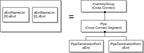
ST_SIMPLE: Cross-connects with only one segment, as shown in Figure 5-1.
Some vendors represent a bidirectional cross-connect as two unidirectional cross-connects, meaning one has A1-Z1 as its ends and other has Z1-A1 as its ends. Such cross-connects are modeled as bidirectional.
-
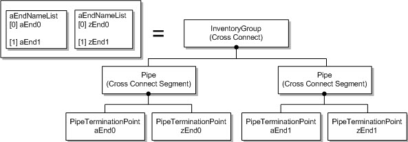
ST_EXPLICIT: The cross-connect object is modeled as multiple pipe objects, as shown in Figure 5-2.
The number of objects into which a single cross-connect is modeled depends on aEndNameList and zEndNameList size. The explicit subnetwork connection (SNC) type has an n-entry aEndNameList and zEndNameList pairing. The tuples are pairs matched by index, for example (A1,Z1), (A2, Z2), ...,(An,Zn). A pipe object is modeled for each pair. These multiple pipes are grouped by a parent Inventory Group object.
-
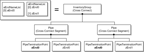
ST_ADD_DROP_A: The cross-connect object is modeled as two pipe segments with aEndPoint repeating on both cross-connects segment, as shown in Figure 5-3.
-
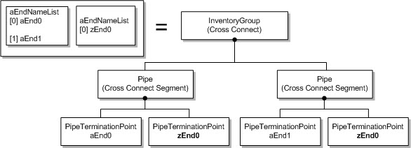
ST_ADD_DROP_Z: The cross-connect object is modeled as two pipe segments with zEndPoint repeating on both cross-connects segment, as shown in Figure 5-4.
Other cross-connects types, such as ST_INTERCONNECT, ST_DOUBLE_INTERCONNECT, ST_DOUBLE_ADD_DROP, and ST_OPEN_ADD_DROP are not modeled by this cartridge without extending the cartridge.
The following tables list the model mapping of cross-connect objects:
Table 5-11 Model Mapping for the Inventory Group Object
| Information Model Attribute | Information Model Support | TMF Attribute | Type | UI Label |
|---|---|---|---|---|
|
name |
Static |
N/A |
Text Value is hard-coded to Cross Connect |
Name |
|
layerRate |
Dynamic |
N/A |
Text |
Layer Rate |
|
type |
Dynamic |
ccType |
Text |
Type |
|
active |
Dynamic |
active |
Text |
Active |
Table 5-12 Model Mapping for the Pipe Object
| Information Model Attribute | Information Model Support | TMF Attribute | Type | UI Label |
|---|---|---|---|---|
|
name |
Static |
N/A |
Text |
Name |
|
gapPipe |
Static |
N/A |
Boolean, always set to True. |
Gap Pipe |
|
protectionRole |
Dynamic |
N/A |
Text The value is derived. Possible values are PRIMARY, BACKUP. |
Protection Role |
Table 5-13 Model Mapping for the PipeTerminationPoint Object
| Information Model Attribute | Information Model Support | TMF Attribute | Type | UI Label |
|---|---|---|---|---|
|
name |
Static |
N/A |
Text The name of the PTP (port) cross-connect end point. |
Name |
|
device |
Dynamic |
N/A |
Text |
Device |
|
directionality |
Dynamic |
N/A |
Text |
Directionality |
|
rate |
Dynamic |
N/A |
Text |
Layer Rate |
|
channel |
Dynamic |
N/A |
Text Channel values are derived. See "A and Z Channels" for more information. |
Channel |
A and Z Channels
The following example SDH implementation shows how the channel is calculated for each PipeTerminationPoint.
Example CTP Name JKLM tuples:
-
/sts3c_au4=4/vt2_tu12-k=1-l=3-m=2
-
/direction=src/sts3c_au4=4/vt2_tu12-k=1-l=3-m=2
-
/sts1_au3-j=2-k=2/vt15_tu11-l=1-m=2
JKLM values are collected from the CTPName tuple. Each CTP tuple can be split into a number of tokens separated by a slash. Each token can be further split into a number of subtokens separated by a hyphen.
If the CTPName tuple does not have any JKL or M value it is treated as a dropdown port.
Example 5-1 shows how the JKLM values are parsed. This example assumes that the aEnd and zEnd of a cross-connect are a CTP with the formatting shown below:
Example 5-1 Parsed JKLM Values
Pattern pattern = Pattern.compile("/");
Matcher subTokenMatcher = Pattern.compile("\\-j=\\d+|\\-k=\\d+|\\-l=\\d+|\\-m=\\d+").matcher("");
String STS3C_AU4 = "sts3c_au4=";

String[] jklm = new String[]{"0", "0", "0", "0"};
Scanner scaner = new Scanner(ctpName);
scaner.useDelimiter(pattern);
while(scaner.hasNext()){
    String token = scaner.next();
    subTokenMatcher.reset(token);
    while(subTokenMatcher.find()){
        String subToken = subTokenMatcher.group();
if(subToken.startsWith("-")){
            String val = token.substring(subTokenMatcher.start() +1, subTokenMatcher.end());
            jklm[val.charAt(0) % 106] = val.substring(2, val.length());
        }else{
            jklm[subToken.charAt(0) % 106] = subToken.substring(2, subToken.length());
        }
    }
    if(jklm[0].equalsIgnoreCase("0") && token.startsWith(STS3C_AU4)){
        jklm[0] = token.split("=")[1];;
    }
}
return jklm;
The Optical TMF814 CORBA cartridge can be extended to populate JKLM values that are implemented differently by some vendors. See "Customizing the JKLM Value Calculation" for more information.
Cartridge Modeling for Topological Link Data
This section explains how the Optical TMF814 CORBA cartridge models collected topological link data.
Topological links are modeled Information Model pipe entities. Topological Link endpoints (aEndTP and zEndTP) are modeled as pipe termination point entities.
Some vendors represent bidirectional topological links as two unidirectional topological links (two links sharing the same aEnd and zEnd ports). Such links are merged and modeled as one bidirectional topological link.
The following tables list the model mapping of topological link objects:
-
Table 5-14, "Model Mapping for the Pipe Object for Topological Links"
-
Table 5-15, "Model Mapping for the PipeTerminationPoint Object for Topological Links"
Table 5-14 Model Mapping for the Pipe Object for Topological Links
| Information Model Attribute | Information Model Support | TMF Attribute | Type | UI Label |
|---|---|---|---|---|
|
name |
Static |
N/A |
Text |
Name |
|
gapPipe |
Static |
N/A |
Boolean This value is always set to False for topological link objects. |
Gap Pipe |
|
layerRate |
Dynamic |
rate |
Text |
Layer Rate |
|
nativeEMSName |
Dynamic |
nativeEMSName |
Text |
Native EMS Name |
|
owner |
Dynamic |
owner |
Text |
Owner |
Table 5-15 Model Mapping for the PipeTerminationPoint Object for Topological Links
| Information Model Attribute | Information Model Support | TMF Attribute | Type | UI Label |
|---|---|---|---|---|
|
name |
Static |
name |
Text |
Name |
|
device |
Dynamic |
N/A |
Text The value is derived from the device. |
Device |
|
directionality |
Dynamic |
N/A |
Text |
Directionality |
|
rate |
Dynamic |
N/A |
Text This value is derived from the line layer rate for the endPort represented by the PortTerminationPoint. |
Layer Rate |
|
channel |
Dynamic |
N/A |
Text This attribute is not used. |
Channel |
Result Groups
Topological link pipe entities and cross-connect inventory group entities are both added to the same device result group, but in separate group containers.
Topological links span multiple devices. When the aEnd and zEnd ports are managed by MEs belonging to different EMSs, the topological link is modeled according to the device name that appears first in a sorted list.
The Link result group models a root entity container with the name Links as the parent for all topological links associated with a device. The topological link appears on the lower device of the two endpoints, as shown in Figure 5-5.
The cross-connect result group models a root entity container with the name Cross-connects as the parent for all cross-connects associated with the device, as shown in Figure 5-5.
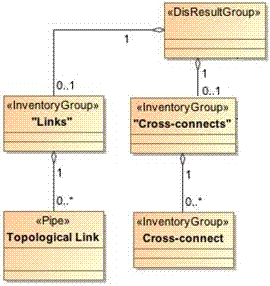
Figure 5-6 shows an example grouping for links and cross-connects with the following particularities:
-
A populated result group for each device
-
The appropriate cross-connects added to each device group
-
The topological link is added only to the ME1 device group
Figure 5-6 Example Result Group Model and Configuration
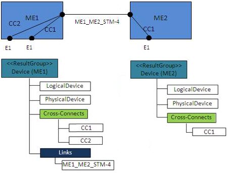
Description of ''Figure 5-6 Example Result Group Model and Configuration''