5 Designing a Messaging Server Topology
This chapter provides information on how to design your messaging topology. A messaging topology describes the physical and logical layout of a networked messaging system. Specifically, a topology depicts the way the devices are arranged on a network and how they communicate with one another. In addition, a topology describes the way that data passes through a network. Topologies are bound to network protocols that direct the data flow.
For information about Messaging Server topology with the Cassandra message store, see Messaging Server Installation and Configuration Guide for Cassandra Message Store.
Identifying Your Geographic Needs
The first step in designing your messaging topology is to identify your geographic needs. In particular, determine the messaging services you need to provide at each location within your organization:
-
Once you identify your deployment goals, determine the functions and features needed for each location within your deployment.
-
Understand your organization's physical constraints, specifically:
-
Available bandwidth
-
Distance between physical locations within your organization
-
Mail transaction rate and volume of mail storage at each physical location
-
Designing a Messaging Topology
Before you develop your topology, you need a strategy to determine where you are going to put your messaging servers in your organization. Depending on your goals, there are four common topologies that you can apply to your organization:
-
"Central Topology" consolidates most or all major system components and messaging servers at a single location.
-
"Distributed Topology" spreads most or all system components and messaging servers across multiple sites.
-
"Hybrid Topology" consolidates some system components and distributes other components across multiple locations.
-
"Service Provider Topology" hosts multiple domains and handles larger customer base. Like a central topology, it consolidates most system components at a single location.
Central Topology
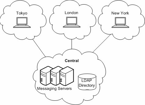
In a central topology, most or all major system components and messaging processes are located at one site. Clients at remote sites communicate over a Wide Area Network (WAN) to the centralized messaging servers. Figure 5-1 shows a central topology.
You should consider a central topology for your organization when:
-
Messaging at remote sites is not mission critical.
-
Users tend to send and receive small text messages.
-
Your organization is located in one physical location or distributed across many small user populations.
-
You do not have remote support personnel.
-
Good bandwidth exists between remote sites and the central site (at least ISDN or better).
There are advantages to implementing a central topology. In general, a central topology has lower hardware and support costs. Central topologies tend to be easier to manage because you have a simplified messaging architecture and a directory replication structure with fewer replication agreements. With a simplified architecture and no need to coordinate installation among geographically distant sites, a central topology is faster to deploy.
That said, there are an equal number of disadvantages to implementing a central topology. A centralized approach heavily relies on a WAN. If the network does not function properly, users at the same site as well as users in remote locations could not send email to one another. Depending on network bandwidth and traffic, services might be slower during peak usage times. For users who send messages within the same domain, a central topology is inefficient. For example, looking at Figure 5-1, a message sent from one user in the Tokyo site would first travel to the Central site before being sent to another user in the Tokyo site.
Distributed Topology
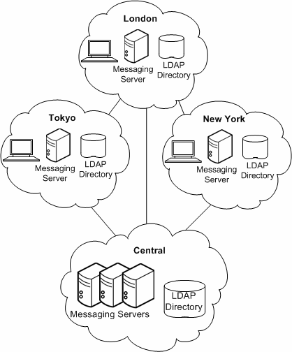
In a distributed topology, most or all system components and messaging processes are distributed across multiple sites, usually at each remote site. Figure 5-2 shows a distributed topology.
You should consider a distributed topology for your site when:
-
Messaging at remote sites is mission critical.
-
Users send and receive large messages.
-
You have large user populations at remote sites.
-
Support personnel exists at remote sites.
-
There is poor bandwidth to remote sites.
If bandwidth significantly impacts your topology strategy, you should consider upgrading the bandwidth. In general, bandwidth is relatively inexpensive. You might also consider a Virtual Private Networking (VPN), which uses existing high bandwidth Internet pipes rather than dedicated lines behind a firewall.
There are advantages to implementing a distributed topology. Users at regional sites have faster access to their messages because they do not have to retrieve messages over the WAN. Furthermore, messages sent within a regional location will incur less messaging traffic than in a central topology. However, satellite offices still rely on the WAN. Therefore, if lots of message traffic is generated in a satellite office, the WAN might need to be upgraded.
The disadvantages of implementing a distributed topology are that typically you will have higher hardware costs and higher support costs as you maintain more hardware at more locations. Support costs are also higher because of the complexity of the distributed topology. For example, failover in a distributed topology is more difficult to implement than in a central topology. In addition, it is much slower to initially deploy Oracle Communications Messaging Server because there are multiple servers spread across multiple sites.
Because Messaging Server accesses the LDAP directory, the LDAP server is a critical link in the mail delivery process. If you don't use remote LDAP replicas, and the central LDAP is down, the messaging service will not be usable.
Hybrid Topology
In a hybrid topology, central and distributed topologies are combined to meet the needs of an organization. Figure 5-3 shows a hybrid topology.
Organizations that benefit from a hybrid topology include those with many sites that have the ability to support a large user base. These sites that support them can house their own messaging servers. Some of these larger sites might have smaller satellite offices located in the general vicinity. But these satellite offices would not require their own messaging servers. Instead, the nearest major office would act as the central location for their services.
Service Provider Topology
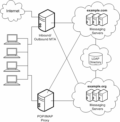
In essence, a service provider topology is a large-scale central topology. Typically, a service provider hosts multiple domains and has a larger customer base than an enterprise. Systems are centralized and are able to support multiple users during peak hours. Figure 5-4 shows a service provider topology.
Understanding Messaging Topology Elements
This section describes the most common elements in a messaging topology. Having some familiarity with the basic elements will make it easier for you to design your own topology.
The following topics are covered:
Messaging Topology Components
In "Designing a Messaging Topology," you were introduced to three components of a messaging topology: Messaging Server, Directory Server, and clients. This section will describe other components in a basic messaging topology.
-
Messaging Server. Houses and maintains user mailboxes; it can also be a server that contains just the MTA portion of Messaging Server as described in Internet-facing MTA and MTA Relay.
-
Client. Accesses messaging services from Messaging Server (often through the Messaging Multiplexor).
-
Directory Server. Used by Messaging Server for name and alias lookup. Direct LDAP lookup determines where messages should be routed.
-
Messaging Multiplexor. Connects clients to the appropriate Messaging Server for retrieving messages.
-
Internet-facing MTA. Routes messages from the Internet and relays them across the firewall. Typically, a Messaging Server host is set up to perform this function.
-
MTA Relay. The inbound MTA routes incoming messages to valid addresses in the appropriate Messaging Server. The outgoing MTA accepts outgoing messages from clients, queries LDAP to find out where to send the message, then sends it off to the appropriate server or out across the firewall to the Internet. Typically, a Messaging Server host is set up to perform this function.
-
DNS Server. Resolves server names into IP addresses to allow messages to be routed to their proper address in the network.
-
Firewall. Restricts Internet access of your internal site. You might even have a firewall between departments in your organization.
Using MTAs to Protect Your Messaging System
You can use MTAs to protect your Messaging Server deployment, as well as to control the flow of message traffic to and from your site.
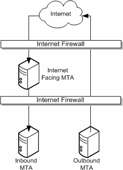
An Internet-facing MTA is a single point of contact that receives messages from sites external to your organization. An Internet-facing MTA sends the incoming messages across the firewall to the inbound MTA, typically another Messaging Server.
The inbound MTA then queries the directory to determine where to send the message within the organization. The Internet-facing MTA is located in the demilitarized zone (DMZ) of the firewall (between the external and internal walls of the firewall), and does not have access to any information about servers other than the inbound MTA.
The outbound MTA accepts outgoing messages from clients. It queries LDAP to find out where to send the message, then sends it off to the appropriate server or out across the firewall to the Internet. This offloads the MTA work from messaging servers that are used by users to retrieve messages. Figure 5-5 illustrates the idea.
Using MMPs
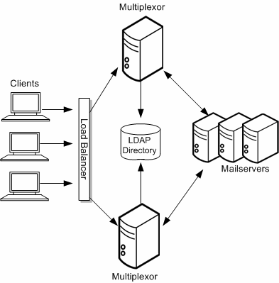
The MMP enables you to mask the layout of your Messaging Server hosts from your end users. Consequently, you assign users to a generic MMP or a load balancer without having them point to the specific server where their mail boxes reside. Message access clients point to the MMP for retrieving incoming messages.
When such a client connects and authenticates, the MMP looks up the user information in the directory to determine where the user's messages are held. The MMP then connects the client to that specific server. Figure 5-6 shows how the MMP acts as a proxy for IMAP4 and POP3 connections to messaging servers.
Use a load balancer in front of the multiple MMPs. It is unlikely that you would have a single MMP.
Using the MMP SMTP Proxy
Note:
Starting with Messaging Server 8.0.2, the SMTP submission proxy in the MMP is no longer supported.The MMP contains an SMTP proxy that is designed to accept messages but not transfer messages. Because of this design, never use the MMP SMTP Proxy as the target of a DNS MX record or to otherwise receive mail incoming from arbitrary sources on the Internet. Messaging Server does not support the use of the MMP SMTP Proxy in a message transfer capacity.
Messaging Server does support the use of the MMP SMTP proxy for message submission from end-user clients. However, the multiplexing functionality of the MMP, which is necessary to distribute POP and IMAP connections to the correct back-end store, is not necessary for SMTP submission. You can balance SMTP submission by MX records for mail clients that follow the standard, or by a simple load balancer for mail clients that do not follow the standard.
Only use the MMP SMTP Proxy in the following situations:
-
If the MTA is becoming impeded with SSL/TLS processing, the MMP SMTP proxy can offload that processing for message submission while still supporting standard SMTP STARTTLS.
-
If the MMP has SSL hardware acceleration for POP/IMAP, it might make sense to also leverage that for SMTP submission.
-
If you need to use the ”POP before SMTP” mechanism, then the MMP SMTP Proxy is required.
-
The MMP SMTP proxy has a desired feature not present in the back-end MTA.
-
If your deployment requires a proxy, then use the MMP SMTP proxy, which is specifically designed to preserve the security features and SMTP extensions present in the MTA and uses a custom SMTP extension (XPEHLO) to do so safely.
Note:
The MMP SMTP Proxy only works with Messaging Server's SMTP server as a back-end.Using Gateways
Your organization might contain legacy messaging systems that use proprietary methods for messaging handling. Until you migrate your users, both messaging strategies must co-exist. To access these legacy systems, you can use an SMTP gateway, which enables SMTP connections between the new system and the other legacy systems. Usually legacy systems support SMTP connections so that the inbound MTA can route messages to it.
Creating a Messaging Topology Example
Once you have a basic understanding of your topological needs, your strategy, and the topology elements, you can create your messaging topology. To illustrate how to create a messaging topology, this section uses the example of the Example Corporation.
The Example Corporation is a multimedia organization headquartered in New York, with two smaller offices in Los Angeles and Chicago, and two satellite offices in San Diego and in Minneapolis.
Step 1: Identifying Messaging Goals
The first step in creating a topology is to understand the goals of your organization. Example's messaging goals can be categorized into business objectives, technical, and financial constraints.
Example's Business Objectives
The finance, marketing, legal, IT, and engineering groups are located in New York. The creative groups are located in Los Angeles and in San Diego. The technical support groups are located in Chicago and Minneapolis. Most messages are sent between Chicago, Los Angeles, and New York.
Employees at the Example Corporation rely on email as their primary method of communication. On average, employees send approximately 15 messages per day with attachments in the form of spreadsheets, presentations, or animation.
The deployment planners determined that Message Server hosts would be set up in Chicago, Los Angeles, and in New York. Since the volume of email traffic in San Diego and in Minneapolis is relatively light, these satellite offices will only have mail clients connecting to servers that are located in Chicago and in Los Angeles.
Example's Financial and Technical Constraints
Because of budgetary restrictions, the Example Corporation will be using the existing infrastructure and hardware that is already in place, moving servers to locations where there is critical need. 24x7 support will be available only in the New York, Chicago, and Los Angeles offices. All offices will be connected by T3 lines to the Internet.
Step 2: Choosing a Topology Strategy
The second step in creating your messaging topology is to choose your topology strategy, described in "Designing a Messaging Topology". The Example Corporation evaluated their business objectives as well as their financial and technical constraints. They determined that:
-
Messaging Server hosts did not need to be deployed at satellite sites, only mail clients.
-
Good bandwidth exists at satellite sites (T3 lines).
-
Regardless of location, mail users send and receive large messages throughout the corporation.
-
There are large user populations in New York, Los Angeles, and Chicago, but not in Minneapolis or San Diego.
-
Support personnel exist in New York, Los Angeles, and in Chicago.
The Example Corporation then mapped their objectives and constraints to a common design strategy. Figure 5-7 shows that the Example Corporation has chosen a hybrid topology.
Figure 5-7 Hybrid Topology for the Example Corporation
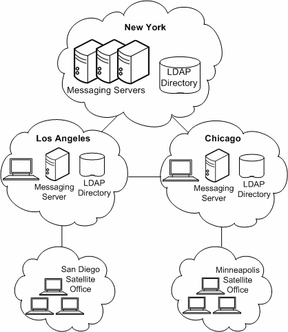
Description of ''Figure 5-7 Hybrid Topology for the Example Corporation''
Because New York has the highest message transaction rate of messages entering and leaving the system, it has the most number of messaging servers. The smaller offices, Los Angeles and Chicago, also support San Diego and Minneapolis. However, these satellite offices do not require their own messaging servers. Instead, Chicago and Los Angeles act as the central location for their services.
Step 3: Planning the Topology Elements
The final step in creating your messaging topology is to plan your topology elements in your actual deployment, as described in "Understanding Messaging Topology Elements". Figure 5-8 illustrates the topology elements in the Chicago and Minneapolis offices.
Figure 5-8 Topological Elements in the Example Messaging Deployment for Chicago and Minneapolis
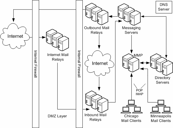
Description of ''Figure 5-8 Topological Elements in the Example Messaging Deployment for Chicago and Minneapolis''
Because 30 percent of the workforce is made up of third-party vendors and contractors, internal firewalls are used in addition to the external firewalls in the topology to restrict access to locations within the company. Internet MTAs are placed in the topology to route messages from the Internet and relay them across the firewall. MTAs are added to route incoming and outgoing messages. Separating incoming and outgoing messages helps to manage the high volume of message traffic. The MMP connects employees' POP and IMAP mail clients to their mailboxes in the Messaging Servers. By using an MMP, employees do not have to know their specific mail host when they log in, and administrators can seamlessly move employees' mailboxes to different mail server locations.
Creating a messaging topology enables you to account for the physical and logical placement of all the elements in your deployment. Doing so ensures minimal rework of your installation.
Using Logical Service Names
Design your deployment around the use of logical names for Messaging Server servers. You should use logical names even on a single-system deployment, to position it for ease of future growth and expansion.Using logical names does not impose any additional deployment setup costs other than populating your DNS.
You can think of these logical names as falling into two categories: those that affect end users, such as setting in email client programs; and those affecting back-end administration, such as inbound SMTP servers.
Table 5-1, Table 5-2, and Table 5-3 describe these logical entities.
Table 5-1 User Facing Logical Names
| Example | Description |
|---|---|
|
mail.example.com |
Name of the server from which end users collect their mail. |
|
imap.example.com |
Name of the IMAP server from which end users collect their mail. |
|
pop.example.com |
Name of the POP server from which the end users collect their mail. |
|
smtp.example.com |
Name of the SMTP server users set as outgoing mail server. |
Table 5-2 Maintenance Level Logical Names
| Example | Description |
|---|---|
|
relay-in.example.com |
Corresponds to a bank of inbound SMTP servers. |
|
relay-out.example.com |
Corresponds to a bank of outbound SMTP servers. |
|
mmp.example.com |
Corresponds to a bank of MMP servers. |
|
storeAA.example.com |
Back-end message store. Select a naming scheme to work with your topology, for example, calstoreAA.example.com through calstoreZZ.example.com. |
Table 5-3 Mapping of User Level to Maintenance Level Logical Names
| Maintenance Level | User Level |
|---|---|
|
relay-in.example.com |
Not applicable. |
|
relay-out.example.com |
smtp.example.com. |
|
mmp.example.com |
Any one or more of mmp.example.com, and imap.example.com. |
|
storeAA.example.com - storeZZ.example.com |
Not applicable, hidden from end users. |
|
calstore_aa.example.com - calstore_az.example.com |
Not applicable, hidden from end users. |
