5 General Purpose Input/Output
This chapter describes the General Purpose Input/Output (GPIO) functionality in the Oracle Java ME Embedded product. GPIO typically refers a generic pin on an embedded board whose behavior, including whether it is an input or output pin, can be programmed by the user at runtime.
GPIO pins are often lined up in rows. By design, they have no dedicated purpose, and are used by programmers for a wide variety of tasks. For example:
-
GPIO pins can be enabled or disabled.
-
GPIO pins can be configured to be input or output.
-
Input values are readable, often with a 1 representing a high voltage, and a 0 representing a low voltage.
-
Input GPIO pins can be used as "interrupt" lines, which allow a peripheral board connected via multiple pins to signal to the primary embedded board that it requires attention.
-
Output pin values are both readable and writable.
WARNING:
Be sure to observe manufacturer's specifications and warnings carefully. For example, with the Raspberry Pi board, the voltage value that represents a "high" value on an input pin may be 3.3 volts (+3.3V). However, other pins may output 5 volts (+5V). Be sure to check the manufacturer's specifications to ensure that you are not placing too much voltage on an input GPIO line, as the board may not have an overvoltage protection.
GPIO pins have much greater functionality than this, but it is important to start with the basics.
Setting a GPIO Output Pin
For this example, you will need the following hardware:
Table 5-1 Hardware for GPIO Example
| Hardware | Where to Obtain |
|---|---|
|
Raspberry Pi 512 MB Rev B, B+, or Raspberry Pi 2 |
Various third-party sellers |
|
Multimeter |
Various. Sinometer DT830B used in the example. |
Perhaps the simplest example of working with the GPIO functionality in the Oracle Java ME Embedded product is to set the high/low value of an arbitrary output pin and read its voltage with a multimeter. In this example, we set the value of GPIO pin 7 to alternate between high (3.3V) and low (0V) at intervals of 10 seconds and 5 seconds, respectively. The following example shows the source code.
import jdk.dio.UnavailablePeripheralException;
import jdk.dio.DeviceManager;
import jdk.dio.gpio.GPIOPin;
import java.io.IOException;
import java.util.logging.Level;
import java.util.logging.Logger;
import javax.microedition.midlet.MIDlet;

public class GPIOExample1 extends MIDlet {

    GPIOPin pin;

    public void startApp() {

        try {

            pin = (GPIOPin) DeviceManager.open(7);
            System.out.println("----------------------------------------");
            Thread.sleep(5000);

            for (int i = 0; i < 20; i++) {
                System.out.println("Setting pin to true...");
                pin.setValue(true);
                Thread.sleep(10000);
                System.out.println("Setting pin to false...");
                pin.setValue(false);
                Thread.sleep(5000);
                System.out.println("----------------------------------------");

            }

        } catch (IOException ex) {
            Logger.getLogger(GPIOExample1.class.getName()).
                log(Level.SEVERE, null, ex);
        } catch (InterruptedException ex) {
            Logger.getLogger(GPIOExample1.class.getName()).
                log(Level.SEVERE, null, ex);
        }
    }

    public void pauseApp() {
    }

    public void destroyApp(boolean unconditional) {

        try {
            pin.close();
        } catch (IOException ex) {
            Logger.getLogger(GPIOExample1.class.getName()).
                log(Level.SEVERE, null, ex);
        }

    }
}
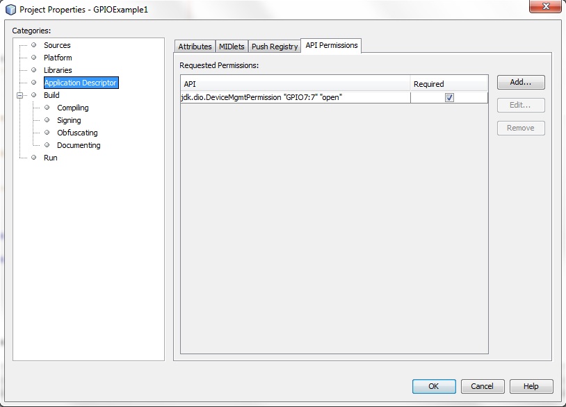
The following permissions must be added to the Application Descriptor of the IMlet so that it will execute without any security exceptions from the Oracle Java ME Embedded runtime.
Table 5-2 Permissions for GPIO Example
| Permission | Device | Operation |
|---|---|---|
|
|
|
|
Note that if you're using an IDE such as NetBeans as the development environment, you will need to access the project properties of the project and set API permissions under the application descriptor, as shown in Figure 5-1.
Figure 5-1 API Permissions in the Application Descriptor in NetBeans
Description of "Figure 5-1 API Permissions in the Application Descriptor in NetBeans"
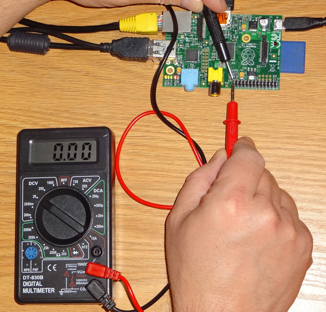
After running the application, set your multimeter to read DC voltage with a maximum of 20V, then connect one of the leads of the multimeter to GPIO 7, and the other to GND (ground). As the application is running, note that the voltage that is read by the multimeter will jump from its low value of around 0V after a call to pin.setValue(false) to its high value of around 3.3V after a call to pin.setValue(true). This is shown in Figure 5-2 and Figure 5-3.
WARNING:
Remember that the GPIO pin assignments on the Raspberry Pi do not match the pin numbers on the board. For example, GPIO 7 is not mapped to pin 7, but instead pin 26. See Appendix A (or the hardware-appropriate Getting Started Guide) for the pin assignments for the target boards of the Oracle Java ME Embedded software.
Figure 5-2 Raspberry Pi Pin 7 with Low (0V) Voltage
Description of "Figure 5-2 Raspberry Pi Pin 7 with Low (0V) Voltage"
Figure 5-3 Raspberry Pi Pin 7 with High (3.3V) Voltage
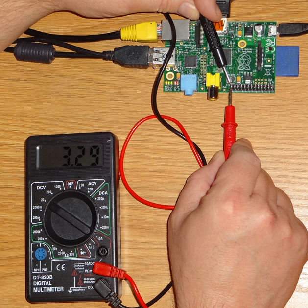
Description of "Figure 5-3 Raspberry Pi Pin 7 with High (3.3V) Voltage"
Working with a Breadboard
When prototyping circuits, it is often helpful to have a way of connecting wires without having to perform soldering. In some cases, if there are only a few connections, you can use jumper wires. However, when layout out more complex circuits, it's helpful to use a breadboard. A typical breadboard is shown in Figure 5-4.
A breadboard consists of a large number of holes, each of which are wired together on the bottom using a standardized pattern, such as the one shown in Figure 5-5. Note that the two columns on both the left and the right of the breadboard are wired vertically--these provide power (+) and ground (-) connections that can be tapped into to. The horizontal rows on either side of the center line, on the other hand, are used to create circuits. Circuits can be created using small wires with metal tips on each end that can "plug into" the holes.
Figure 5-5 Wiring Pattern for a Typical Breadboard

Description of "Figure 5-5 Wiring Pattern for a Typical Breadboard"
For the Raspberry Pi, we can connect the GPIO pins on the Pi to a breadboard using a device called a T-Cobbler Extension Board. This device attaches a ribbon cable to the GPIO pins, which in turn connects to the T-cobbler board. The T-cobbler board is then inserted into the top of the breadboard, as shown in Figure 5-6.
Figure 5-6 T-Cobbler Extension Board for the Raspberry Pi
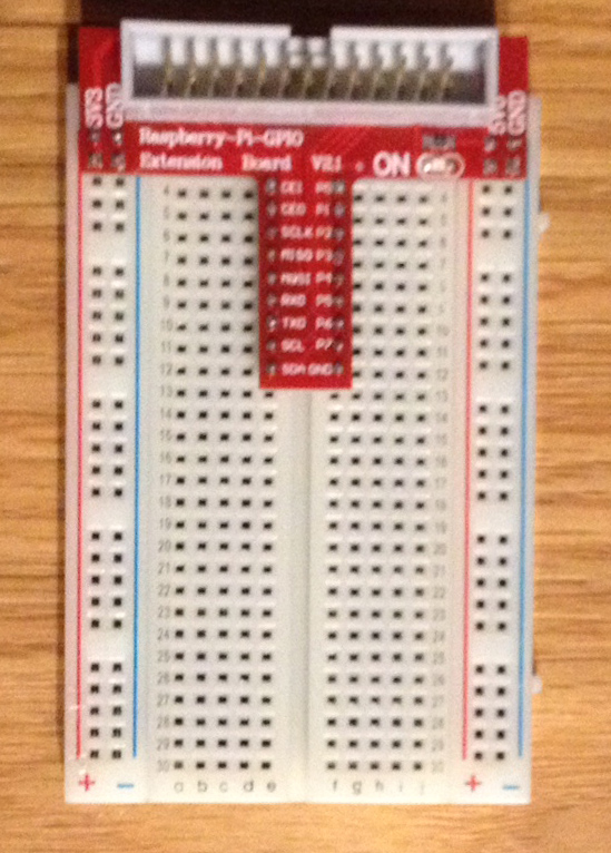
Description of "Figure 5-6 T-Cobbler Extension Board for the Raspberry Pi"
Once connected to the Pi, you can use any of the holes running along the red stripe on the left side of the breadboard to provide +3.3 volts (3V3), or any of the holes running along the red stripe on the right side of the breadboard to provide +5 volts (5V0). In addition, any of the holes running along the blue stripes on either side of the board connect to the ground (GND) on the Raspberry Pi.
The GPIO pins on the Raspberry Pi map to the pins on the T-cobbler (and hence the respective horizontal rows on the breadboard) as shown in Figure 5-3.
Table 5-3 Broadcom GPIO to T-Cobbler Conversion
| GPIO (Pi Pin Number) | Alternate Name |
|---|---|
|
2 (Pin 3) |
SDA |
|
3 (Pin 5) |
SCL |
|
4 (Pin 7) |
P7 |
|
7 (Pin 26) |
CE1 |
|
8 (Pin 24) |
CE0 |
|
9 (Pin 21) |
MISO |
|
10 (Pin 19) |
MOSI |
|
11 (Pin 23) |
SCLK |
|
14 (Pin 8) |
TXD |
|
15 (Pin 10) |
RXD |
|
18 (Pin 12) |
P1 |
|
22 (Pin 15) |
P3 |
|
23 (Pin 16) |
P4 |
|
24 (Pin 18) |
P5 |
|
25 (Pin 22) |
P6 |
|
27 (Pin 13) |
P2 |
Blinking an LED
We can use the code in the first example to create a small circuit on the breadboard that turns on an off a light-emitting diode (LED). For this example, you will need the following equipment.
Table 5-4 Equipment Needed for Blinking LED Example
| Hardware | Where to Obtain |
|---|---|
|
LED |
Any electronics store |
|
1000 ohm resistor |
Any electronics store |
|
T-Cobbler and Breadboard |
Adafruit |
|
Jumper Wires (Male to Male) |
Adafruit |
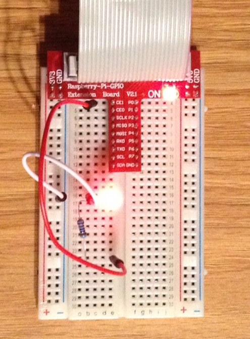
Use the breadboard to connect one end of a 1000-ohm resistor to a row that connects to GPIO7, which is marked on the T-Cobbler by CE1. Plug the other end of the 1000-ohm resistor into an unused row further down the breadboard. Then, run an LED from that row an adjacent row, and then connect that row to the ground (GND). The circuit should look similar to the schematic in Figure 5-7.
Figure 5-7 Schematic for Wiring an LED to GPIO 7
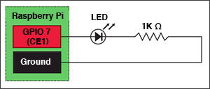
Description of "Figure 5-7 Schematic for Wiring an LED to GPIO 7"
When completed, you should have a prototype that looks like Figure 5-8. Run the first example again, and you should see the LED light blinking off an on whenever the setValue(true) call is made on the GPIOPin object.
Note:
Remember that an LED is a diode, which by definition only allows current to travel one way through it. If your LED does not light up when the voltage is applied, try flipping the connections so that the current travels the reverse direction through the diode.
Testing Output and Input Pins
Our next GPIO example will take the output voltage from one pin and redirect it back to an adjacent input pin, while creating a listener on the input pin that reacts accordingly. For this example, you will need the following hardware:
Table 5-5 Hardware for Example 1-1
| Hardware | Where to Obtain |
|---|---|
|
Raspberry Pi 512 MB Rev B |
Various third-party sellers |
|
Multimeter |
Various. Sinometer DT830B used in the example. |
Here, we use GPIO 8 and 11 on the Raspberry Pi due to their proximity to each other. These pins are right next to GPIO 7 and GND, which was used in the previous example. In the example below, we've added a listener to an input pin that will trigger whenever the input voltage changes in both directions (high-to-low and low-to-high).
import jdk.dio.UnavailablePeripheralException;
import jdk.dio.DeviceManager;
import jdk.dio.gpio.GPIOPin;
import jdk.dio.gpio.PinEvent;
import jdk.dio.gpio.PinListener;
import java.io.IOException;
import java.util.logging.Level;
import java.util.logging.Logger;
import javax.microedition.midlet.MIDlet;

public class GPIOExample2 extends MIDlet {

    GPIOPin pin8;
    GPIOPin pin11;

    public void startApp() {

        try {

            pin8 = (GPIOPin) DeviceManager.open(8);   //  Output pin by default
            pin11 = (GPIOPin) DeviceManager.open(11);  //  Input pin by default
            pin11.setInputListener(new MyPinListener());

            System.out.println("----------------------------------------");
            Thread.sleep(5000);

            for (int i = 0; i < 20; i++) {
                System.out.println("Setting pin 8 to true...");
                pin8.setValue(true);
                Thread.sleep(10000);
                System.out.println("Setting pin 8 to false...");
                pin8.setValue(false);
                Thread.sleep(5000);
                System.out.println("----------------------------------------");

            }

        } catch (IOException ex) {
            Logger.getLogger(GPIOExample2.class.getName()).
                log(Level.SEVERE, null, ex);
        } catch (InterruptedException ex) {
            Logger.getLogger(GPIOExample2.class.getName()).
                log(Level.SEVERE, null, ex);
        }
    }

    public void pauseApp() {
    }

    public void destroyApp(boolean unconditional) {

        try {
            pin8.close();
            pin11.close();
        } catch (IOException ex) {
            Logger.getLogger(GPIOExample2.class.getName()).
                log(Level.SEVERE, null, ex);
        }

    }

    class MyPinListener implements PinListener {

        @Override
        public void valueChanged(PinEvent event) {
            try {
                System.out.println("Pin listener for pin 11 has been called!");
                System.out.println("Pin 11 is now " + pin11.getValue());
            } catch (IOException ex) {
                Logger.getLogger(GPIOExample2.class.getName()).
                    log(Level.SEVERE, null, ex);
            }
        }

    }
}
Table 5-6 shows the permission that must be added to the Application Descriptor of the IMlet so that it will execute without any security exceptions from the Oracle Java ME Embedded runtime.
Table 5-6 Permissions for Example 1-2
| Permission | Device | Operation |
|---|---|---|
|
|
|
|
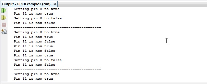
After running the application, either connect one of the leads of the multimeter to the GPIO 8 pin and the other to the GPIO 11 pin of the Raspberry Pi (or create a compatible circuit on a breadboard). Set your multimeter to read DCV with a maximum of 200 mV. As the application is running, note that the voltage that is read by the multimeter will jump from its low value to its high voltage, although the voltages will be much smaller than that from GPIO 7. Try disconnecting the lead from GPIO 11 momentarily and reconnecting it when GPIO 8 is high. The output of the program should reflect that the listener is called both when the lead is released, and when it is reconnected.
WARNING:
Remember that the GPIO pin assignments on the Raspberry Pi do not match the pin numbers on the board. For example, GPIO 8 is not mapped to pin 8, but instead pin 24. Likewise, GPIO 11 is mapped to pin 23. See Appendix A and Appendix B for the pin assignments for the target boards of the Oracle Java ME Embedded software.
The output of the application when running in NetBeans is shown in Figure 5-9.

