B Integrating with F5 BIG-IP LTM
This appendix provides instructions for using the F5 BIG-IP Local Traffic Manager (LTM) hardware load balancer to balance Coherence*Extend client connections. Instructions are also included to use the BIG-IP system to off load SSL processing.
The instructions are specific to using the BIG-IP Configuration Utility as it pertains to Coherence*Extend setup. Refer to the Help included with the utility for complete usage instructions. In addition, the instructions were created based on BIG-IP LTM 10.2.1 and may not be accurate for future releases of BIG-IP LTM.
This appendix includes the following sections:
B.1 Basic Concepts
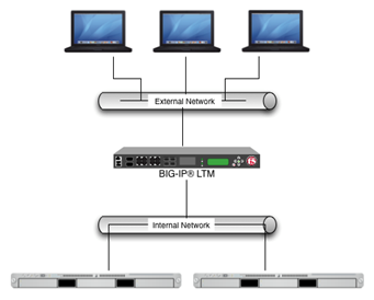
The F5 BIG-IP LTM is a hardware device that sits between one or more computers running Coherence*Extend clients (client tier) and one or more computers running Coherence*Extend proxy servers (proxy tier). The LTM spreads client connections across multiple clustered proxy servers using a broad range of techniques to secure, optimize, and load balance application traffic.
Figure B-1 shows a conceptual view of the BIG-IP system that is setup between external network clients and internal network servers.
Figure B-1 Conceptual View of F5 BIG-IP LTM
Description of "Figure B-1 Conceptual View of F5 BIG-IP LTM"
B.2 Creating Nodes
A node is a logical object on the BIG-IP system that identifies the IP address of a physical resource on the network. For Coherence*Extend, configure a node for each computer on the internal network that hosts one or more proxy servers.
To create a node:
-
Log into the BIG-IP Configuration Utility.
-
From the Main tab of the navigation pane, expand Local Traffic and click Nodes.
-
In the upper-right corner of the screen, click Create. The New Node screen displays.
-
For the Address setting, type the IP address of the node.
-
Specify, retain, or change each of the other settings.
-
Click Finished.
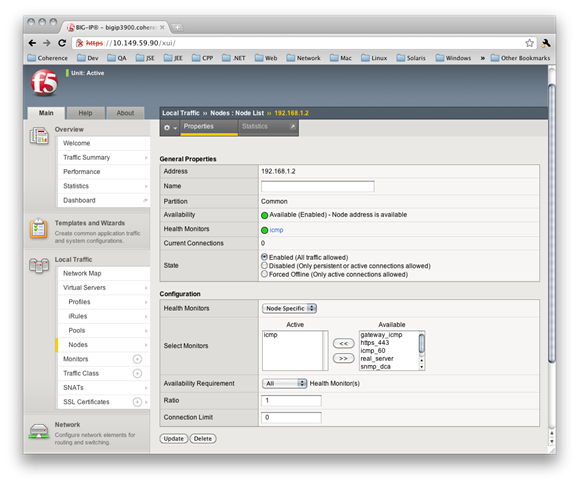
Figure B-2 shows an example node configuration.
B.3 Configuring a Load Balancing Pool
A load balancing pool is a group of logical devices, such as proxy servers, that receive and process traffic. Instead of sending client traffic to the destination IP address specified in the client request, the BIG-IP system sends the request to any of the servers that are members of that pool. This helps efficiently distribute the load on your server resources.
When you create a pool, you assign pool members to the pool. A pool member is a logical object that represents a server endpoint on the network. For Coherence*Extend, create a pool member for each proxy server JVM running on your proxy tier computers.
The specific pool member to which the BIG-IP system chooses to send the request is determined by the load balancing method that you have assigned to that pool. A load balancing method is an algorithm that the BIG-IP system uses to select a pool member for processing a request. For example, the default load balancing method is Round Robin, which causes the BIG-IP system to send each incoming request to the next available member of the pool, thereby distributing requests evenly across the servers in the pool.
The following topics are included in this section:
B.3.1 Creating a Load Balancing Pool
To create a load balancing pool:
-
Log into the BIG-IP Configuration Utility.
-
From the Main tab of the navigation pane, expand Local Traffic and click Pools. The Pools screen displays.
-
In the upper-right corner of the screen, click Create. The New Pool screen displays.
-
From the Configuration list, select Advanced.
-
For the Name setting, type a name for the pool.
-
Specify, retain, or change each of the other settings.
-
Click Finished.
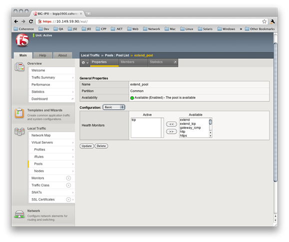
Figure B-3 demonstrates an example pool configuration.
B.3.2 Adding a Load Balancing Pool Member
To add pool members to load balancing pool:
-
From the Members tab, click the number shown. This lists the existing members of the pool.
-
In the right side of the screen, click Add. The New Pool Member screen displays.
-
In the Address box, select Node List and select an IP address.
-
In the Service Port box, type the port number on which the corresponding proxy server is listening.
-
Retain or change each of the other settings.
-
Click Finished.
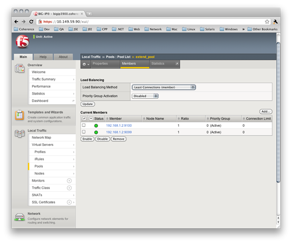
Figure B-4 shows an example pool configuration. It shows two proxy server pool members running on the previously created node and listening on ports 9099 and 9100, respectively. Additionally, the pool is configured to use a Least Connections load balancing policy.
B.4 Configuring a Virtual Server
A virtual server is a traffic-management object on the BIG-IP system that is represented by an IP address and port. Clients on an external network can send application traffic to a virtual server, which then directs the traffic according to your configuration instructions. The main purpose of a virtual server is often to balance traffic load across a pool of servers on an internal network. Virtual servers increase the availability of resources for processing client requests. For Coherence*Extend, you should configure a virtual server that directs traffic to the pool of proxy servers that you configured earlier.
To create a virtual server:
-
Log into the BIG-IP Configuration Utility.
-
From the Main tab of the navigation screen, expand Local Traffic and click Virtual Servers. The Virtual Servers screen displays.
-
From the upper right portion of the screen, click Create. The New Virtual Server screen displays.
-
In the Name box, type a name for the virtual server.
-
In the Destination box, assign an external IP address on the BIG-IP device and in the Service Port box, specify a listen port. This is the IP address and port to which Coherence*Extend clients connect.
-
Select the pool created earlier in the Default Pool drop-down box.
-
Retain or change each of the other settings.
-
Click Finished.
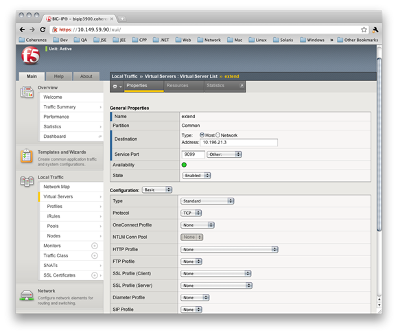
Figure B-5 shows an example virtual configuration that listens for TCP/IP connections on 10.196.21.3:9099.
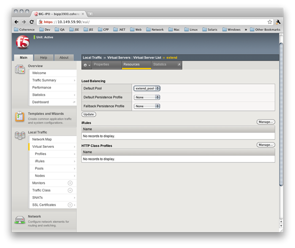
Additionally, this virtual server directs traffic to the configured pool as shown in Figure B-6.
Figure B-6 Example Virtual Server Using a Configured Pool
Description of "Figure B-6 Example Virtual Server Using a Configured Pool"
B.5 Configuring Coherence*Extend to Use BIG-IP LTM
Coherence*Extend must be configured to use a BIG-IP LTM virtual server. The configuration must be completed both on the cluster side and the client side cache configuration files.
To configure Coherence*Extend to use BIG-IP LTM:
-
Open the proxy server's cache configuration file.
-
Edit the proxy scheme definition and specify a client load balancing strategy by entering
clientwithin the<load-balancer>element. For example:<proxy-scheme> <service-name>ExtendTcpProxyService</service-name> <acceptor-config> <tcp-acceptor> <local-address> <address>192.168.1.2</address> <port>9099</port> </local-address> </tcp-acceptor> </acceptor-config> <load-balancer>client</load-balancer> <autostart>true</autostart> </proxy-scheme> -
Save and close the proxy server's cache configuration file. Repeat step 2 for additional proxy servers.
-
Open the client's cache configuration file.
-
In the
<remote-cache-scheme>element, list the IP address and port of the BIG-IP virtual server. See "Configuring a Virtual Server". In addition, specify a<heartbeat-interval>element within the<outgoing-message-handler>element. This causes the client to periodically send a heartbeat message over its TCP/IP connection at the configured time interval. This is required to prevent the BIG-IP device from disconnecting idle clients. For example:<remote-cache-scheme> <scheme-name>extend-direct</scheme-name> <service-name>ExtendTcpCacheService</service-name> <initiator-config> <tcp-initiator> <remote-addresses> <socket-address> <address>10.196.21.3</address> <port>9099</port> </socket-address> </remote-addresses> </tcp-initiator> <outgoing-message-handler> <heartbeat-interval>5s</heartbeat-interval> </outgoing-message-handler> </initiator-config> </remote-cache-scheme> -
Save and close the client's cache configuration file.
B.6 Using Advanced Health Monitoring
A health monitor helps ensure that a server is in an operational state and able to receive traffic. The BIG-IP system contains many different preconfigured health monitors that you can associate with pools, depending on the type of traffic you want to monitor.
For Coherence*Extend, you can use a TCP health monitor to monitor a pool of proxy servers. This type of monitor marks a proxy server up if the BIG-IP device can establish a TCP/IP connection with the proxy server. While this is a fairly decent indication that a proxy server is functional, it does not guarantee that the proxy server can actually process client traffic. For more detailed monitoring, BIG-IP enables you to create custom health monitors that send a Coherence*Extend ping request to a proxy server and validate that an appropriate response is returned. This ensures that the proxy server is up and able to process client traffic.
The following topics are included in this section:
B.6.1 Creating a Custom Health Monitor to Ping Coherence
To create a custom Coherence*Extend health monitor that sends a Coherence*Extend ping request to a proxy server to ensure that it is operational:
-
Log into the BIG-IP Configuration Utility.
-
From the Main tab of the navigation pane, expand Local Traffic and click Monitors. The Monitors screen displays.
-
In the upper-right corner of the screen, click Create. The New Monitor screen displays.
-
Enter a name for the monitor in the Name box.
-
Select TCP in the Type drop-down box.
-
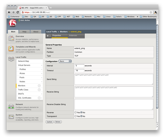
Enter the following in the Send String box:
\x07\x00\x03\x00\x00\x42\x00\x40
-
Enter the following in the Receive String box:
\x09\x00\x04\x02\x00\x42\x00\x03\x64\x40
-
Click Finished.
Figure B-7 shows an example custom Coherence*Extend health monitor configuration.
Figure B-7 Example Coherence*Extend Ping Health Monitor
Description of "Figure B-7 Example Coherence*Extend Ping Health Monitor"
The preceding approach only works with BIG-IP version 10.2.1 or higher. On older versions of BIG-IP, you must manually configure an external health monitor. To do so, create an executable shell script called extend_ping in the /usr/bin/monitors directory of the BIG-IP device with the following contents:
#! /bin/bash
###############################################################################
###  EXTERNAL MONITOR FOR COHERENCE*EXTEND
###   INPUTS:
###     $1    The IPV6 formatted IP address of the pool member to test
###     $2    The port number of the pool member to test
###     $3+   White space delimited parms as listed in the monitor "args"
###   OUTPUTS:
###     If null is returned, the member is "down"
###     If any string of one or more characters is returned, the member is "up"
###############################################################################

IP=${1:-"127.0.0.1"}
IP=${IP##*:} # This removes the leading ::ffff:
PORT=${2:-"80"}
TIMEOUT=${3:-1}
SLEEP=${4:-1}

PID_FILE="/var/run/extend_ping.$IP.$PORT.pid"
HEX_REQUEST="0700030000420040"
HEX_RESPONSE="09000402004200036440"

###
### Terminate existing process, if any
###
if [ -f $PID_FILE ]
then
   kill -9 `cat $PID_FILE` > /dev/null 2>&1
fi
echo "$$" > $PID_FILE

###
###  Ping the server and return a user friendly result
###
RESULT=`/bin/echo "$HEX_REQUEST" | /usr/bin/xxd -r -p | /usr/bin/nc -i \
    $SLEEP -w $TIMEOUT $IP $PORT | /usr/bin/xxd -p | /bin/grep \
    "$HEX_RESPONSE" 2> /dev/null`

if [ "$RESULT" != "" ] ; then
   /bin/echo "$IP:$PORT is \"UP\""
fi

rm -f $PID_FILE
To configure BIG-IP to use the extend_ping script:
-
From the Main tab of the navigation pane, expand Local Traffic and click Monitors. The Monitors screen displays.
-
In the upper-right corner of the screen, click Create. The New Monitor screen displays.
-
Enter a name for the monitor in the Name box.
-
Select External in the Type drop-down box.
-
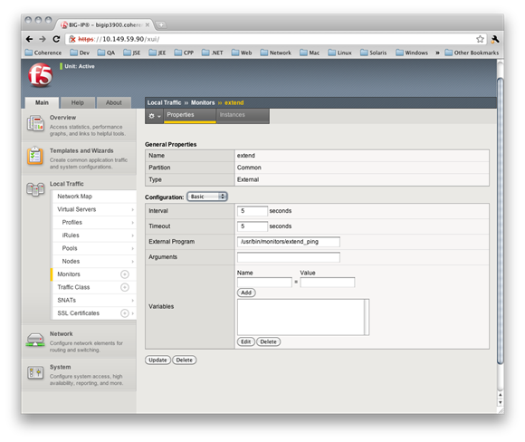
Enter the following in the External Program box:
/usr/bin/monitors/extend_ping
-
Click Finished.
Figure B-8 shows an example external Coherence*Extend health monitor configuration.
Figure B-8 Example Coherence*Extend Health Monitor Implemented in a Shell Script
Description of "Figure B-8 Example Coherence*Extend Health Monitor Implemented in a Shell Script"
B.6.2 Associating a Custom Health Monitor With a Load Balancing Pool
Custom health monitors must be associated with a load balancing pool. After creating a custom Coherence*Extend monitor, associate it with the Coherence*Extend load balancing pool.
To associate a custom health monitor with a load balancing pool:
-
Log into the BIG-IP Configuration Utility.
-
From the Main tab of the navigation pane, expand Local Traffic and click Pools. The Pools screen displays.
-
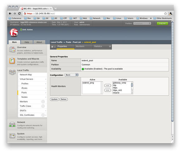
Click the name of your Coherence*Extend pool. The Pool screen displays.
-
Select the name of your custom Coherence*Extend health monitor in the Health Monitors box.
-
Click Update.
Figure B-9 shows a Coherence*Extend pool that uses a custom health monitor.
Figure B-9 Associating a Coherence*Extend Pool With a Custom Health Monitor
Description of "Figure B-9 Associating a Coherence*Extend Pool With a Custom Health Monitor"
B.7 Enabling SSL Offloading
Coherence*Extend can be configured to use SSL to secure communication between client and proxy server processes. However, this confidentially comes at a price. Specifically, enabling SSL dramatically increases CPU utilization in the proxy tier and increases the latency of each request. BIG-IP SSL Acceleration frees up proxy servers from the difficult task of encrypting and decrypting data secured for privacy reasons. CPU-intensive decryption is migrated onto a high-performance device designed to handle SSL transactions more efficiently. This approach is known as SSL offloading.
The following steps are required to enable SLL offloading and should be completed in the order presented:
-
Enable SSL in the Coherence*Extend client cache configuration file. See Securing Oracle Coherence for details on configuring an extend client to use SSL.
B.7.1 Import the Server's SSL Certificate and Key
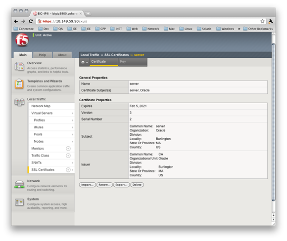
To import the server's SSL certificate and key to the BIG-IP system:
-
Log into the BIG-IP Configuration Utility.
-
From the Main tab of the navigation pane, expand Local Traffic and hover over SSL Certificates then select Import. The SSL Certificate screen displays.
-
From the Import Type drop-down box, select PKCS12.
-
Enter a name for the certificate in the Certificate Name box.
-
Click Choose File and browse to the server's PKCS12 file.
-
Enter the password for the PKCS12 file.
-
Click Import.
Figure B-10 shows an example server SSL certificate configuration:
Figure B-10 Example SSL Certificate Configuration in BIG-IP System
Description of "Figure B-10 Example SSL Certificate Configuration in BIG-IP System"
B.7.2 Create the Client SSL Profile
To create the client SSL profile:
-
From the Main tab of the navigation pane, expand Local Traffic and hover over Profiles then SSL and select Client. The Client SSL Profiles screen displays
-
In the upper-right corner of the screen, click Create. The New Client SSL profile screen displays.
-
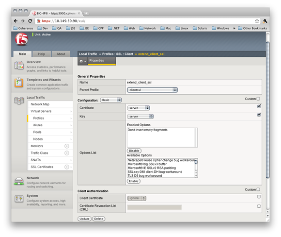
Enter a name for the client SSL profile in the Name box.
-
Click the Custom check box on the right.
-
Select the name of the server certificate that you imported earlier in both the Certificate and Key drop-down boxes.
-
Click Finished.
Figure B-11 shows an example client SSL profile configuration:
Figure B-11 Example SSL Profile Configuration
Description of "Figure B-11 Example SSL Profile Configuration"
B.7.3 Associate the Client SSL Profile
To modify the Coherence*Extend virtual server configuration to use the client SSL profile:
-
From the Main tab of the navigation screen, expand Local Traffic and click Virtual Servers. The Virtual Servers screen displays.
-
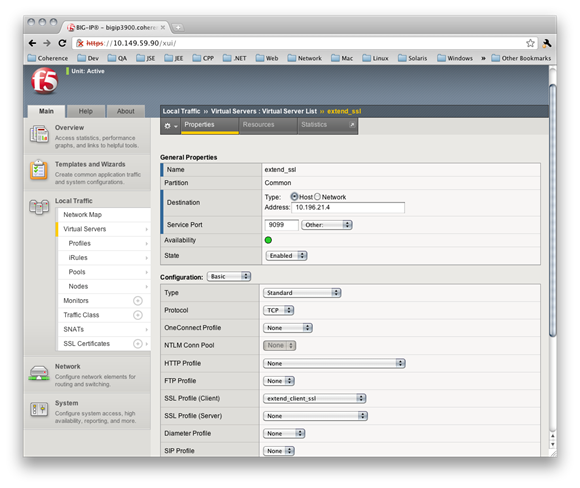
Click the name of the virtual server.
-
Select the name of the client SSL profile in the SSL Profile (Client) drop-down box.
-
Click Update.
Figure B-12 shows an example virtual server configuration that uses a client SSL profile:
Figure B-12 Example Virtual Server Configuration That Includes a Client SSL Profile
Description of "Figure B-12 Example Virtual Server Configuration That Includes a Client SSL Profile"
