5 Modeling Data Services Relationships
This chapter describes modeling data services relationships.
This chapter contains the following sections:
5.1 Relationship Between Data Services and Models
In large enterprises modeling is — or at least should be — an early task in developing a data services layer. By starting with a graphical representation of data resources it is easier to view data resources globally, leveraging existing information in interesting and useful ways. It is also easy to see opportunities for creating additional business logic in the form of logical services.
Model diagrams are quite flexible; they can be based on existing data services (and corresponding underlying data sources), planned data services, or a combination. You can also create and modify data services and data service XML types directly from the model.
Relationships can be surfaced through the Relationship Modeler in several ways:
-
Automatically. By dragging two or more relational-based data services into a model diagram simultaneously. In such cases primary/foreign key relationships -- already available in the respective data service -- appear.
-
Graphically. Through gestures you make in your model diagram or through the right-click menu*.*
-
Programmatically. Through a data service Source editor.
Relationship functions allows data associated with one data service (such as Customer) to serve as a complex parameter for a related data service (such as Orders). Models can represent any combination of logical and physical data services.
A visual representation of a relationship between two data services can convey a considerable amount of information:
-
Cardinality. Is the relationship one-to-zero (customers and promotional offers), one-to-one (customer and primary email), one-to-many (customers and orders), or many-to-many (customer orders and ordered items)?
-
Direction. Arrows indicate possible navigation paths. Is there an originating entity associated with a subordinate entity (such as orders and order items) or is the relationship bidirectional (such as customers and orders)?
-
Roles. A name matching the name of the adjacent data services navigation function (see below). Does the assigned relationship name capture the purpose of the navigation function it represents?
Many data service-related operations can be performed from the relationship modeler including:
-
Modeling a high-level, visual view of data resources
-
Viewing and adding to the relationships between data services
-
Accessing or creating a data service
-
Add operations to a data service
-
Change the XML type (schema) associated with a data service
Navigation functions are visible as properties of each data service in the binary relationship. They can be fully inspected in the Source editor for each data service. Navigation functions also appear as mouse-over text over each endpoint of the relationship line.
By default, types shown in model diagrams are XML schema types, but you can change this to display native data source types in the case of physical data services.
Tip:
For more information on data service modeling concepts see Modeling and a Service-Oriented Architecture in the ODSI Concepts Guide.
5.2 How to...
This section provides procedures for modeling in Oracle Data Service Integrator.
This section describes the following sections:
5.2.1 Create Your First Data Services Model
This section provides a basic overview of modeling in Oracle Data Service Integrator and a tutorial.
This section describes the following sections:
5.2.1.1 Introduction
Using Oracle Data Service Integrator, you can create and maintain models of your enterprise data services. A model diagram is a graphical representation of a data model supported by Oracle Data Service Integrator.
Through data models you can:
-
Model a high-level, visual view of data resources.
-
View and extend relationships between data services.
-
Access and create a data service.
-
Add operations to a data service.
-
Change the XML type (schema) associated with a data service.
In model diagrams, a relationship can be created by the gesture of drawing a line from one data service to another. In some cases (such as relational data services) relationships and the lines representing the relationship can be automatically inferred. In other cases, you need to create the relationship.
A visual representation of a relationship between two data services conveys a considerable amount of information:
-
Cardinality. Is the relationship one-to-zero (customers and promotional offers), one-to-one (customer and primary email), one-to-many (customers and orders), or many-to-many (customer orders and ordered items)?
-
Direction. Arrows indicate possible navigation paths. Is there an originating entity associated with a subordinate entity (such as orders and order items) or is the relationship bidirectional (such as customers and orders)?
-
Roles. A name matching the name of the adjacent data services navigation function (see below). Does the assigned relationship name capture the purpose of the navigation function it represents?
Navigation functions are visible as properties of each data service in a binary relationship. Navigation functions also appear as mouse-over text over each endpoint of the relationship line.
Types shown in model diagrams are XML schema types.
Figure 5-1 Model Diagram of Physical Data Services
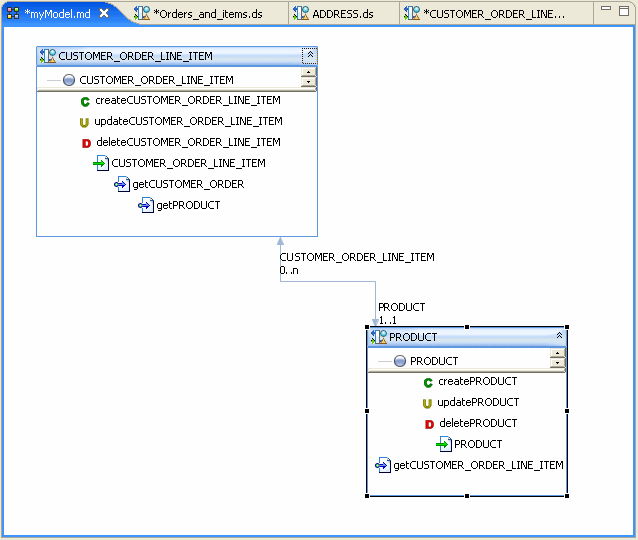
Description of "Figure 5-1 Model Diagram of Physical Data Services"
5.2.1.2 Building a Simple Data Service Relationship Model
You can create a sample data service relationship model by selecting a dataspace project and choosing:
File > New > Relationship Modeler
You can locate your model diagram anywhere in your project. Any legal filename can be used.
5.2.1.2.1 About the Data Services
This example assumes that you are using the Oracle Data Service Integrator RTLApp as a data source.
The physical data services used in this sample are:
-
CUSTOMER
-
CUSTOMER_ORDER
-
CUSTOMER_ORDER_LINE_ITEM
5.2.1.2.2 Adding Data Services to the Modeler
You can add data services to your model using simple drag-and-drop from the Project Explorer. In the Project Explorer you can multi-select data services using either:
-
Shift-click (contiguous services) or
-
Control-click (individual services)
If you drag a set of data services into a model diagram, existing relationships to other data services in the model will be shown.
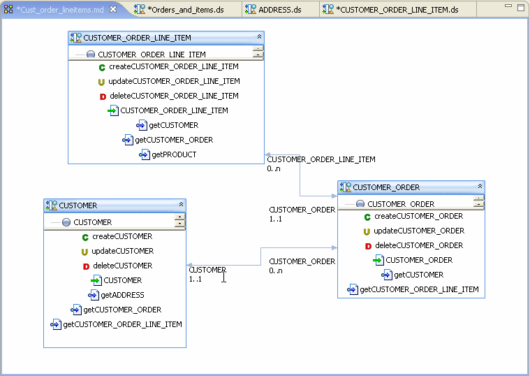
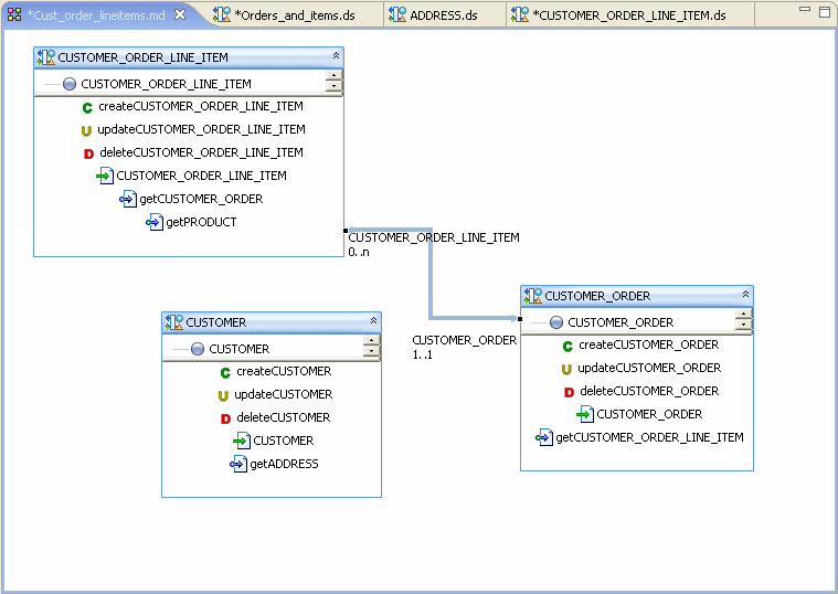
Figure 5-2 Populating the Relationship Modeler
Description of "Figure 5-2 Populating the Relationship Modeler"
Since the data services in this example are representations of relational sources, a several bidirectional relationships between CUSTOMER_ORDER and CUSTOMER_ORDER_LINE_ITEMS were inferred:
-
The role named CUSTOMER_ORDER has a 1-to-1 relationship with CUSTOMER_ORDER_LINE_ITEM, meaning that a line item can only belong to one order.
-
The role named CUSTOMER_ORDER_LINE_ITEM has a 0-to-n relationship with CUSTOMER_ORDER, meaning that there can be many line items associated with an order.
5.2.1.2.3 Creating an Additional Relationship
A next step could be to create a relationship between CUSTOMER and CUSTOMER_ORDER.
-
Right-click on CUSTOMER_ORDER node.
-
Select Create Relationship to another data service.
-
Select CUSTOMER as the target data service.
-
Click OK.
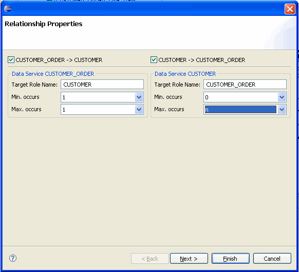
The Relationship Properties wizard appears.
5.2.1.3 Setting Relationship Properties
Relationship properties can be uni- or bi-directional.
Table 5-1 Relationship Properties Dialog Options
| Option | Action | Comment/Reference |
|---|---|---|
|
Set directionality |
Select the directions to be supported in the relationship. The example is bidirectional so the default checked condition for the following relationships need not be changed:
|
Creating relationships in a model automatically creates relationship functions between data services. Bi-directional settings mean that ” |
|
Target Role Name |
Enter the name of the role function. In the example, default names can be used:
|
By default the name will be based on the name of the related data service. It can be changed to any unique and legal name in your dataspace project. |
|
Set maximum and minimum occurrences |
Enter cardinality settings for the respective function. For the example the following settings are used:
|
The minimum and maximum occurrence settings definite the nature of the relationship between the two services. |
Click Next.
5.2.1.4 Configuring Navigation Functions
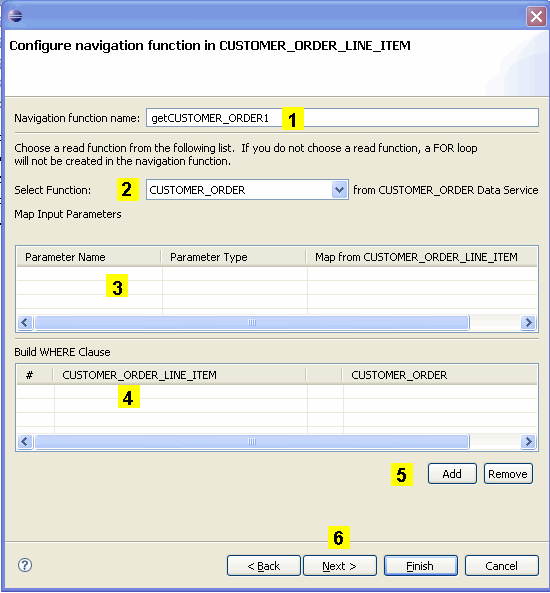
Each navigation function (one or two) being created also needs to be configured. Configuration includes:
-
Setting a name for the navigation function
-
Selecting a function from the newly related data service.
-
Mapping input parameters
-
Building a WHERE clause
Figure 5-4 Configuring a Navigation Function
Description of "Figure 5-4 Configuring a Navigation Function"
Table 5-2 Specifying Relationship Wizard Function Name, Parameters, and Where Clauses
| Element | Purpose |
|---|---|
|
Navigation function name |
By default, the navigation function name is the name of the target data service with ”get” prepended, as in ”getCustomer.” If a function of that name exists, numbers will be appended to the function name as in getCustomer1. Note: When you invoke the Relationship wizard through a model diagram the opposite data service is determined by the gesture of drawing a line from one data service to another. In such cases the option of selecting a navigation function name is not present. |
|
Related data service function |
By default, the root function in the target data service is selected. However, you can select any available read function in the target data service. |
|
Map input parameters |
If the related function has input parameters, the name and type of the available parameters appear. You can then use a pull-down menu to select an element from the target data service to map as the input parameter. |
|
Build WHERE clause |
Where clauses can be added to the function using pull-down menus that allow you to select join elements from each side of the relationship. |
|
Add or Remove |
Allows you to add additional where clauses or delete an identified where clause. |
|
Next |
When the relationship between data services is bidirectional clicking Next changes the focus to the second data service, where you can identify a navigation function name, parameters, and add where clauses for the second side of the relationship. |
5.2.2 Work with Large Models
How To Work with Large Model Diagrams
Model diagrams can hold any number of data services. The only limitation is that each data service must reside in the same dataspace.
Some tools are available in cases where very large models have been created.
5.2.2.1 Search
You can locate any data services in your model diagram.
-
Right-click in the white space (not on a data service representation) and select Find Data Service.
-
Type in the name of your data service using standard search options available in the dialog.
A dialog will appear containing a dropdown list of matching data services. The data service you select will be appear.
5.2.3 Generate a Relationship Modeler Report
Generating Reports on Your Models
Both summary and detailed reports are available from the currently selected relationship model.
To create a report:
-
Right-click in any blank space in your model diagram.
-
Select:
Generated Report > Detailed or Generate Report > Summary
-
Select a filename and location.
-
Click Finish.
Table 5-3 Summary and Detailed Report Categories Compared
| Type | Description |
|---|---|
|
Summary Report |
Provides general information related the model including:
|
|
Detailed Report |
A detailed model report contains all summary information listed above and, for each relationship between data services, the following additional information:
|
When you choose the Create a Model Report right-click option you are asked to select a name for the HTML document that is generated. By default, the name of the summary report is:
<model_name>_md_summary.html
and the name of the detail report is:
<model_name>_md_detail.html
You can save the report to any location in your application, including to a new folder.
5.3 Reference
This section describes the following sections:
5.3.1 Relationship Modeler Options
This section describes some of the common operations you will use when working with the relationship modeler.
5.3.1.1 Model Right-click Menu Options
You can edit your model using a combination of right-click menu options and the model Property Editor. Table 5-4 and Table 5-5 describe right-click options based on the functional area of the model diagram that is in scope.
Table 5-4 Data Model: Notable Data Model Options
| Command | Meaning |
|---|---|
|
New Data Service |
Allows you to create a new data service. After selecting a name and physical location for the data service, the service is created and placed on the diagram. |
|
Find Data Service |
Locates a data service within your model. |
|
Select Router Type |
Adjusts visual presentation of relationship lines based on the Manhattan model or shortest-path model. |
|
Generate Report |
Creates either a Summary or Detail report in an Eclipse HTML-based page. The report describes data services in your model, their bilateral relationships, and a description of each data service. |
Table 5-5 Data Service: Notable Data Model Options
| Command | Meaning |
|---|---|
|
Open |
Dialog allows you to select from a list of data services in the model diagram. As with drawing a line between two data services, this option brings up the Relationship wizard. (See Using the Relationship Wizard to Create Navigation Functions). |
|
Create Relationship to Another Data Service |
The Add Related command is available when one or several data services are selected in the model. Add Related lists data services that contain navigation functions referencing your currently selected data source. Click on the service you want to add and then repeat the process to add other available related services, if any. |
|
Add Related Data Service |
Adjusts visual presentation of relationship lines based on the Manhattan model or shortest-path model. |
|
Remove from Diagram |
Removes the selected data service from the model diagram. Alternatively, use the Delete key. Note: This operation does not affect the underlying data service. |
|
Refactor |
Provides for either safe delete or renaming of the currently selected data service. This is comparable to operations available for a data service from the Overview tab. |
|
Associate XML Type |
Provides a dialog where a different schema ( Note: Changing a schema type for a data service can affect its functions as well as its relationships to other data services. |
|
Manage Key... |
Opens the Manage Key dialog box, allowing for modification of the key associated with the current data service. |
|
Delete Key... |
Deletes any key associated with the current data service. |
|
Add Operation |
Adds an operation (function or procedure) to the currently selected data service. |
|
Show/Hide Native XML Types |
Optionally displays/hides native types for elements representing physical objects associated with simple data types. Example: |
|
Show Function Signatures |
Displays/hides full read function signatures such as: |
Tip:
Relationship lines connecting data services can be deleted by first selecting the line, then pressing Delete.
5.3.2 Model Diagram Rules
Rules Governing Model Diagrams
Model diagrams follow a set of rules:
-
Each entity in the model has a title which is the local name of the data service (the fully-qualified name is visible as a mouse-over).
-
Associated Read functions can be displayed, with or without signatures.
-
Model diagrams do not ”own” data services, but simply reference them. Multiple models can, without limit, contain representations of the same data service or relationships between data services.
-
Models are not nested. That is, a model diagram cannot reference another.
-
Multiple models can be defined and located anywhere in your project.
-
Changes made to a model diagram can be reversed using the Edit Undo command. However it is important to keep in mind that changes to any underlying files such as schemas (XML types) or data services made through the model will not be undone. Instead, edit the data service directly or close and reopen your application before saving your changes.
Note:
Changes to a model diagram that affect data services such as when a new relationship is created are only made permanent in Eclipse for WebLogic after you do a File > Save All.
5.3.3 Notable Relationship Modeler Properties
Properties both reflect and define relationships created in the model diagram.
Table 5-6 Notable Data Modeling Properties
| Scope | Property | Settings | Comments |
|---|---|---|---|
|
Data Service |
Properties described in Managing Your Data Service. |
||
|
Relationships |
Nodes |
Read only |
Shows names of the related data services and their respective roles. Roles are assigned as source data service and target data service, but these assignments are arbitrary in the case of bidirectional relationships. |
|
Source and Target Cardinality |
Drop down |
Value can be 0-to-1, 0-to-many, 1-to-1, 1-to-many, and many-to-many. |
|
|
Operations |
Properties described in Managing Your Data Service. |
5.3.4 Relationship Models in Source View
Generated Relationship Declarations in Source View
An example of a navigation function in the underlying source is:
(::pragma function <f:function xmlns:f="urn:annotations.ld.oracle.com"
kind="navigate" roleName="ADDRESS"/>::-)
This specifies a relationship to the Address data service from the Customer data service.
Data services also contain declarations describing the nature of the relationship; this information is the source for the role names and cardinality values that appear in your model diagram.
For example, the data service Address contains the following relationship declarations:
<relationshipTarget roleName="CUSTOMER" roleNumber="1"
XDS="ld:DataServices/CustomerDB/CUSTOMER.ds" opposite="ADDRESS"/>
For each data service, a relationship is created which identifies its role name, cardinality, opposite data service, and a unique (to the data service) role number.
In the above example, a navigation function is automatically created that retrieves customer information based on the customerID.
In the case of the relationship between Customer and Address, the relationship is 0-to-n for the Address role (it can make and appearance any number of times or not at all) based on CustomerID being a foreign key in Address and a primary key in the Customer data service (and the underlying relational data sources respectively).
Since the relationships are bilateral, Customer's opposite is Address while Address's opposite is Customer.
If your data model is composed of both physical and logical data services, you should keep in mind that a metadata update on any underlying physical data services will remove any relationships you have created involving those data services.
