Release 1 (9.0.1)
Part Number A88890-02
Home |
Book List |
Contents |
Index | Master Index | Feedback |
| Oracle9i Application Developer's Guide - Advanced Queuing Release 1 (9.0.1) Part Number A88890-02 |
|
![]()
![]()
This manual uses the Unified Modeling Language (UML) to present use case diagrams as a way of explaining technology. A brief explanation of use case diagrams and UML notation follows.
| Graphic Element | Description |
|---|---|
 Text description of the illustration qapumla.gif |
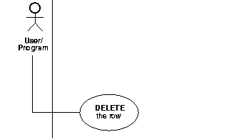
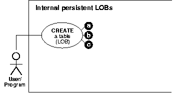
In a use case diagram, each primary use case is instigated by an actor (stickman), which can be a human user, an application, or a subprogram. The actor is connected to the primary use case, which is depicted as an oval (bubble) enclosing the use case action. The totality of primary use cases is described in a use case model diagram. |
 Text description of the illustration uml002.gif |
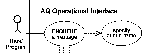
Primary use cases may require other operations to complete them. In this diagram fragment is one of the suboperations, or secondary use cases, needed to complete The downward lines from the primary use case lead to the other required operations (not shown). |
 Text description of the illustration uml003.gif |
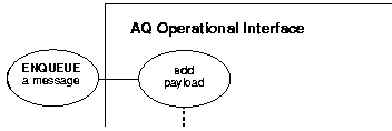
A secondary use case with a drop shadow expands into its own use case diagram, thus making it easier to: In this example are all expanded in separate use case diagrams. In the online versions of these diagrams, these are clickable areas that link to the related operation. |
 Text description of the illustration uml004.gif |
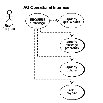
This diagram fragment shows the expanded use case diagram. While the standard diagram has the actor as the initiator, here the use case itself is the point of departure for the suboperation. In this example, the expanded view of represents a constituent operation of |
 Text description of the illustration uml005.gif |
The a, b, c convention shows that there are three ways to create a table containing LOBs. |
 Text description of the illustration uml006.gif |
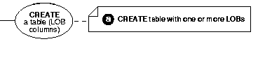
This fragment shows one of the uses of a note box, here presenting one of the three ways to create a table containing LOBs. |
Graphic Element
 Text description of the illustration uml007.gif |
|
Description
This drawing shows other uses of note boxes:
|
| Graphic Element | Description |
 Text description of the illustration uml008.gif |
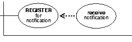
The dotted arrow in the use case diagram indicates dependency. In this example requires that you first
Put another way: you should not execute the The target of the arrow shows the operation that must be performed first. |
 Text description of the illustration uml009.gif
|
Use cases and their suboperations can be linked in complex relationships. In this example of a callback, you must first in order to later |
|
Graphic Element
Text description of the illustration uml007.gif |
|
Description
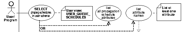
In this case the branching paths of an OR condition are shown. In invoking the view, you can choose to list all the attributes or view one or more attributes. The grayed arrow indicates that you can stipulate which attributes you want to view. |
Graphic Element
 Text description of the illustration uml011.gif |
|
Description
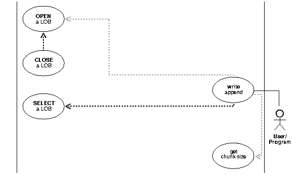
The black dashed line and arrow indicate that the targeted operation is required. The gray dashed line and arrow indicate that the targeted operation is optional. In this example, executing
on a You may optionally choose to
Note that if you do |
Graphic Element
 Text description of the illustration qapuml12.gif |
|
Description
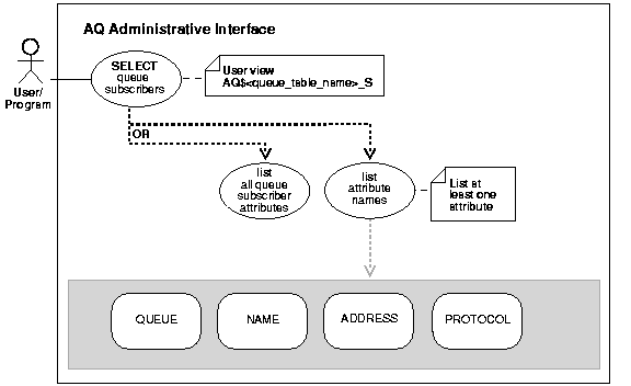
The previous notes have discussed use case diagrams. Here we introduce the basic application of a state diagram, which we use to present the attributes of view. Attributes of a view have only two states--visible or invisible. We are not interested in showing the permutations of state, but in showing what you can make visible in invoking a view. Accordingly, we have extended the UML to join a partial state diagram onto a use case diagram to show the totality of attributes, and thereby all the substates of the view that you can see. We have demarcated the use case from the view state by coloring the background gray. In this example, the view allows you to query queue subscribers. You can stipulate one attribute, some combination of the four attributes, or all four attributes. |
| Graphic Element | Description |
 Text description of the illustration uml013.gif |
Use case model diagrams summarize all the use cases in a particular domain, such as |
|
Text description of the illustration uml014.gif |
This marker indicates that the diagram is continued. |
The online (HTML and PDF) versions of these diagrams include active areas that have blue perimeters or look like buttons. You can use these links to traverse the following relationships:
The following examples illustrate these relationships.
| Graphic Element | Description |
 Text description of the illustration uml015.gif |
Use Case Model Diagrams, which summarize all the use cases in a particular domain, have active areas that link to the individual use cases. |
 Text description of the illustration uml010.gif |
Buttons in the individual Use Case Diagrams lead back to the Use Case Model Diagram |
Graphic Element
Text description of the illustration qapuml17.gif |
|
Description
This Use Case Diagram combines a number of the elements:
|
Graphic Element
Text description of the illustration qapuml18.gif |
|
Description
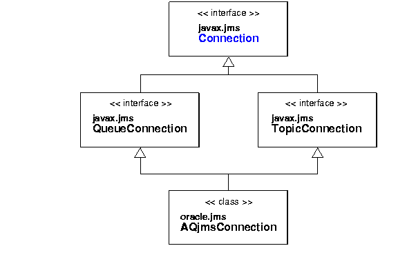
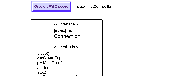
This class diagram has links to the individual class diagrams that form its components. This reduced view of the classes shows: |
Graphic Element
Text description of the illustration qapuml19.gif |
|
Description
The expanded view of the class diagram:
|
|
|
 Copyright © 1996-2001, Oracle Corporation. All Rights Reserved. |
|