|
Oracle® Application Server Adapter for Siebel User's Guide
10g Release 2 (10.1.2) Part No. B14062-01 |
|
 Previous |
 Next |
|
Oracle® Application Server Adapter for Siebel User's Guide
10g Release 2 (10.1.2) Part No. B14062-01 |
|
 Previous |
 Next |
This chapter provides the information you require to create schemas for Siebel Business Objects.
This chapter discusses the following topics:
Prerequisites
Before starting Application Explorer and using the OracleAS Adapter for Siebel, you must create \endorsed directories under your OracleAS_home directory and place a copy of the xalan.jar file in those directories.
Navigate to the OracleAS_home\j2ee\home\connectors\jca-app-adapter\jca-app-adapter directory and copy the xalan.jar file.
Create an \endorsed subdirectory in the following two directories:
OracleAS_home\jre\1.4.2\lib\
OracleAS_home\jdk\jre\1.4.2\lib\
Place a copy of the xalan.jar file into the new subdirectories.
When you are done, ensure that you have the xalan.jar file in the following two directories:
OracleAS_home\jre\1.4.2\lib\endorsed
OracleAS_home\jdk\jre\1.4.2\lib\endorsed
Launching Application Explorer
The server must be started where Application Explorer is deployed.
To start Application Explorer:
Ensure the server is started where Application Explorer is deployed.
On Windows, invoke iaexplorer.exe, found under OracleAS_home\adapters\application\tools or on UNIX, invoke the iwae script, iwae.sh, found under OracleAS_home/adapters/application/tools.
Application Explorer opens. You are ready to define new targets to your Enterprise Information System (EIS).
Before a repository project can be created, you must configure OracleAS Adapter Business Services Engine (BSE). You need not configure the OracleAS Adapter JCA because the ra.xml file is configured automatically during installation.
After the OracleAS Adapter Business Services Engine (BSE) is deployed to Oracle Application Server, you can configure it through the BSE configuration page.
To configure BSE:
Open the following page in your browser:
http://hostname:port/bse
Is the hostname of the Oracle Application Server.
For example,
http://localhost:7777/bse
|
Note: The first time you access this page, it may take time to load. |
When prompted, log on.
When first installed, the user ID and the password are:
User name: admin
Password: admin
The BSE configuration page opens.
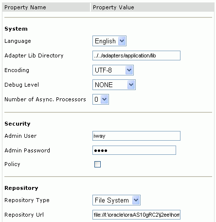
Ensure the Adapter Lib Directory parameter specifies the path to the lib directory, for example:
OracleAS_home\adapters\application\lib
After you specify the path, adapters in the lib directory are available to BSE.
|
Note: The Repository URL field specifies where the file system repository is located. To use a database repository, you must enter the repository connection information. For the initial verification, use a file system repository. See "Configuring an Oracle Repository" for information on switching to a database repository. |
Click Save.
To configure Business Services (BSE) system settings:
Open the BSE configuration page by entering the following URL:
http://hostname:port/ibse/IBSEConfig
|
Note: The server to which BSE is deployed must be running. |
The BSE settings window opens.
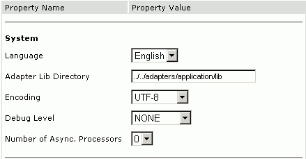
Configure the system settings by providing information for the parameters according to the following table.
The following image illustrates the Security pane of the window.

Configure the security settings by providing information for the parameters according to the following table.
| Parameter | Description |
|---|---|
| Admin User | Provide an BSE administrator ID. |
| Admin Password | Type the password associated with the BSE administrator ID. |
| Policy | Select the check box to enable policy security. |
The following image illustrates the Repository pane of the window.
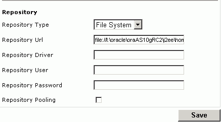
Configure the repository settings by providing information for the parameters according to the following table.
BSE requires a repository to store transactions and metadata required for the delivery of Web services.
See "Configuring a File System Repository" and "Configuring an Oracle Repository" for more information.
Configuring a File System Repository
If you do not have access to a database for the repository, you can store repository information in an XML file on your local machine. However, a file system repository is less secure and efficient than a database repository. When BSE is first installed, it is automatically configured to use a file system repository.
The default location for the repository on Windows is:
OracleAS_home\j2ee\OC4J_CONTAINER\applications\ws-app-adapter \ibse\ibserepo.xml
On other platforms, use the corresponding location.
If you are using a file system repository, you are not required to configure any additional BSE components.
Configuring an Oracle Repository
To configure an Oracle repository:
Contact your database administrator to obtain an Oracle user ID and password to create the BSE repository.
This user ID should have rights to create and modify tables as well as the ability to create and execute stored procedures.
Open a command prompt and navigate to the setup directory. Its default location on Windows is:
OracleAS_home\adapters\application\etc\setup
For other platforms, see the corresponding location.
This directory contains SQL to create the repository tables in the following file:
iwse.ora
|
Note: If Oracle is not on the same machine as the Oracle Application Server, copy the iwse.ora file to the Oracle machine. Then, from a command prompt on the Oracle machine, navigate to the directory containing the iwse.ora file. |
Before you use Application Explorer with the OracleAS Adapter for Siebel, you must create a repository project. You can create two kinds of repository projects, Web services and JCA, depending on the container to which the adapter is deployed. At design time, the repository is used to store metadata created when using Application Explorer to configure adapter connections, browse EIS objects, configure services, and configure listeners to listen for EIS events. The information in the repository is also referenced at runtime.
A default JCA repository is created for the default ManagedConnectionFactory. The name of this project is jca_sample.
Web services and the OracleAS Adapter Business Services Engine (BSE) refer to the same type of deployment. See "Adapter Features" for more information.
To create a Web service project for BSE using Application Explorer, you must first define a new configuration.
Defining a New Configuration for BSE
To create a new repository project for BSE:
Right-click Configurations and select New.
Enter a name for the new configuration (for example, SampleConfig) and click OK.
The following opens.
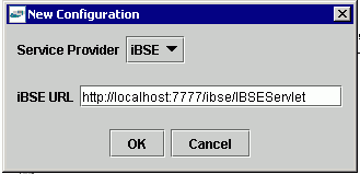
In the BSE URL field, accept the default URL or replace it with a different URL with the following format:
http://hostname:port/ibse/IBSEServlet
Is the machine where your application server resides.
Is the port number where the application server is listening.
Click OK.
A node representing the new configuration appears beneath the root Configurations node.

The Web service repository project file is stored in OracleAS_home\j2ee\home\applications\ws-app-adapter\ibse.
To create a repository project for the OracleAS Adapter JCA using Application Explorer, you must first define a new configuration.
Defining a New Configuration for JCA
To define a new configuration for JCA:
Right-click Configurations and select New.

Description of the illustration selectnewconfig.gif
The New Configuration dialog box opens.
Enter a name for the new configuration (for example, SampleConfig) and click OK.
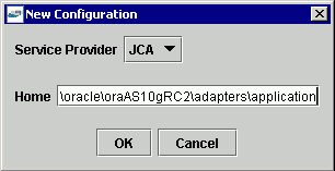
In the Home field, enter a path to your JCA configuration directory where the repository, schemas, and other information is stored, for example:
OracleAS_home\adapters\application
Click OK.
A node representing the new configuration appears beneath the root Configurations node.

The OracleAS Adapter JCA repository project file is stored in OracleAS_home\adapters\application\config\configuration_name
configuration_name
Is the name of the configuration you created; for example, SampleConfig.
To connect to a new configuration:
Right-click the configuration to which you want to connect, for example, SampleConfig.
Select Connect.
Nodes appear for Adapters, Events, and Business Services (also known as Web services).

Use the Adapters folder to create inbound interaction with Siebel. For example, you use the Siebel node in the Adapters folder to configure a service that updates Siebel.
Use the Events folder to configure listeners that listen for events in Siebel.
Use the Business Services folder to test Web services created in the Adapters folder. You can also control security settings for the Web services by using the security features of the Business Services folder.
You are now ready to define new targets to Siebel.
To browse the Siebel Business Services, Business Components, and Integration Objects, you must define a target to Siebel. After you define the target, the parameters are automatically saved. However, you must supply the password to Siebel every time you connect to the target.
In the left pane, expand the Adapters node.
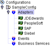
Right-click the Siebel node and select Add Target.
Click OK.
When you select Siebel 6.2 or lower (COM):
In the User Agent File field, type the name of the configuration file.
In the Password field, type the password associated with the user name.
In the Repository field, type the Siebel Repository where Application Explorer looks for metadata describing Business Services, Business Objects, and Integration Objects.
If no repository is specified, a full list of objects from all available repositories will be returned. If a specified repository is not found, an empty list of objects will be returned.
When you select 6.3 or higher (JDB):
In the Gateway Server field, type the name of the server.
In the Enterprise Name field, type the appropriate name.
In the Siebel Server field, type the name of your Siebel server.
Do not populate this field for Siebel 7.7.1.
In the User field, type the user name.
In the Password field, type the password associated with the user name.
Click the Advanced tab and verify the following:
Language
Object Manager
For Siebel 7.0.3, the default Object Manager is EAIObjMgr. For Siebel 7.7, the default is EAIObjMgr_enu.
Repository Manager
If no repository is specified, a full list of objects from all available repositories will be returned. If a specified repository is not found, an empty list of objects will be returned.
The configuration parameters supplied are those used by Siebel client applications to connect to the Siebel system. For more information about these parameters, see your Siebel documentation or ask your Siebel system administrator.
Click OK.
In the left pane, the target you create appears under the Siebel node.
To connect to a defined target:
Expand the Siebel node and click the target name to which you want to connect.
In the right pane, enter the password for that target.
In the left pane, right-click the target name and select Connect.
The icon changes, and a plus sign(+) next to the target icon indicates that you are connected to the Siebel system.
You can browse available Business Objects, Business Services, and Integration Objects in the Siebel system.
Although you can maintain multiple open connections to different application systems, it is good practice to close connections when not in use.
In the left pane, ensure the target you wish to edit is disconnected.
Right-click the target and select Edit.
The Edit pane opens on the right.
Modify the target information.
Click OK.
You can delete a target, rather than just disconnecting and closing it. When you delete the target, the node disappears from the list of Siebel targets in the left pane of the explorer.
To delete a target:
In the left pane, select the target.
Right-click the target and select Delete.
A confirmation dialog box opens.
Click OK to delete the target you selected.
The SiebelConnection node disappears from the left pane.
Application Explorer gives you the flexibility of viewing all Siebel application system objects. One benefit of this flexibility is that you can gain an understanding of the Siebel data structure. You can review parameters, data types, and other attributes of the Siebel data in the right pane.
To view metadata:
If you have not started the explorer, start Application Explorer and connect to your Siebel system.
In the left pane, expand the Business Object or Business Service containing the component for which you want to generate schema.
Expand the Business Object or Business Service node.
Expand the Business Component or the Business Service node to view the objects under it.
For a Business Component, select the node in which you are interested, for example, Account.

For a Siebel Business Service, select the object in which you are interested, for example, addAccount.

In the right pane, click the ellipsis (...) in the Table row of the properties table.
The metadata table appears in the right pane.
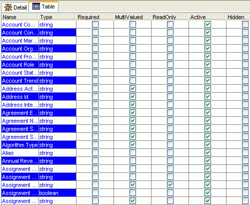
You can create service schemas for Business Services and Business Components using Application Explorer.
The following topic, "Creating an XML Schema for a Siebel Business Object or Business Service" describes how to create schemas for the adapter when you deploy the OracleAS Adapter for Siebel for use either in a JCA (J2EE Connector Architecture) environment or a Web services environment.
See "Creating a Web Service or Business Service" if you plan to deploy the OracleAS Adapter for Siebel in a Web services environment.
Creating an XML Schema for a Siebel Business Object or Business Service
You create schemas for Siebel Business Service methods (for example, the Add method) and Business Components using Application Explorer. After you create a schema, you can use it to generate service request and response schemas for the Business Service or Business Component.
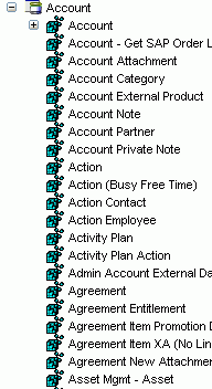
Siebel Business Objects contain one or more Siebel Business Components. You can view Business Components by clicking the associated Business Object.
The following illustration shows the Account Business Object expanded to display all Business Components.
Creating an XML Schema for a Siebel Business Component or Business Service
To generate service request and response schemas for a Business Component or Business Service:
If you have not started the explorer, start Application Explorer and connect to your Siebel system.
In the left pane, expand the Business Object or the Business Service node.
Expand the Business Component or Business Service to view the objects under it.
For a Business Component, expand the component containing the node you wish and select the method for which you want to create a schema, for example, insert.

For a Siebel Business Service, expand the Business Service node containing the object for which you want to create schema.

Right-click the node and select Generate Schema.
Application Explorer accesses the Siebel repository and builds schemas.
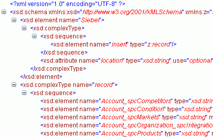
Schema tabs similar to the following appear in the right pane.

To view a schema, click the ellipsis tab corresponding to the schema you want to view.
The schema appears on the right.
You can generate a business service (also known as a Web service) for Siebel objects you wish to use with your adapter after you have properly configured the servlet BSE.
|
Note: In a J2EE Connector Architecture (JCA) implementation of adapters, Web services are not available. When the adapters are deployed to use the OracleAS Adapter JCA, the Common Client Interface provides integration services using the adapters. |
As an example, the following procedure describes the creation of a Web service for a Business Object.
To generate a Web service for a Siebel Business Object:
If you have not already connected, connect to your Siebel system.
Expand a Business Object node.
Expand the Business Component for which you want to create a Web service.

Expand the object and select a method for creating the Web service, for example, QueryWithView under Account.
Right-click the node from which you want to create a business service and select Create Business Service.
The Create Web Service dialog box opens.
You can add the business object as a method for a new Web service or as a method for an existing one.
From the Existing Service Names list, select either <new service> or an existing service.
Specify a service name if you are creating a new service. This name identifies the Web service in the list of services under the Business Services node.
Type a description for the service (optional).
Select one of the available licenses.
Click Next.
The License and Method dialog box opens.
In the License field, select one or more license codes to assign to the Web service. To select more than one, hold down the Ctrl key and click the licenses.
In the Method Name field, type a descriptive name for the method.
In the Description field, type a brief description of the method.
Click OK.
Application Explorer switches the view to the Business Services node, and the new Web service appears in the left pane.
After you create a Web service for the Siebel Business Object, test it to ensure it functions properly. Application Explorer includes a test tool for testing a Web service.
Testing a Web Service for a Business Object
In the left pane of Application Explorer, expand the Business Services node.
Select the name of the business service you want to test.

Expand the Methods node under the service and select the method you want to test.
The test option appears in the right pane.
If you are testing a Web service that requires XML input, an input field appears.
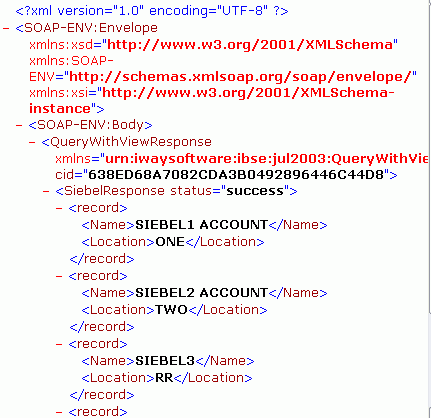
Click Invoke.
Application Explorer displays the results in the results pane.
Testing a Web Service for a Business Service
After you create a Web service for the Siebel Business Service, test it to ensure it functions properly. Application Explorer includes a test tool for testing a Web service.
If it is not expanded, expand the Business Services node.
Expand the Services node.
Select the name of the business service you want to test.
Expand the Methods node and select the name of the method you want to test.
The test option appears in the right pane.
If you are testing a Web service that requires XML input, an input field appears.
Provide the appropriate input.
Click Invoke.
Application Explorer displays the results in the results pane.
Events are generated as a result of a specific business condition being satisfied or triggered in the Siebel system. You can use events to trigger an action in your application. For example, an update to a database can reflect an update to customer information. If your application must perform when this happens, your application is a consumer of this event.
After you create a connection to your application system, you can add events using Application Explorer. To configure an event, you must create a port and a channel.
Port
A port associates a particular business object exposed by an adapter with a particular disposition. A disposition defines the protocol and location of the event data. The port defines the end point of the event consumption. See "Creating an Event Port" for more information.
Channel
A channel represents configured connections to particular instances of back-end or other types of systems. A channel binds one or more event ports to a particular listener managed by an adapter. See "Creating a Channel" for more information.
|
Note: OC4J currently conforms to JCA 1.0, which does not call for event capabilities. When conforming to JCA 1.0, only service interactions are supported. |
You can listen for Siebel Integration Object events by configuring ports and channels. Before you create the ports and channels, you must create a schema. To create XML schemas for Siebel Integration Objects, you must first generate XDR schemas using the Siebel Tools Schema Wizard.
The XDR schema is used as input to Application Explorer when generating schemas for integration objects. After you generate the XDR schema, Application Explorer uses the XDR file to generate the XML schema.
The OracleAS Adapter for Siebel supports access to Siebel Integration Objects by using Siebel XML to handle events. Using Siebel Integration Objects through supported transports requires Siebel workflows.
|
Note: For releases prior to Siebel 6.3, the Siebel Tools Schema Wizard creates only DTD schemas. You must transform these schemas manually, or by using other tools, into XDR files before Application Explorer can use them as input to create XML schemas. In addition, you must include the SiebelMessage tag reference in your XDR file. |
Creating a Siebel XDR Schema for a Siebel Integration Object
To generate a Siebel XDR schema:
Log on to Siebel Tools.
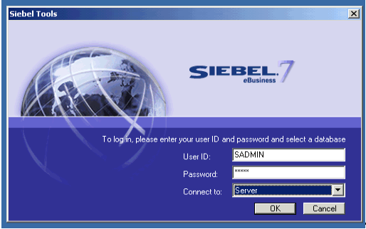
Type your user ID and password.
Select a database from the list.
Click OK.
The Siebel Tools window opens. Integration Objects appear in the right pane.
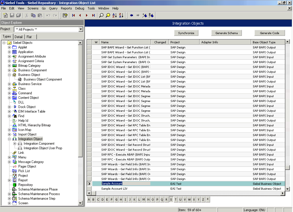
To create a schema, select an Integration Object, for example, Sample Account.
Click Generate Schema.
The Generate XML Schema wizard opens.
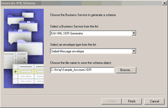
From the Select a Business Service list, select EAI XML XDR Generator.
From the Select an envelope type list, select Siebel Message envelope.
In the Choose the file name field, specify a file name for the XDR schema and a directory where it can be accessed by Application Explorer.
|
Note: The XDR schema file must be saved to a directory on the same computer as Application Explorer. |
Click Finish.
Now you can use Application Explorer to generate XML schemas for the Siebel Integration Object.
Creating a Schema from a Siebel XDR Schema
After you create the Siebel XDR schema for a selected Siebel Integration Object, you can create an XML schema using Application Explorer.
You must supply Application Explorer with the location of the previously created Siebel XDR schema for the particular integration object selected.
|
Note: The XDR file must be on the same computer as Application Explorer or be available through a mapped connection to another drive or machine. |
To create a schema from a Siebel XDR Schema:
In Application Explorer, expand the Integration Objects node to browse the Integration Objects in the Siebel system.
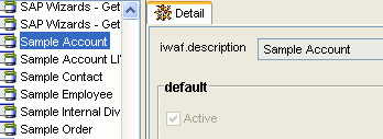
Scroll down and select an integration object, for example, Sample Account.
To generate event schema, right-click the object and choose Add event.
Click Add.
The Schemas pane opens.
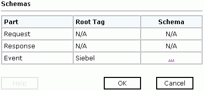
To view the XML for a schema, click the Event Schema tab.
The results appear in the right pane.
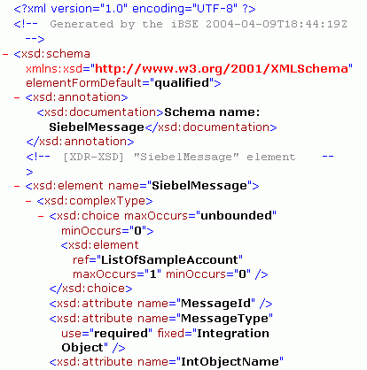
Click the browser Back button to return.
A directory structure is created to store the schemas.
You are now ready to configure ports and channels for Siebel Integration Objects.
To create an event port for Siebel Integration Objects, you must first indicate the location of the XDR schema for that object.
You can create an event port from the Events node for Siebel Integration Objects. To create event ports for Siebel Business Objects and Siebel Business Services, you must use the Events node.
Creating an Event Port from the Adapters Node
For Siebel Integration Objects, you can bypass the Events node and create an event port directly from the Adapters node.
Select the Integration Object event you created.
Right-click the Integration Object event and select Add Port.
The Add Port dialog box opens.
Type a name for the event port and provide a brief description.
From the list, select the required disposition, for example, RMI.
In the URL field, type the disposition url.
Click OK.
The following procedure describes how to create an event port from the Events node for an RMI disposition using Application Explorer.
To create an event port for Siebel Integration Objects, you must first indicate the location of the XDR schema for that object. See "Creating a Schema from a Siebel XDR Schema" for more information.
You also can create an event port directly from the Adapters node. See "Creating an Event Port from the Adapters Node" for more information.
Creating an Event Port for RMI
To create a specific event port for RMI:
Click the Events node.
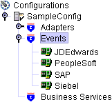
Expand the Siebel node.
Right-click the Ports node and select Add Port.
The Add Port dialog box opens.
Type a name for the event port and provide a brief description.
From the Protocol list, select RMI.
In the URL field, specify a destination file to which the event data is written using the following format:
rmi://host:port;RemoteObject=[APPNAME];errorTo=[pre-defined port name or another disposition url]
From the Disposition protocol list, select RMI.
The following table defines the parameters for the disposition.
| Parameter | Description |
|---|---|
| host | The host name or IP address from which the RMI server accepts RMI requests. If you omit this attribute, the RMI server will accept RMI requests from any host. |
| port | The port number on which the RMI server listens for RMI requests. |
| RemoteObject | A home or Enterprise JavaBeans (EJB) object. |
| errorTo | Predefined port name or another disposition URL to which error logs are sent. |
Click OK.
The port appears under the ports node in the left pane. In the right pane, a table appears that summarizes the information associated with the event port you created.
You are ready to associate the event port with a channel. See "Creating a Channel" for more information.
In the left pane, select the event port you want to edit.
Right-click the port and select Edit.
The Edit Port pane opens.
Make the required changes and click OK.
Select the event port you want to delete.
Right-click the port and select Delete.
A confirmation dialog box opens.
To delete the event port you selected, click OK.
The event port disappears from the list in the left pane.
The following procedure describes how to create a channel for your event. All defined event ports must be associated with a channel. Three channel types are available:
HTTP
MQ Series
File
|
Note: OC4J currently conforms to JCA 1.0, which does not call for event capabilities. When conforming to JCA 1.0, only service interactions are supported. |
The Events window opens. The adapters that appear in the left pane support events.
In the left pane, expand the Siebel node.
Right-click channels and select Add channel.
The Add Channel dialog box opens.
Type a name for the channel, for example, NewChannel.
Type a brief description.
From the list, select HTTP Listener.
The following image shows the Select Ports dialog box.
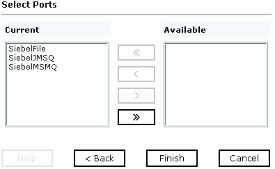
Select an event port from the list of current ports.
To transfer the port to the list of available ports, click the double right (>>) arrow. To associate all the event ports, control-click to select each port or click one port and press Control+A. Then, click the double right (>>) arrow.
Click Next.
When the dialog box opens, type the system information as specified in the following table.
| Parameter | Description |
|---|---|
| Port | Port on which to listen for Siebel event data. |
| Server port | Port on which the host database is listening. |
| Synchronization Type | Possible values are:
REQUEST REQUEST_RESPONSE REQUEST_ACK |
Click OK.
The summary pane opens.
A summary provides the channel description, channel status, and available ports. All the information is associated with the channel you created.The channel also appears under the channels node in the left pane

An X over the icon indicates that the channel is currently disconnected. You must start the channel to activate your event configuration.
Right-click the channel and select Start the channel.
The channel you created becomes active.
The X that was over the icon in the left pane disappears.
To stop the channel, right-click the channel and select Stop the channel.
To create an MQ Series listener:
Click the Events node.
The Events window opens. The adapters that appear in the left pane support events.
In the left pane, expand the Siebel node.
The ports and channels nodes appear.
Right-click the channels node and select Add channel.
The Add a new channel pane opens.
Type a name for the channel, for example, NewChannel.
Type a brief description.
From the list, select MQ Series Listener.
The following image shows the Select Ports dialog box.

Select an event port from the list of current ports.
To transfer the port to the list of available ports, click the double right (>>) arrow.To associate all the event ports, control-click to select each port or click one port and press Control+A. Then, click the double right (>>) arrow.
Click Next.
When the dialog box opens, type the system information as follows.
In the Request tab, enter values for the following parameters:
| Parameter | Description |
|---|---|
| Queue manager name | The host on which the MQ Server is located (MQ Client only). |
| MQ server host for MQClient operation | Port on which the host database is listening. |
| MQ server port for MQClient operation | The number to connect to an MQ Server queue manager (MQ client only).
REQUEST REQUEST_RESPONSE REQUEST_ACK |
| MQ server channel for MQClient operation | The case-sensitive name of the channel that connects with the remote MQ Server queue manager (MQ client only). The default channel name for MQSeries is SYSTEM.DEF.SVRCONN. |
| Document type XML | Leave the default selection. |
| Request queue name | Queue where the message is routed and where request documents are received. The name of the queue is case-sensitive and conforms to the following format:
Host\queue type$\qName Host Is the machine name where the MQ Series queuing system is running. queue type Private queues are queues that are not published in Active Directory and appear only on the local computer where they reside. Private queues are accessible only by Message Queuing applications that recognize the full path name or format name of the queue. qName Is the name of the queue where messages are placed, for example, iwaykxc1\Private$\siebel |
In the Response tab, enter values for the following parameters:
In the Advanced tab, enter values for the following parameters.
| Parameter | Definition |
|---|---|
| Error Directory | Directory to which documents with errors are written. |
| Message wait interval (msec) | The interval (in milliseconds) when to check for new input. The default is 3 seconds. Optional. |
| Mode of operation | Choose Sequential or Threaded.
|
| Thread limit | If you selected threaded processing, indicate the maximum number of requests that can be processed simultaneously. |
Click OK.
The summary pane opens.
A summary provides the channel description, channel status, and available ports. All the information is associated with the channel you created. The channel also appears under the channels node in the left pane
An X over the icon indicates that the channel is currently disconnected. You must start the channel to activate your event configuration.
Right-click the channel and select Start the channel.
The channel you created becomes active.
The X that was over the icon in the left pane disappears.
To stop the channel, right-click the channel and select Stop the channel.
The Events window opens. The adapters that appear in the left pane support events.
In the left pane, expand the Siebel node.
The ports and channels nodes appear.
Right-click the channels node and select Add Channel.
The Add Channel dialog box opens.
Type a name for the channel, for example, NewChannel.
Type a brief description.
From the list, select File Listener.
The following image shows the Select Ports dialog box.

Select an event port from the list of current ports.
To transfer the port to the list of available ports, click the double right (>>) arrow button. To associate all the event ports, control-click to select each port or click one port and press Control+A. Then, click the double right (>>) arrow button.
Click Next.
When the dialog box opens, type the system information as follows.
In the Request tab, enter values for the following parameters:
| Parameter | Description |
|---|---|
| Polling Location | The target file system location for the Siebel XML file. |
| File Mask | The file name to be used for the output file generated as a result of this operation. |
In the Response tab, enter values for the following parameters:
| Parameter | Definition |
|---|---|
| Synchronization Type | Choose from three options:
|
| Response/Ack Directory | Directory where responses or acknowledgments are sent. |
In the Advanced tab, enter values for the following parameters:
| Parameter | Definition |
|---|---|
| Error Directory | Directory to which documents with errors are written. |
| Poll interval (msec) | The interval (in milliseconds) when to check for new input. The default is 3 seconds. Optional. |
| Processing Mode | Choose Sequential or Threaded.
|
| Thread limit | If you selected threaded processing, indicate the maximum number of requests that can be processed simultaneously. |
Click OK.
A summary provides the channel description, channel status, and available ports. All the information is associated with the channel you created.The channel also appears under the channels node in the left pane
An X over the icon indicates that the channel is currently disconnected. You must start the channel to activate your event configuration.
Right-click the channel and select Start the channel.
The channel you created becomes active.
The X that was over the icon in the left pane disappears.
To stop the channel, right-click the channel and select Stop the channel.