|
Oracle® BPEL Process Manager Developer's Guide
10g Release 2 (10.1.2) B14448-03 |
|
 Previous |
 Next |
|
Oracle® BPEL Process Manager Developer's Guide
10g Release 2 (10.1.2) B14448-03 |
|
 Previous |
 Next |
This appendix describes the activities available for use when designing a BPEL process in JDeveloper BPEL Designer.
This appendix contains the following topics:
As you create and open activities such as scope, assign, and others for the first time in JDeveloper BPEL Designer, the message Invalid Settings appears at the top of the activity window. This is because you have not yet entered details. If the Validate process when loading diagram option is selected, the message always appears. You can ignore this message. As you enter and correctly apply your details, the message disappears.
To turn this option off for the current project, perform the following steps:
Right-click in the JDeveloper BPEL Designer Diagram View and select Diagram Properties.
Deselect the Validate process when loading diagram option on the Diagram Properties window.
Click OK.
Select Save All from the File main menu.
To disable this message for all new projects going forward, perform the following steps:
Select Preferences > BPEL Editor from the Tools main menu in JDeveloper BPEL Designer.
Deselect the Validate process when loading diagram option.
Click OK.
Any projects created after this point do not display the Invalid Settings message.
JDeveloper BPEL Designer includes a series of activities that are available for dragging and dropping into a BPEL process. These activities enable you to perform specific tasks within a process. This section provides a brief overview of these activities and provides references to other documentation that describes how to use these activities:
This section contains the following topics:
|
See Also: The following documentation for additional details about activities:
|
While each activity performs specific tasks, many activities include tabs that enable you to perform similar tasks. This section describes these common tabs.
The Sensors tab displays on all activities and enables you to create sensors for capturing details about an activity.
The Correlation Sets tab displays in invoke, receive, and reply activities, the onMessage branch of pick activities, and the OnMessage variant of event handlers. Correlation sets address complex interactions between a process and its partners by providing a method for explicitly specifying correlated groups of operations within a service instance. A set of correlation tokens is defined as a set of properties shared by all messages in the correlated group.
The Adapters tab displays in invoke, receive, and reply activities, and the onMessage branch of pick activities. You create header variables for use with the Advanced Queuing (AQ), File, FTP, and Java Message Service (JMS) adapters.
The Annotations tab displays on all activities and enables you to provide descriptions in activities in the form of code comments and name and pair value assignments.
|
See Also:
|
This activity provides a method for data manipulation, such as copying the contents of one variable to another. This activity can contain any number of elementary assignments.
When you double-click the assign icon, the Assign window appears. You can perform the following tasks:
Click the General tab to provide the assign activity with a meaningful name.
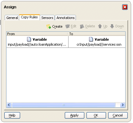
Click the Copy Rules tab and the Create icon shown in Figure C-1 to access the Create Copy Rule window. This enables you to copy the contents of the source element (variable, expression, XML fragment, or partner link) in the From field to the contents of the destination element in the To field. You can also select a part (typically the payload) and an XPath query (a language for addressing parts of an XML document).
Figure C-1 Copy Rules Tab of Assign Activity WIndow

If an assign activity contains more than one bpelx:append setting, it must be split into two assign activities. Otherwise, JDeveloper BPEL Designer moves the bpelx:append to the end of the list each time, which can cause problems. As a workaround, move it manually.
|
See Also: The following documentation for many examples of using the assign activity:
|
This activity enables you to create optional fault handling logic to catch and manage exceptions. Fault handling is associated with a scope activity. Fault handling's goal is to undo the incomplete and unsuccessful work of a scope activity in which a fault has occurred.
Fault handlers in a scope activity enable you to create a set of custom fault-handling activities, which are defined as catch activities. Each catch activity is defined to intercept a specific type of fault.
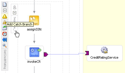
Figure C-2 shows the Add Catch Branch icon inside a scope activity that you click to create a catch activity. Figure C-3 shows an example of a catch activity on the right side of the scope activity. Within the area defined as Drop Activity Here, you drag and drop additional activities to create fault handling logic to catch and manage exceptions.
For example, a client provides a social security number to a Credit Rating service when applying for a loan. This number is used to perform a credit check. If a bad credit history is identified or the social security number is identified as invalid, an assign activity inside the catch activity notifies the client of the loan offer rejection. The entire loan application process is terminated with a terminate activity.
Figure C-2 Creating an Add Catch Activity

|
See Also: The following documentation for examples of using the catch activity:
|
This activity invokes compensation on an inner scope activity that has already successfully completed. This activity can be invoked only from within a fault handler or another compensation handler. Compensation occurs when a process cannot complete several operations after already completing others. The process must return and undo the previously completed operations. For example, assume a process is designed to book a rental car, a hotel, and a flight. The process books the car and the hotel, but is unable to book a flight for the correct day. In this case, the process performs compensation by unbooking the car and the hotel.The compensation handler is invoked with the compensate activity, which names the scope on which the compensation handler is to be invoked.
When you double-click the compensate icon, the Compensate window shown in Figure C-4 appears. You can perform the following tasks:
Click the General tab to provide the activity with a meaningful name and select the scope activity on which the compensation handler is to be invoked.
This activity enables you to insert a no-operation instruction into a process. This activity is useful when you need to use an activity that does nothing (for example when a fault needs to be caught and suppressed). Figure C-5 shows the empty activity.
A flow activity enables you to specify one or more activities to be performed concurrently. A flow activity completes when all activities in the flow have finished processing. Completion of a flow activity includes the possibility that it can be skipped if its enabling condition is false.
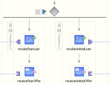
For example, assume you use a flow activity to enable two loan offer providers (United Loan service and Star Loan service) to start in parallel. In this case, the flow activity contains two parallel activities – the sequence to invoke the United Loan service and the sequence to invoke the Star Loan service. Each service can take an arbitrary amount of time to complete their loan processes.
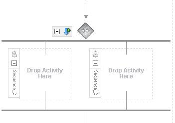
Figure C-6 shows an initial flow activity with its two panels for parallel processing. You drag and drop activities into both panels to create parallel processing. When complete, a flow activity looks like that shown in Figure C-7.
Figure C-6 Flow Activity (At Time of Creation)

Figure C-7 Flow Activity (After Design Completion)

|
See Also: The following documentation for examples of using the flow activity:
|
This activity enables you to create activities within a flow. You specify the number of branches of these activities to create.
Figure C-8 shows a flowN activity.
|
See Also:
|
This activity enables you to specify an operation you want to invoke for the service (identified by its partner link). The operation can be one-way or request-response on a port provided by the service. You can also automatically create variables in an invoke activity. An invoke activity invokes a synchronous service or initiates an asynchronous Web service.
The invoke activity opens a port in the process to send and receive data. It uses this port to submit required data and receive a response. For synchronous callbacks, only one port is needed for both the send and the receive functions.
When you double-click the invoke icon, the Invoke window shown in Figure C-9 appears. You can perform the following tasks:
Provide the activity with a meaningful name.
Select the partner link for which to specify an operation
Select the operation to be performed
Automatically create a variable or select an existing variable in which to transport the data (payload)
|
See Also: The following documentation for many examples of using the invoke activity:
|
This activity enables you to add custom Java code to a BPEL process using the Java BPEL exec extension <bpelx:exec>. This is useful when you already have Java code that can perform a function, and want to use this existing code instead of starting over.
When you double-click this activity, the Edit Java Embedding window shown in Figure C-10 appears.
If you use this activity, ensure that you add the JAR files to the JDeveloper BPEL Designer classpath or put them in the Oracle_Home\integration\jdev\jdev\lib\ext directory to ensure that your project compiles properly during design time.
In addition, place the corresponding class files in the Oracle_Home\integration\orabpel\system\classes directory.
Perform the following Java JAR file configuration steps to ensure correct run time behavior. This example describes the configuration steps for Windows operating systems. Perform similar steps for UNIX operating systems.
Add the files into the BPEL client bpelc CLASSPATH:
Open Oracle_Home\integration\orabpel\bin\obsetenv.bat. For UNIX operating systems, the file is named obsetenv.sh.
Edit the file as follows:
@REM set MY_CLASSES_DIR=%CLASSPATH%
set MY_CLASSES_DIR=%OB_HOME%\system\classes
set MY_CLASSPATH=%MY_CLASSES_DIR%;your_jar_files
Add the files into the Oracle BPEL Server bpelc CLASSPATH in either of two ways:
Open Oracle_Home\integration\orabpel\domains\default\config\domain.xml (if the default domain is being used).
Edit the file as follows:
<property id="bpelcClasspath">
   <name>BPEL process compiler classpath</name>
   <value>your_jar_files;...</value>
   <comment>...</comment>
</property>
Restart Oracle BPEL Server.
or
Go to Manage BPEL Domain > Configuration on Oracle BPEL Console.
Go to the bpelcClasspath property.
Enter your_jar_files; in the Value field.
Click Apply.
Restart Oracle BPEL Server.
Add the files into the Oracle Application Server CLASSPATH:
Open Oracle_Home\integration\orabpel\system\appserver\oc4j\j2ee\home\config\application.xml.
Edit the file as follows:
<!-- ORABPEL -->
    <library path="your_jar_files"/>
    <library path="C:\OraBPELPM_1\integration\orabpel\system\classes"/>
|
See Also:
|
This activity enables you to send notification about an event to a user, group, or destination address. You can send a notification by e-mail, voice mail, fax, pager, or short message service (SMS).
For example, an Online Shopping business process of an online bookstore sends a courtesy notification message to you after the items are shipped. The business process calls the notification service with your user ID and notification message. The notification service gets the notification address (e-mail address in this case) from Oracle Internet Directory and sends the message to your e-mail address.
When you drag and drop a notification activity into JDeveloper BPEL Designer, a Notification wizard starts and prompts you for the above information.
Figure C-11 shows the Notification wizard.
|
See Also:
|
This activity enables you to define the external services with which your process interacts. A partner link type characterizes the conversational relationship between two services by defining the roles played by each service in the conversation and specifying the port type provided by each service to receive messages within the context of the conversation. For example, if you are creating a process to interact with a Credit Rating Service and two loan provider services (United Loan and Star Loan), you create partner links for all three services.
When you double-click the partnerlink icon, the Partner Link window shown in Figure C-12 appears. You can provide the following details:
A meaningful name for the service
The Web services description language (WSDL) file of the external service
The actual service type (defined as Partner Link Type)
The role of the process requesting the service (defined as My Role)
The role of the service (defined as Partner Role)
|
See Also: The following documentation for many examples of using the PartnerLink activity: |
This activity waits for the occurrence of one event in a set of events and performs the activity associated with that event. The occurrence of the events is often mutually exclusive (the process either receives an acceptance or rejection message, but not both). If more than one of the events occurs, then the selection of the activity to perform depends on which event occurred first. If the events occur nearly simultaneously, there is a race and the choice of activity to be performed is dependent on both timing and implementation.
The pick activity provides two branches, each one with a condition. When you double-click the pick icon, the pick activity shown in Figure C-13 appears and displays these two branches: onMessage (on the left) and onAlarm (on the right). The onMessage branch contains the code for receiving a reply, for example, from a loan service. The onAlarm branch contains the code for a timeout, for example, after one minute. Whichever branch completes first is executed; the other branch is not. The branch that has its condition satisfied first is executed.
If you add correlations to an OnMessage branch of a Pick activity in JDeveloper BPEL Designer, the correlations syntax is placed after the assign activity syntax. The correlation syntax must go before the assign activity.
As a workaround, perform the following steps:
Create a correlation set in JDeveloper BPEL Designer.
Assign this to the OnMessage branch.
Complete the remaining design tasks.
Before making or deploying the BPEL process, move the correlation syntax before the assign activity in the BPEL source code.
|
See Also:
|
This activity specifies the partner link from which to receive information and the port type and operation for the partner link to invoke. This activity waits for an asynchronous callback response message from a service, such as a loan application approver service. While the BPEL process is waiting, it is dehydrated (compressed and stored) until the callback message arrives. The contents of this response are stored in a response variable in the process.
When you double-click the receive icon, the Receive window shown in Figure C-14 appears. You can perform the following tasks:
Provide the receive activity with a meaningful name.
Select the partner link service for which to specify an operation
Select the operation to be performed
Automatically create a variable or select an existing variable in which to transport the callback response
|
See Also: The following documentation for many examples of using the receive activity:
|
This activity allows the process to send a message in reply to a message that was received through a receive activity. The combination of a receive activity and a reply activity forms a request-response operation on the WSDL port type for the process.
Figure C-15 shows the reply activity.
|
See Also:
|
This activity consists of a collection of nested activities that can have their own local variables, fault handlers, compensation handlers, and so on. A scope activity is analogous to a { } block in a programming language.
Each scope has a primary activity that defines its behavior. The primary activity can be a complex structured activity, with many nested activities within it to arbitrary depth. The scope is shared by all the nested activities.
When you double-click the scope icon, the Scope window shown in Figure C-16 appears. Define appropriate activities inside the scope activity.
|
See Also: The following documentation for many examples of using the scope activity: |
This activity enables you to define a collection of activities to be performed in sequential order. For example, you may want the following activities performed in a specific order:
A customer request is received in a receive activity.
The request is processed inside a flow activity that enables concurrent behavior.
A reply message with the final approval status of the request is sent back to the customer in a reply activity.
A sequence activity makes the assumption that the request can be processed in a reasonable amount of time, justifying the requirement that the invoker wait for a synchronous response (because this service is offered as a request-response operation).
When this assumption cannot be made, it is better to define the customer interaction as a pair of asynchronous message exchanges.
When you double-click the sequence icon, the sequence activity shown in Figure C-17 appears. Define appropriate activities inside the sequence activity.
This activity consists of an ordered list of one or more conditional branches defined in a case branch, followed optionally by an otherwise branch. The branches are considered in the order in which they appear. The first branch whose condition is true is taken and provides the activity performed for the switch. If no branch with a condition is taken, then the otherwise branch is taken. If the otherwise branch is not explicitly specified, then an otherwise branch with an empty activity is assumed to be available. The switch activity is complete when the activity of the selected branch completes.
A switch activity differs in functionality from a flow activity. For example, a flow activity enables a process to gather two loan offers at the same time, but does not compare their values. To compare and make decisions on the values of the two offers, a switch activity is used. The first branch is executed if a defined condition (inside the case branch) is met. If it is not met, the otherwise branch is executed.
Figure C-18 shows a switch activity with two defined branches.
|
See Also: The following documentation for examples of using the switch activity:
|
A terminate activity enables you to end the tasks of an activity (for example, the fault handling tasks in a catch branch). For example, if a client's bad credit history is identified or a social security number is identified as invalid, a loan application process is terminated, and the client's loan application document is never submitted to the service loan providers.
Figure C-19 shows a terminate activity at the end of a catch branch of a scope activity.
|
See Also: The following documentation for examples of using the terminate activity:
|
This activity generates a fault from inside the business process.
When you double-click the throw icon, the Throw window shown in Figure C-20 appears.
|
See Also: The following documentation for examples of using the throw activity:
|
This activity enables you to create a transformation that maps source elements to target elements (for example, incoming purchase order data into outgoing purchase order acknowledgment data).
When you double-click the transform icon, the Transform window shown in Figure C-21 appears. This window enables you to perform the following tasks:
Define the source and target variables and parts to map
Specify the transformation mapper file
Click the second icon (the Create Mapping icon) to the right of the Mapper File field to access a window for graphically mapping source and target elements. This window enables you to drag and drop (map) a source element to a target element.
|
See Also: The following documentation for examples of using the transform activity:
|
This activity enables you to start the Workflow wizard. A workflow describes the tasks, input or output information, and procedural steps that must be performed by users or groups as part of the end-to-end business process. For example, an insurance company can design a workflow application to ensure that a claim is handled consistently from initial call to final settlement. The workflow application ensures that each person handling the claim uses the correct online form and successfully completes their step before enabling the process to proceed to the next person and procedural step.
This wizard enables you to create a workflow model to manage and enforce the consistent handling of work. After wizard creation, you can also further customize a workflow pattern by directly modifying the configuration files. At run time, the workflow results in the creation of tasks that can be accessed through the Oracle BPEL Worklist Application.
When you drag and drop a user task, the Welcome window shown in Figure C-22 appears.
|
See Also: The following documentation for examples of using the user task activity and workflows:
|
This activity allows a process to specify a delay for a certain period of time or until a certain deadline is reached. A typical use of this activity is to invoke an operation at a certain time. This activity allows you to wait for a given time period or until a certain time has passed. Exactly one of the expiration criteria must be specified.
When you double-click the wait icon, the Wait window shown in Figure C-23 appears.
|
See Also: The following documentation for examples of using the wait activity:
|
This activity supports repeated performance of a specified iterative activity. The iterative activity is repeated until the given while condition is no longer true.
When you double-click the while icon, the While window shown in Figure C-24 appears. You can enter expressions in this window.
|
See Also: The following documentation for examples of using the while activity:
|