| Oracle® Retail Xstore Suite 17.0/Merchandising 16.0.1 Implementation Guide Release 17.0 E90914-06 |
|

 Previous |
 Next |
| Oracle® Retail Xstore Suite 17.0/Merchandising 16.0.1 Implementation Guide Release 17.0 E90914-06 |
|
Previous |
Next |
This chapter describes how to install, deploy, and configure the RTLog Generator application.
RTLog Generator is a Java and XML based web application that exposes a Spring-JAXWS implemented SOAP web service. It is distributed as a web archive along with a configuration zip file ready to be deployed on an Oracle WebLogic 12c server.
This chapter uses Microsoft Windows path format as the example for paths.
The RTLog Generator application is shipped with a configuration zip file (rtlog-gen-config.zip) which should be used to externally configure and extend the RTLog Generator's functionality.
|
Note: Bounce the WebLogic server after making any configuration level changes. |
Starting from Xstore release 17.0, the RTLog Generator application is shipped with two configuration zip files:
rtlog-gen-config-resa-cs.zip
rtlog-gen-config-resa-onprem.zip
To integrate with ReSA on cloud, rtlog-gen-config-resa-cs.zip should be used to externally configure and extend the RTLog Generator's functionality.
To integrate with ReSA on premise, rtlog-gen-config-resa-onprem.zip should be used to externally configure and extend the RTLog Generator's functionality.
To set up the external configuration features:
Extract the configuration file's content into the C:\<rtlog-gen-config> directory if installing on Microsoft Windows or /usr/local/<rtlog-gen-config> on Linux OS. These directories are the default locations where the RTLog Generator application will look for the configuration files. These default locations can be overridden/changed by using one of the following ways:
Pass a JVM argument to the server startup script and bounce the server:
-Drtloggen.config.dir=C:/<custom_directory>/
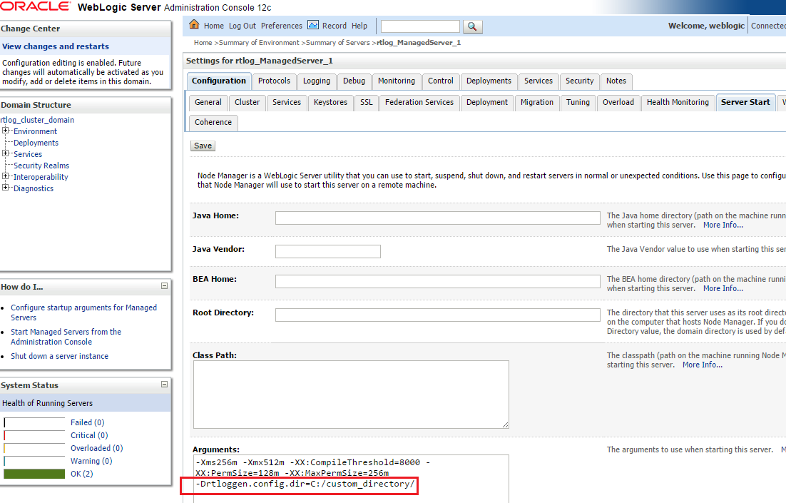
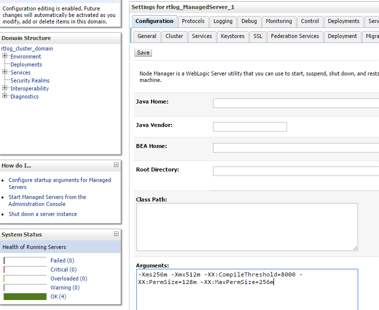
If the WebLogic domain is created with a Node manager, the same argument can be passed from the Administration Console in the Arguments field. See Figure 6-1.
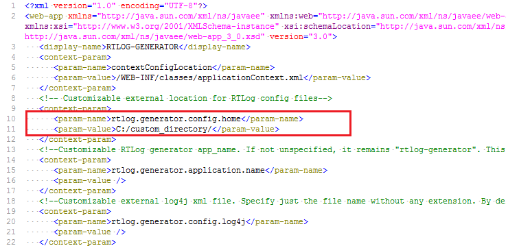
Specify the context-param field in the RTLog Generator WAR file. This requires opening up the WAR file and making the required changes. Update the web.xml file as shown in the following example:
<context-param>
    <param-name>rtlog.generator.config.home</param-name>
    <param-value>C:/<custom_directory>/</param-value>
</context-param>
The JVM argument takes the precedence over the default location, that is, C:\<rtlog-gen-config>. If either of the two does not exist, the context parameter is used. If nothing is specified, the RTLog Generator application will fail on startup with error messages in the server logs.
Once the configuration file is extracted to the configured directory, verify the following files:
rtlogconfig.properties:
This file contains three properties (key value pairs):
processingDir: This directory path specifies the location that RTLog Generator will use to build its RTLog files as it receives data from Xstore Office. This directory needs to be created manually.
resaFileDropDir: This directory path specifies the destination for the RTLog files this system is producing. It should be configured to the location where ReSA is looking to receive the RTLog files. This directory needs to be created manually.
clusterNodeNumber: This property should only be enabled when running in a clustered environment. For more information, see "WebLogic Cluster Setup".
Following is an example of the three properties:
processingDir = C:/RTLOG_Weblogic/Output/Store/RTLOGS
resaFileDropDir = C:/RTLOG_Weblogic/Output/ReSA
clusterNodeNumber = 1
RTLogFormatConfig.xml:
This file specifies the format of the RTLog record as specified by ReSA. You do not make any changes to this file.
rtlog-generator-log4j.xml: This file configures the logging levels for the RTLog Generator application.
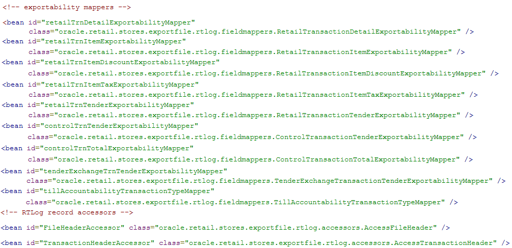
RTLogMappingBean.xml:
This is a spring configuration XML file that provides metadata for the FieldMapper and Record Accessor beans which get injected into the RTLog Generator business logic classes. The following example is an excerpt from this file:
RTLogMappingConfig.xml:
The RTLog Generator application relies heavily on the XML-based mapping which provides extensibility and a way to maintain/upgrade features for the application. This file can be used to override all the field values for either mapping strategy:
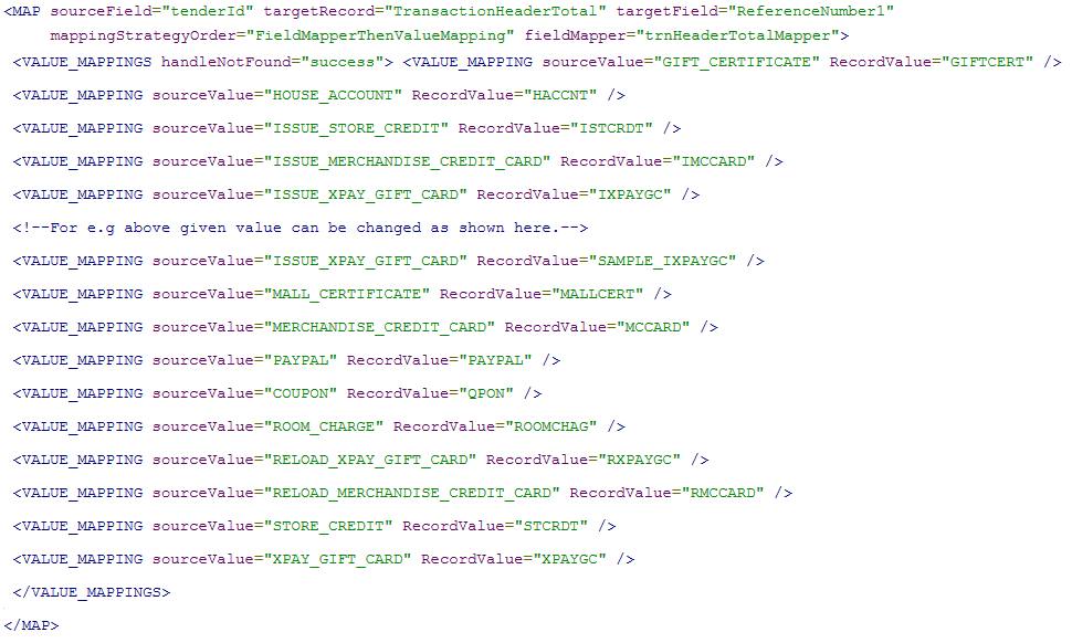
FieldMapperThenValueMapping: The RecordValue attribute values as shown in the following example can be changed:
<MAP sourceField="tenderId" targetRecord="TransactionHeaderTotal" targetField="ReferenceNumber1" mappingStrategyOrder="FieldMapperThenValueMapping" fieldMapper="trnHeaderTotalMapper">
 <VALUE_MAPPINGS handleNotFound="success"> <VALUE_MAPPING sourceValue="GIFT_CERTIFICATE" RecordValue="GIFTCERT" />
 <VALUE_MAPPING sourceValue="HOUSE_ACCOUNT" RecordValue="HACCNT" />
 <VALUE_MAPPING sourceValue="ISSUE_STORE_CREDIT" RecordValue="ISTCRDT" />
 <VALUE_MAPPING sourceValue="ISSUE_MERCHANDISE_CREDIT_CARD" RecordValue="IMCCARD" />
 <VALUE_MAPPING sourceValue="ISSUE_XPAY_GIFT_CARD" RecordValue="IXPAYGC" />
 <!--For e.g above given value can be changed as shown here.-->
 <VALUE_MAPPING sourceValue="ISSUE_XPAY_GIFT_CARD" RecordValue="SAMPLE_IXPAYGC" />
 <VALUE_MAPPING sourceValue="MALL_CERTIFICATE" RecordValue="MALLCERT" />
 <VALUE_MAPPING sourceValue="MERCHANDISE_CREDIT_CARD" RecordValue="MCCARD" />
 <VALUE_MAPPING sourceValue="PAYPAL" RecordValue="PAYPAL" />
 <VALUE_MAPPING sourceValue="COUPON" RecordValue="QPON" />
 <VALUE_MAPPING sourceValue="ROOM_CHARGE" RecordValue="ROOMCHAG" />
 <VALUE_MAPPING sourceValue="RELOAD_XPAY_GIFT_CARD" RecordValue="RXPAYGC" />
 <VALUE_MAPPING sourceValue="RELOAD_MERCHANDISE_CREDIT_CARD" RecordValue="RMCCARD" />
 <VALUE_MAPPING sourceValue="STORE_CREDIT" RecordValue="STCRDT" />
 <VALUE_MAPPING sourceValue="XPAY_GIFT_CARD" RecordValue="XPAYGC" />
 </VALUE_MAPPINGS>
</MAP>
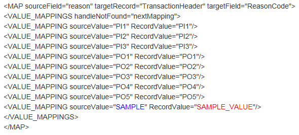
No mappingStrategyOrder and fieldMapper attributes are defined: The RecordValue attribute values shown in the following example can be changed or a new value can be added:
<MAP sourceField="reason" targetRecord="TransactionHeader" targetField="ReasonCode">
 <VALUE_MAPPINGS handleNotFound="nextMapping">
 <VALUE_MAPPING sourceValue="PI1" RecordValue="PI1"/>
 <VALUE_MAPPING sourceValue="PI2" RecordValue="PI2"/>
 <VALUE_MAPPING sourceValue="PI3" RecordValue="PI3"/>
 <VALUE_MAPPING sourceValue="PO1" RecordValue="PO1"/>
 <VALUE_MAPPING sourceValue="PO2" RecordValue="PO2"/>
 <VALUE_MAPPING sourceValue="PO3" RecordValue="PO3"/>
 <VALUE_MAPPING sourceValue="PO4" RecordValue="PO4"/>
 <VALUE_MAPPING sourceValue="PO5" RecordValue="PO5"/>
<VALUE_MAPPING sourceValue="SAMPLE" RecordValue="SAMPLE_VALUE"/>
 </VALUE_MAPPINGS>
 </MAP>
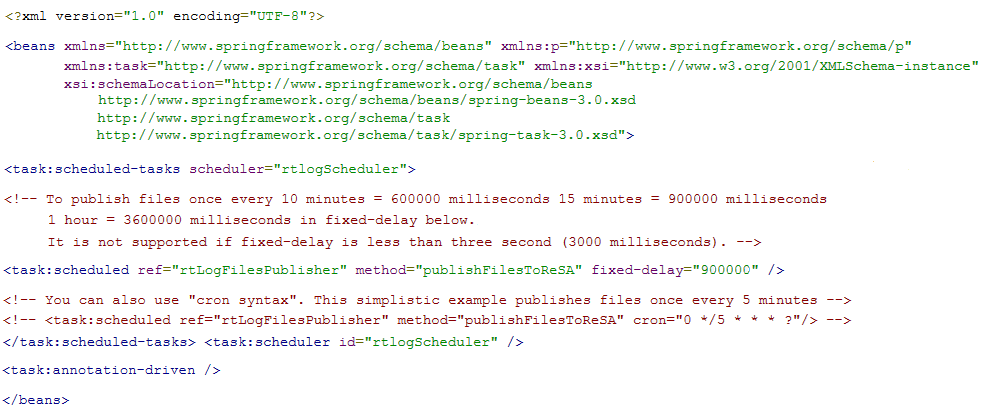
spring-scheduler.xml:
It is the most commonly modified file in the RTLog Generator application. It is used to configure the scheduled interval for publishing the RTLog files. In the case of trickle polling, the default interval should be 15 minutes, however, keeping a larger interval (at least greater than or equal to 15 minutes) is recommended as configuring with a smaller interval might affect the performance.
If you are deploying in a cluster, first set up a WebLogic cluster. For more information, see "WebLogic Cluster Setup".
This section covers the deployment in both a clustered and non-clustered environment.
To deploy the RTLog Generator application:
Log in to the WebLogic 12 Server Administration Console (http://<hostName>:<port>/console).
Click the Deployment link from the left navigation menu.
Click Install.
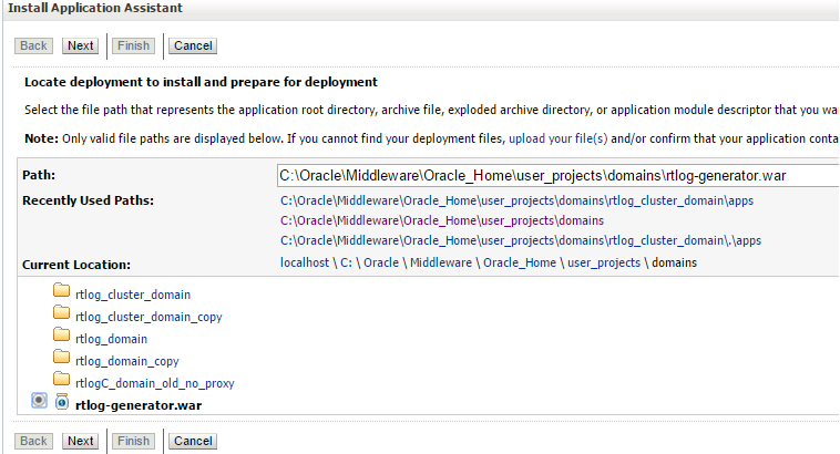
Navigate to the rtlog-generator.war file directory. Select the rtlog-generator.war option.
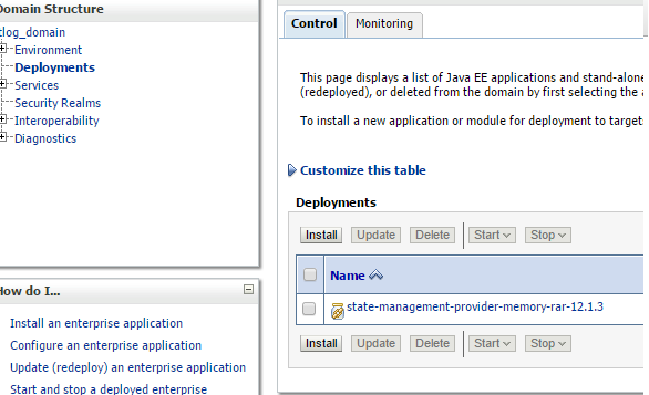
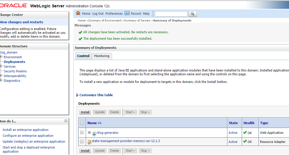
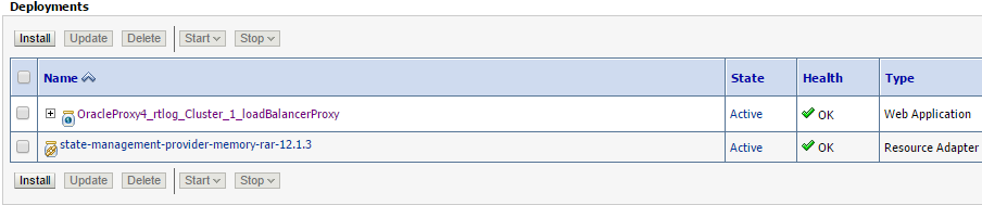
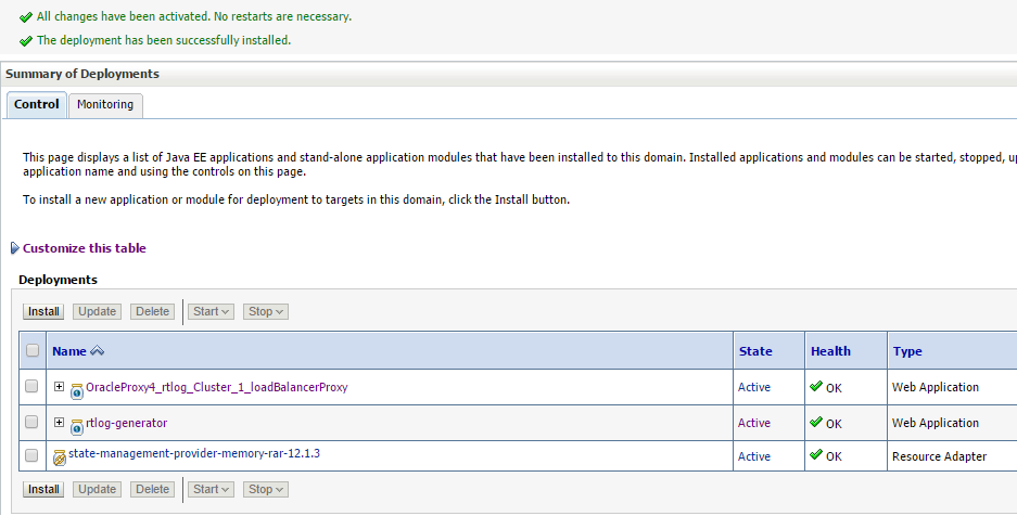
Click Next and then Finish. Once deployed, RTLog Generator should be listed as one of the deployed applications as shown in Figure 6-9.
Once the deployment is complete, following are the next steps:
To deploy on a cluster, see "Deployment of the RTLog Generator Application on a Cluster".
To enable security for the RTLog Generator application, see "Security Configuration". When deploying in a non-clustered environment, continue at this section.
|
Note: WebLogic 12c must be installed on all the clustered machines and the exact same installed directory location must be used on all the machines. |
To set up the cluster to use RTLog Generator:
Start the WebLogic configuration wizard on one machine where the Administration server needs to reside.
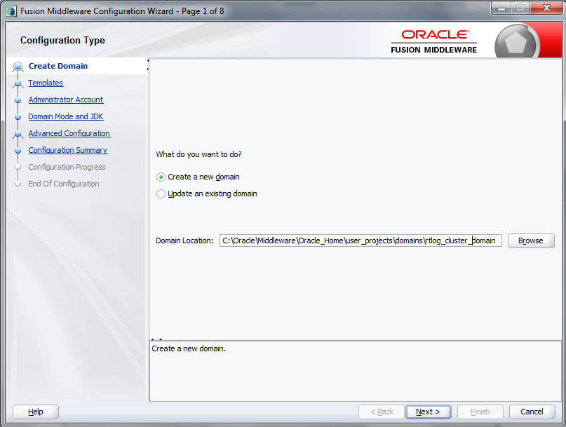
On the Configuration Wizard Configuration Type page, select Create a new domain. Enter or browse to the location for the domain. Click Next.
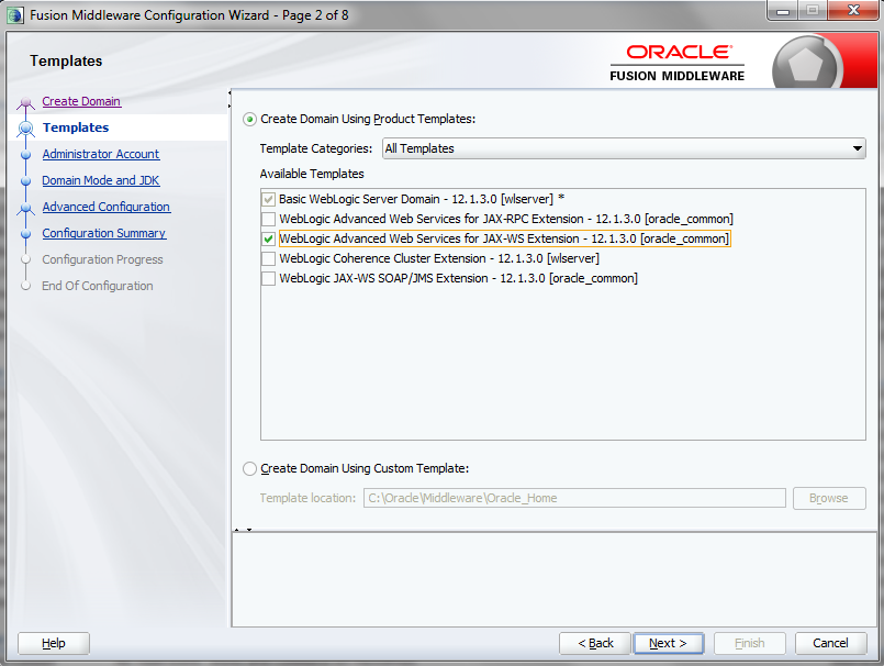
On the Templates page, select the supported products and click Next. It is recommended to select the following:
WebLogic Advanced Web Services for JAX-WS Extension - 12.1.3.0 [oracle_common]
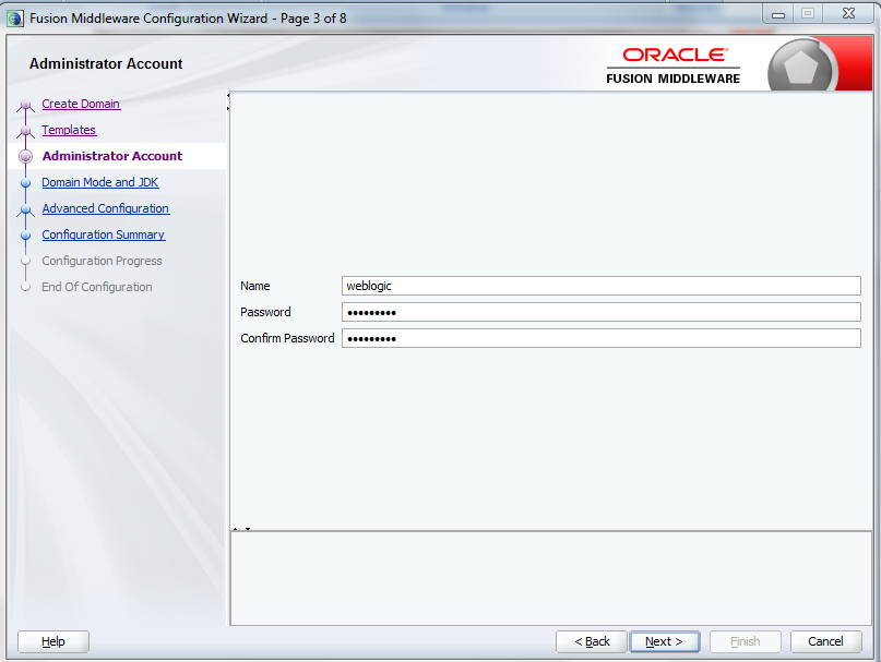
On the Administrator Account page, enter the Administrator user name and password. Enter the password a second time to confirm. Click Next.
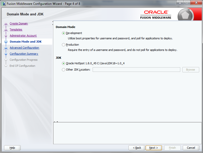
On the Domain Mode and JDK page, select either Development or Production mode. For production mode, you need to manually create the boot.properties file. Click Next.
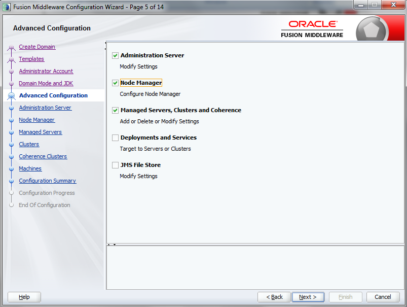
On the Advanced Configuration page, select the Administration Server, Node Manager, and Managed Servers, Clusters and Coherence options. Click Next.
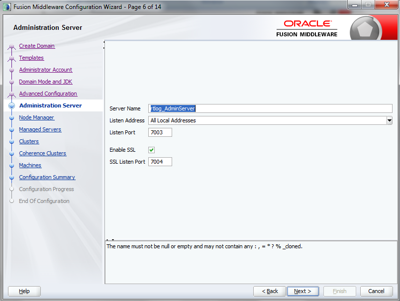
On the Administration Server page, enter the values to configure the administration server. The administrator server controls all the managed servers that are part of the cluster.
Enter the server name, select Enable SSL, and enter the listen ports. For the listen address, enter the Machine_1 IP address. Machine_1 will be part of the cluster and will have the administrator server running on it. Click Next.
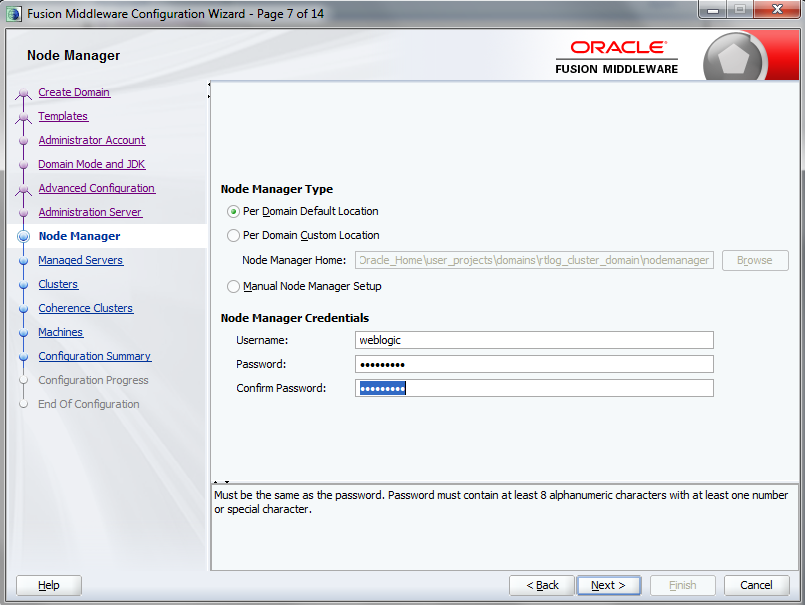
On the Node Manager page, do not change the default node manager settings. For the credentials, enter weblogic as the user name and enter the password. Click Next.
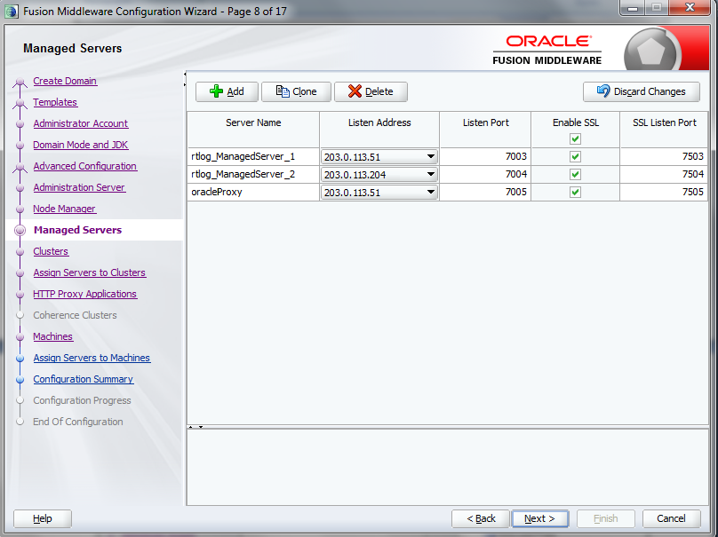
On the Managed Servers page, add and configure each managed server:
For the listen address, enter the IP address of the managed server. Do not select All local Addresses.
rtlog_ManagedServer_1 will be running on Machine_1 in this configuration. Enter the Machine_1 IP address for the server.
rtlog_ManagedServer_2 will be running on Machine_2 in this configuration. Enter the Machine_2 IP address for this server.
oracleProxy is running on Machine_1, but is not a part of the cluster. It is an Oracle proxy HTTP cluster servlet used for failover and load balancing purposes. Enter the Machine_1 IP address for this server.
Enable SSL for all the managed servers.
Click Next.
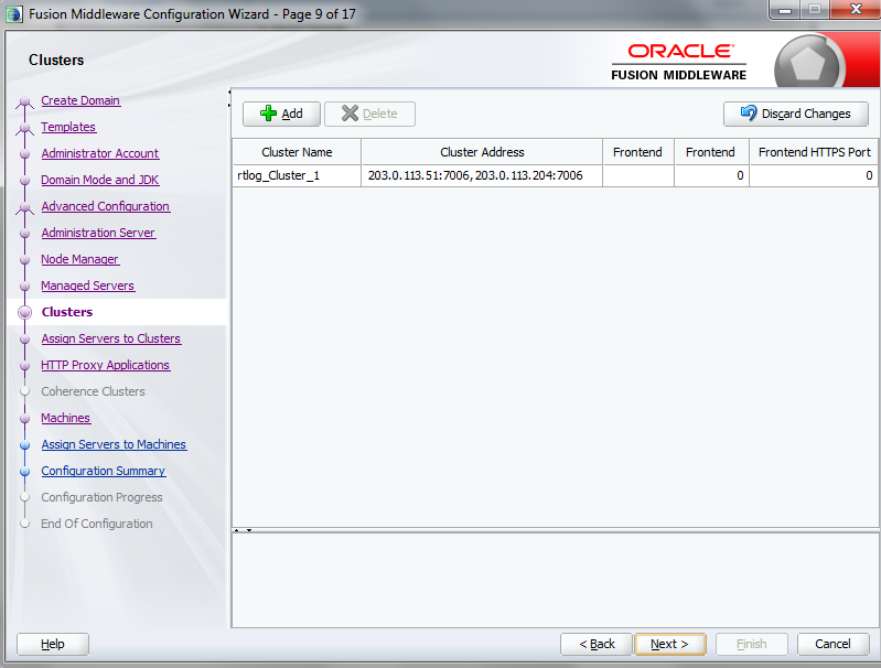
On the Clusters page, add and configure the cluster. Enter the cluster name followed by the cluster address, that is, IP address1:port1, IP address2:port2, so on. Click Next.
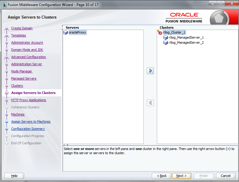
On the Assign Servers to Cluster page, assign the managed servers to the cluster. and click Next.
|
Note: Do not include the Oracle Proxy as part of the cluster. |
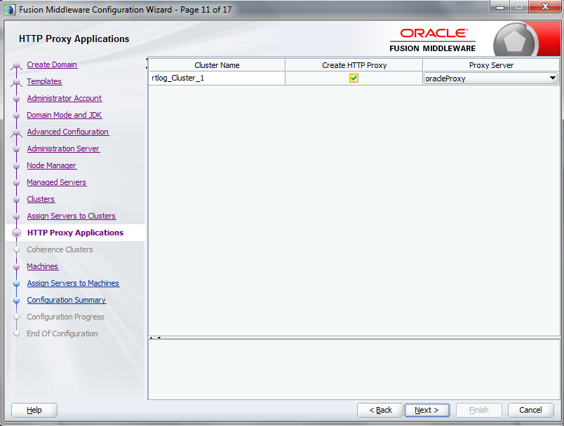
On the HTTP Proxy Applications page, select Create HTTP Proxy and then select the server from the drop-down list. By default, it should have already been selected. Click Next.
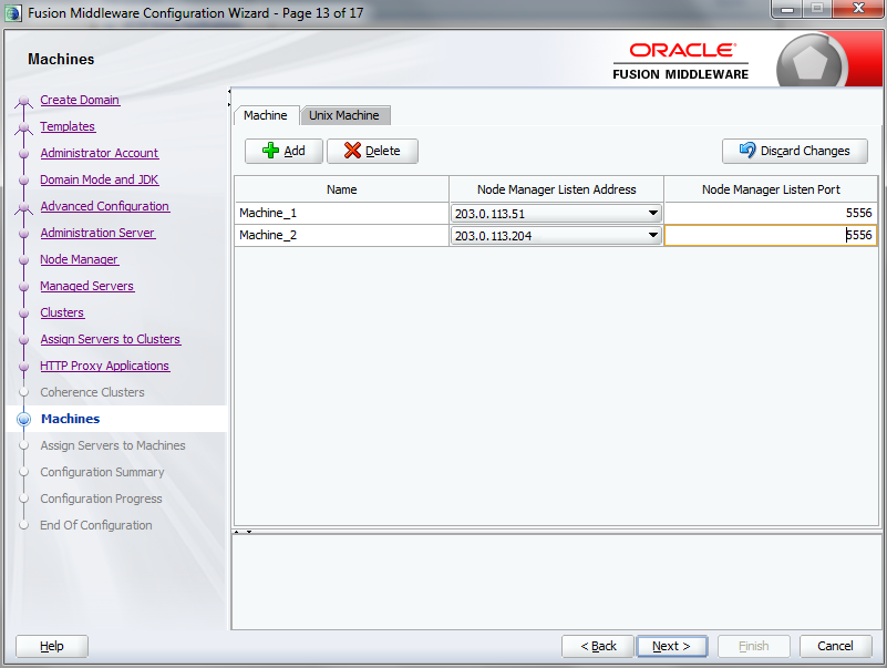
On the Machines page, add and configure each machine. To add Machine_1 and Machine_2, click Add and enter the respective IP addresses. This configuration is for setting up the Node managers on both the machines. Since these node managers are physically separated, you can select the same host. Click Next.
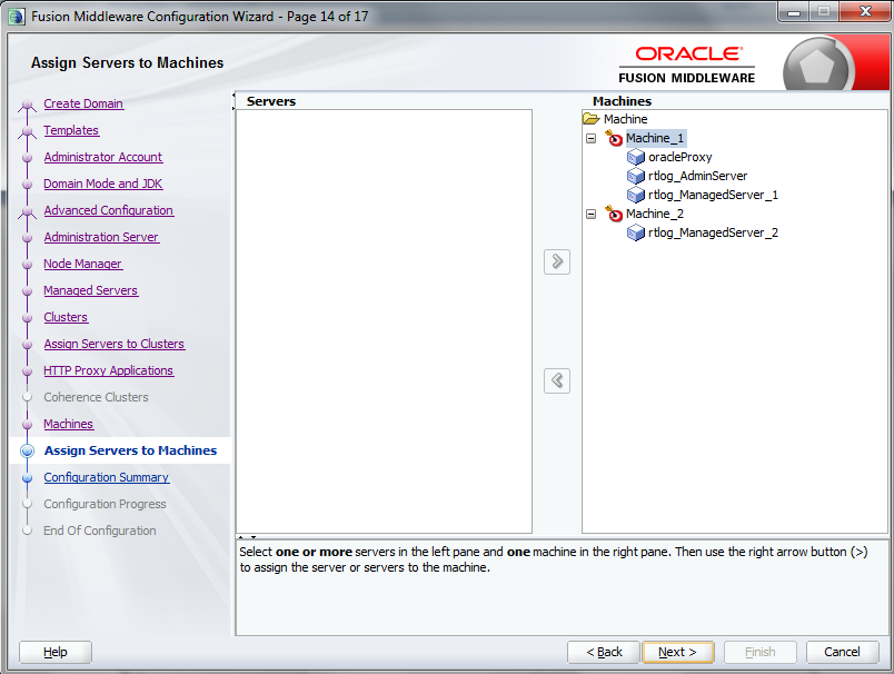
On the Assign Servers to Machines page, assign the servers to the machines. In this example, Oracle proxy (load balancer), Administration server, and one managed server are configured on Machine_1. Another managed server is configured on Machine_2. Click Next.
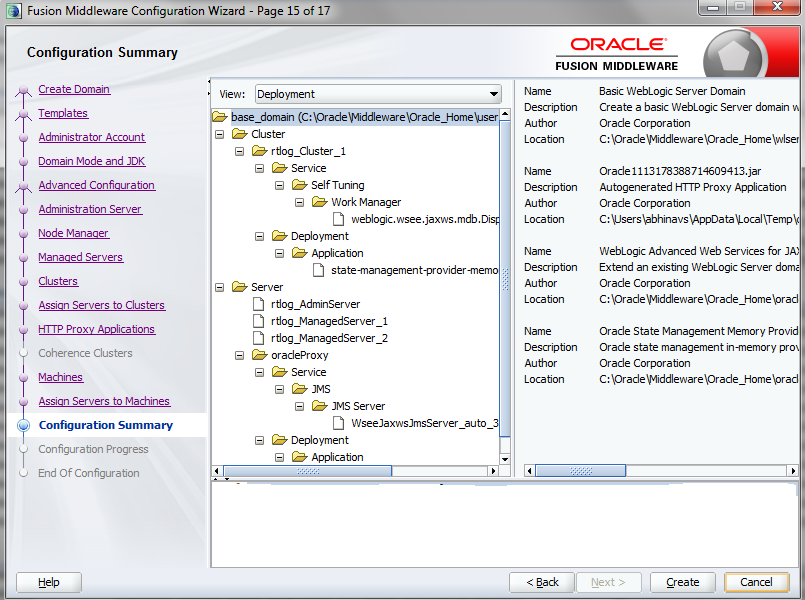
On the Configuration Summary page, verify the selected configuration. Click Create. The domain is created.
To complete the configuration of the cluster:
Start and stop the node manager. You can find the start up script inside the newly created domain, that is, the <rtlog_clust_domain>\bin directory.
In the nodemanager.properties file, set SecureListener=false. This file is found in the <rtlog_clust_domain>\nodemanager directory.
Edit the <rtlog_clust_domain>\config\config.xml file. Use plain communication for the node managers by updating the communication type for the node managers as shown in the following example:
<machine>
       <name>Machine_1</name>
       <node-manager>
      <name>Machine_1</name>
      <nm-type>Plain</nm-type>
      <listen-address>203.0.113.51</listen-address>
    </node-manager>
 </machine>
 <machine>
    <name>Machine_2</name>
    <node-manager>
      <name>Machine_2</name>
      <nm-type>Plain</nm-type>
      <listen-address>203.0.113.204</listen-address>
    </node-manager>
  </machine>
If the <rtlog_clust_domain> is created with the production mode option:
Run <rtlog_clust_domain>\startWeblogic.cmd for the first time. This creates the servers folders under the domain. Enter the administration user name and password.
Create a folder named security under the <rtlog_clust_domain>\servers\Admin server.
Create the boot.properties file with the following entries under the security folder:
password=%admin_server_password%
username=%admin_server_username%
%admin_server_password% and %admin_server_username% are the administrator password and user name.
After making these changes, if there are any running processes, shut down all the processes.
Pack the created domain:
Stop both the Node manager and Admin Server if not already stopped. Use the packing utility to pack the domain on the machine. This utility is found in the following location:
<WL_HOME>\wlserver\common\bin\pack.cmd
Run the following command:
pack.cmd -domain=<WL_HOME>\user_projects\domains\rtlog_cluster_domain -template=<WL_HOME>\user_projects\domains\rtlog_cluster_domain\rtlog_cluster_domain.jar -template_name="RTLog C domain"
This command creates a jar named rtlog_cluster_domain.jar by packing the complete domain into it. Copy the rtlog_cluster_domain.jar to Machine_2 and unpack it.
Create a <user_templates> directory on the remote machine and copy the rtlog_cluster_domain.jar file to this location. Run the following command:
unpack.cmd -template=<WL_HOME>\user_projects\domains\<user_templates>\rtlog_cluster_domain.jar -domain=<WL_HOME>\user_projects\domains\rtlog_cluster_domain
Start the Administration server and node manager on Machine_1.
To enroll the remote (Machine_2) node manager:
Run the WebLogic scripting utility. This utility can be found at the following location: <WL_HOME>\wlserver\common\bin\as wlst.cmd
Start the node manager on this machine, in this example, Machine_2. The node managed must be started before connecting to the Machine_1 Admin server.
Run the following command:
connect ('adminServer_username', 'adminServer_password','t3://Machine_1_IPAddress:Admin_server_unsecured_port')
For example: connect ('weblogic','weblogic1','t3://203.0.113.51:7003')
Once the connect command shows the connection completed successfully, run the following command:
nmEnroll ('<WL_HOME>/user_projects/domains/<rtlog_cluster_domain>','<WL_HOME>/user_projects/domains/<rtlog_cluster_domain>/nodemanager')
When the command completes successfully, run exit ().
|
Note: Repeat Step 6 for all the remote machines that will be in the cluster on which managed servers will be running. This step used Machine_2 as the example. |
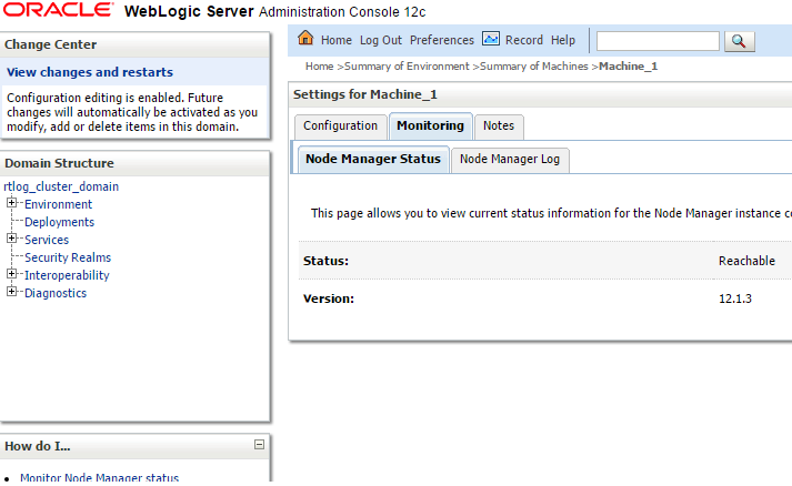
Log in to the Administration Server console and make sure all the node managers are reachable. This can be found under Machines. Repeat this step for all the clustered machines to ensure all of them are reachable.
For each managed server, select the Server Start tab. In the Arguments text box, add the following if it does not already exist:
-Xms512m -Xmx512m -XX:CompileThreshold=8000 -XX:PermSize=512m -XX:MaxPermSize=512m
If you want to configure the non-default external RTLog configuration directory, include an additional JVM argument:
-Drtloggen.config.dir=C:/<rtlog-gen-config_1>/
|
Note: The server-start arguments only work when you are using a NodeManager. If you do not have a NodeManager, specify the JVM argument in the start up scripts. You can also configure the same ext directory location in the RTLog Generator WAR's context-param. For more information, see "Configuration". |
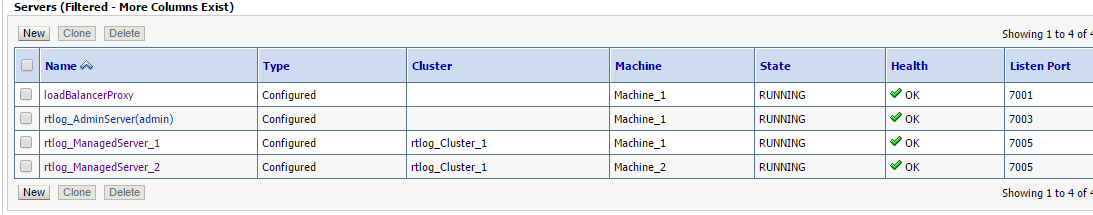
Start all the managed servers including the Oracle proxy. Figure 6-26 shows an example of the list of managed servers.
To deploy the application:
Oracle proxy creates a web application by creating the web.xml and weblogic.xml files which can be found in the following directory:
<WL_HOME>\user_projects\domains\<rtlog_cluster_domain>\apps\OracleProxy4_rtlog_Cluster_1_oracleProxy\WEB-INF
You can modify the configurations provided in these two files and redeploy the application from the console by pointing it to this directory, that is, WEB-INF.
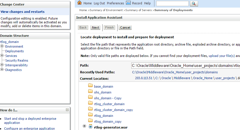
Navigate to the Administration Console home page and click Deployments in the left navigation menu. Figure 6-27 shows an example of the page before deploying the RTLog Generator application.
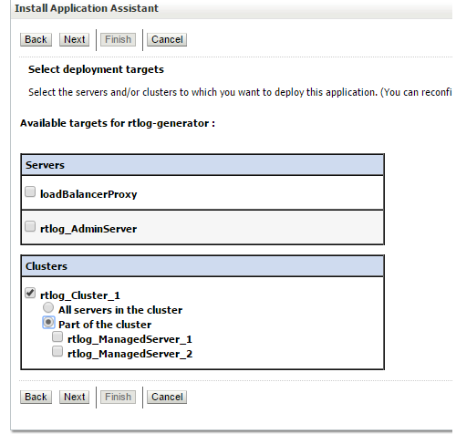
Click Install. The Install Application Assistant page appears. Select the path to the RTLog Generator WAR directory. Select the rtlog-generator.war option. Click Next.
Select only the managed servers and click Next to finish the deployment.
After it is successfully deployed, the RTLog Generator application appears in the Summary of Deployments page.
To enable container and transport level security, see "Security Configuration".
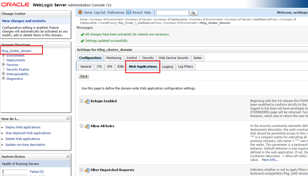
To enable the WebLogic Plugin Enabled parameter from the cluster domain:
Click the <rtlog_cluster_domain> link in the left navigation menu. Navigate to the Web Application tab.
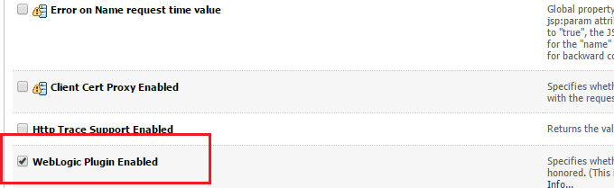
Scroll down the page and select WebLogic Plugin Enabled. Click Save.
The RTLog Generator application is secured by leveraging two levels of security:
Container level security: Basic HTTP authentication by setting up the security realm in WebLogic. To configure this security, see "Container Level Security".
Transport level security: SOAP requests are sent over the secured protocol (HTTPS) by configuring the keystore/truststore in the WebLogic domain and importing the public certificate into Xstore Office's (client) truststore. To configure this security, see "Transport Level Security".
The following steps assume that a domain has been created with secure port (HTTPS) enabled. To configure container level security:
Start the WebLogic server and log in to Administration Console.
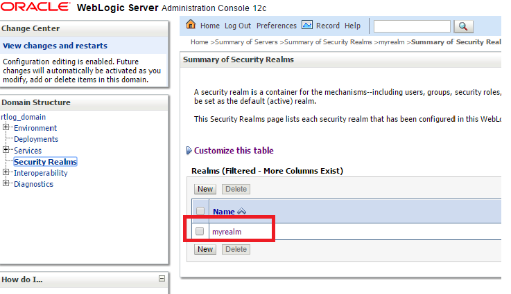
Click Security Realms in the left navigation menu.
In the list of realms on the Summary of Security Realms page, select myrealm.
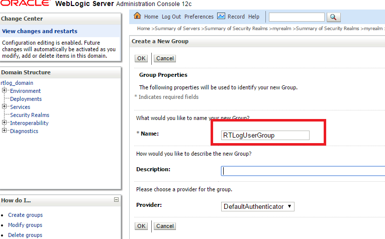
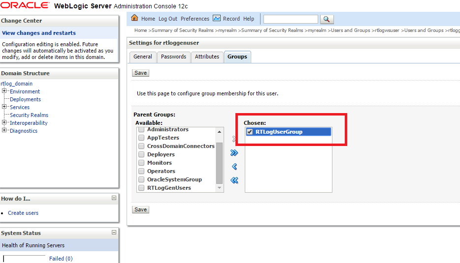
Select Users and Groups and then the Groups tab. To create a new group, click New. Enter a group name, for example RTLogUserGroup, and click OK.
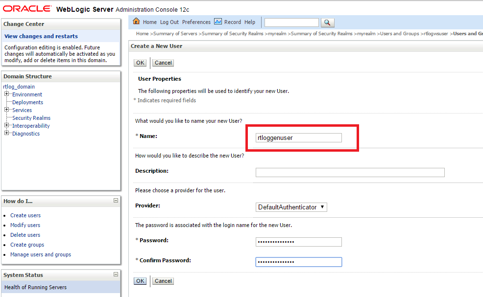
Select the Users tab and click New. Enter a user name and password and click OK.
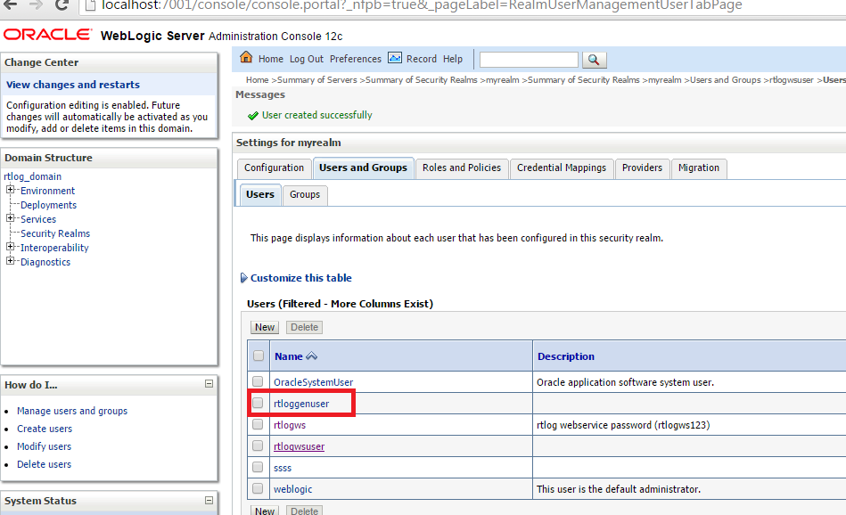
In the list of users, click the newly created user.
Select the Groups tab. Assign this user to the same group created in Step 4.
Enter the same user name and password created in Step 5 into Xstore Office's broadcaster configuration for the RTLog Generator Web service.
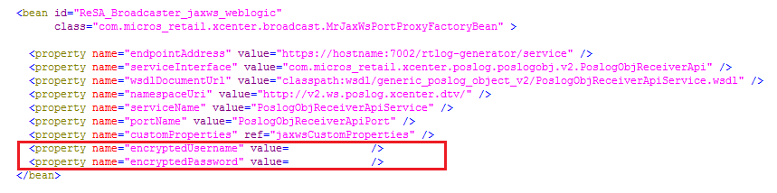
You should try the MrJaxWsPortProxyFactoryBean bean and create the encrypted values for the user name and password using the String Encryption Utility. For more information, see the Oracle Retail Xstore Point of Service Implementation Guide.
To configure transport level security:
Create keystore.jks using a keytool utility. For information on keytool utilities, see the Oracle Retail Xstore Point of Service Implementation Guide.
Export the public certificate into a truststore.jks file. These files are needed to configure the custom key and trust store for Step 3.
|
Note: In a clustered environment, import all the public certificates into one truststore file and configure all the instances of the server, including HttpClusterServlet proxy, to use the same truststore file. |
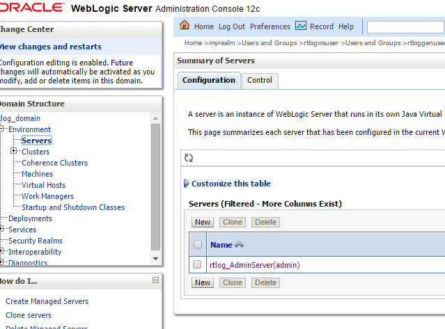
Log in to the WebLogic console. Click Environment and then the Servers link from the left navigations menu.
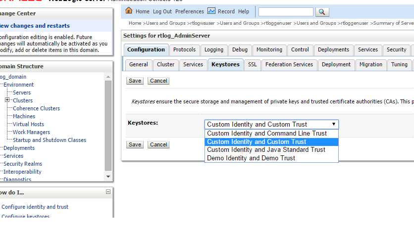
Click Change. Select Custom Identity and Custom Trust. Click Save.
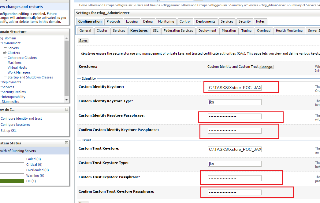
Click the linked name for the Administration Server. The page containing the settings for the Administration Server appears. Select the Keystores tab.
Enter the path to keystore.jks, including the file name, and enter the custom Identity Keystore passphrase you created for the keystore. Repeat this for trustore.jks, but enter the appropriate passphrase for the truststore. For an example, see Figure 6-41.
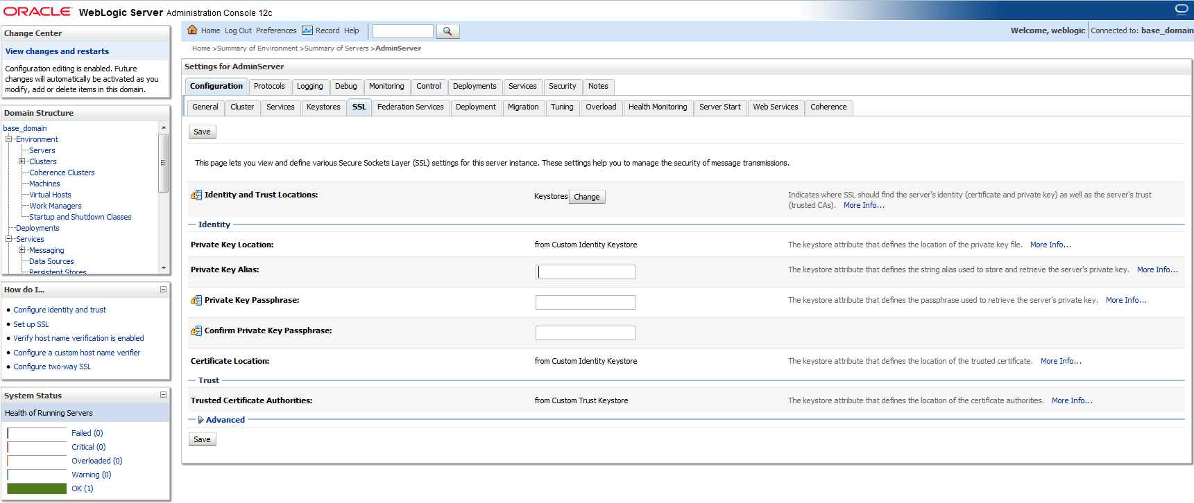
Switch to the SSL tab. Enter the alias name and private keyphrase as created during the certificate generation. To save the changes, click Save.
|
Note: For a clustered environment, disable the non-SSL port for the HttpClusterServlet proxy. |
Test both the container and transport level security using SOAPUI.
To set up the unlimited strength JCE files:
Download and install the correct version of the unlimited strength JCE files. For more information, see the Oracle Retail Xstore Point of Service Implementation Guide.
Configure WebLogic 12c with the Xstore suite of product's supported cipher suites. To configure it, update the <domain>\<domain_name>\config\config.xml file and add the following inside the ssl block:
<ciphersuite>TLS_RSA_WITH_AES_256_CBC_SHA</ciphersuite>
<ciphersuite>TLS_RSA_WITH_AES_256_CBC_SHA</ciphersuite
<ciphersuite>TLS_RSA_WITH_AES_256_CBC_SHA256</ciphersuite>
<ciphersuite>TLS_ECDHE_RSA_WITH_AES_256_CBC_SHA</ciphersuite>
<ciphersuite>TLS_ECDHE_ECDSA_WITH_AES_256_CBC_SHA</ciphersuite>
<ciphersuite>TLS_ECDHE_RSA_WITH_AES_256_CBC_SHA384</ciphersuite>
<ciphersuite>TLS_ECDHE_ECDSA_WITH_AES_256_CBC_SHA384</ciphersuite>
Disable the schema validation in WebLogic by passing the JVM argument in the WebLogic startup script:
-Dweblogic.configuration.schemaValidationEnabled=false
Xstore Office's RTLog Generator broadcaster end point should be configured to use the secured (HTTPS) URL for configuring the container level security section:
<property name="endpointAddress" value="https://<hostname>:7002/rtlog-generator/service" />
The endpoingAddress property is defined at xcenter-spring-beans.xml under Xcenter external configuration directory\xcenter-config. There are two required modifications:
Modify broadcasterManager bean in the file by uncommenting the line below.
<ref bean="ReSA_Broadcaster"/>
Configure endpointAddress of the ReSA_Broadcaster_jaxws bean.