Defining the Network
Most parameters used to define the BEA TUXEDO System network are
in the *NETWORK section, but there are some important
ones in *RESOURCES and *MACHINES.
For a networked configuration, MODEL must be
MP.
This ensures that a multiprocessor bulletin board
(including a DBBL) is established.
It also ensures that the *NETWORK section is read
by
tmloadcf
and
tmboot.
The DBBL has a separate copy of the bulletin board
structures in its process space.
The bulletin board
structures are propagated to the shared memory segment
specified in IPCKEY on the master processor and to the
derived shared memory segments on all non-master processors
participating in the application.
The MODEL parameter is also
related to the libraries with which application servers are built.
The
buildserver
command has an option that lets you specify whether
SHM
or
MP
libraries, or both, are to be link edited with the server object
file.
If both libraries are specified, you can change the MODEL
parameter without having to relink application servers.
The
LAN
option must be specified.
MIGRATE
may be specified.
MASTER is a required parameter even if MODEL is
SHM.
It takes one, or optionally two, LMID value(s),
which must be among those specified in
the *MACHINES section.
The first LMID identifies the
master processor for the configuration (and we'll get to
the implications of that in a minute).
The second LMID identifies
a processor that will be the backup to the master.
The terminology is important for understanding the way some
of the tmadmin commands work.
The following terms have very specific meanings:
You will find these terms used in
the section of Chapter 8,
The Use of tmadmin(1)
called ``Handling a Partitioned Network.''
The processor designated as the master is the one on which
tmloadcf
must be executed to store the TUXCONFIG file.
It is also the processor from which
tmboot
must be executed to start the application.
When the term ``non-master'' is used in this guide
it refers to all machines in the configuration
other than the master.
If, while the application is running, the master processor
loses the virtual circuit to other processors, the System/T
administrator can login to the
ACTING BACKUP and execute
the
tmadmin master
command.
This causes the
ACTING BACKUP to become the ACTING MASTER
and the DBBL to be brought up on it.
The application can continue to run
(although possibly in a degraded state).
There is more on this in Chapter 8.
There are three parameters in the *MACHINES section that
have special significance for System/T networks.
The TYPE parameter is used to group entries in the
*MACHINES section into families.
Machines are considered to be in the same family if they
share the same data representation scheme; that is, the
same data size, byte ordering, floating
point format and structure alignment.
This extends to the compilers used on different
machines; if your application has a network of identical
machines, but you build executables with different
compilers, you may well have different data
representation within executables and you should use the
TYPE
parameter to force messages to go through data
conversion routines.
If all the machines on your network
have the same data representation scheme, nothing is gained
by specifying a TYPE.
The benefit comes when you have a heterogeneous network,
that is, when one or more of your machines uses a
different scheme of data representation.
To illustrate, if you have a network of ten machines, nine of
which have the same data representation scheme,
you can assign a TYPE parameter to the
odd machine and omit the parameter for the other nine.
That way, messages to or from the tenth machine go through
data conversion routines.
Messages between the other nine do not.
The ULOGPFX parameter is used to give a pathname and prefix
for the file where messages are sent by
userlog(3c).
In addition to being available for use in
application-written code, the
userlog( )
function is used by BEA TUXEDO System software for error, warning and
information messages.
If the parameter is not specified, the default is the value
of the required APPDIR parameter plus the
prefix ULOG.
See
userlog(3c) for a description of the format of log
messages.
If remote file sharing (RFS of NFS)
is present on your network,
you might find it useful
to direct all ULOG messages to a single file--probably
located on the master node.
Here are the BEA TUXEDO System specifications to set that up:
For information on establishing a domain for your System/T
application,
see the documentation for
RFS
or
NFS
in the Administrator's Guide
for your operating system software.
The
ENVFILE
parameter can be set to the pathname of a file that
contains variables that are added to the environment for
all servers on the machine.
CMPLIMIT
can be used to specify whether or not data compression
should be used on messages; it applies to all System/T messages
as well as application messages.
If the decision is that messages should be compressed,
CMPLIMIT
can be used to specify size thresholds for both remote
and local messages.
The syntax of the variable is:
An environment variable,
TMCMPPRFM,
can be used to set the level of compression.
This variable adds further control to data compression by allowing you
to go beyond the simple choice of "compress or don't compress" that is
provided by CMPLIMITand specify any of nine levels of
compression.
TMCMPPRFM takes as its value a single digit in the range of
1-9.
A value of 1 specifies the lowest level of compression, 9 is the
highest. When a low number is specified, the compression routine does
its work more quickly.
(See
environment(5)
for details)
Data compression is
useful in most applications and is in fact vital to supporting large
configurations.
Following is a list of recommendations for when
to use data compression and for how the limits should be set.
When should I set remote data compression and what setting
should be used ?
You should always use remote data compression as long as
all of your sites are Release 4.2.1 or later.
The setting used depends on the speed of your network.
In general,
we can separate the decision into high-speed
(for example, ethernet) and low-speed (for example, X.25) networks.
High-speed network - Set remote data compression to
the lowest limit for System/T generated file transfers
(see note below on file transfers),
that is, compress only messages
that are large enough to be candidates for file transfer
either on the sending site or the receiving site.
Note that each machine in an application may have a different
limit and the lowest should be chosen.
Low-speed network - Set remote data compression to 0 on
all machines; that is, compress all application and system
messages.
When should I set local data compression and what setting
should be used ?
You should always set local data compression for Release 4.2.1
or later sites even if they are interoperating with pre-4.2.1
sites.
The setting should be the local limit for System/T
generated file transfers (see note below).
This avoids file transfers in many cases that might otherwise have
required one and greatly reduces the size of files used
if file transfers are still necessary.
EXCEPTION:
High traffic applications that experience
a large volume of timeouts and discarding of messages due
to queue blocking may want to set local compression to always
occur, thus lowering the demand of the application on the
queuing subsystem.
Note:
BEA TUXEDO System transfers application and system
messages via a file transfer mechanism if they exceed 3/4 the
maximum size of an individual message queue
(MSGMNB)
on the local system.
This is a key threshold since generating a file transfer places
a large processing burden on the local processor.
In many cases
data compression can be used to avoid file transfers that might
have otherwise been necessary.
All machines in a network must have
BEA TUXEDO System Release 4.2.1 or later
installed if compression is used.
Applications running on nodes with earlier releases
do not have the ability to decompress messages.
The
NETLOAD
environment variable affects the
load balancing behavior of a system when a service
is available on both local and remote machines.
NETLOAD
is a numeric value (of arbitrary units)
that is added to the load factor of services remote
from the invoking client.
This provides a bias for
choosing a local server over a remote one, a sensible
preference since network communication involves
overhead and delay.
As an example, assume servers A and B offer a
service with load factor 50.
A is running on
the same machine as the calling client (local),
and B is on a different machine (remote).
If
NETLOAD
is set to 100, approximately
three requests will be sent to A for every one
sent to B.
Another load balancing enhancement
that came in Release 4.2.1
is local idle server preference.
Requests are
preferentially sent to a server on the same machine
as the client, assuming it offers the desired service
and is idle.
This decision overrides any load balancing
considerations, since the local server is known to
be immediately available.
SPINCOUNT determines
the number of times a process will try to get
the shared memory latch before going to sleep.
Setting this to a value greater than one on a multiprocessor gives the
process holding the latch time to finish up with it.
On a uniprocessor this value is best left at 1.
On a multiprocessor, an initial value of 5000 should be tried,
with further tuning to find an optimal value.
The general form for entries in this section is:
Required parameters are:
Optional parameters are:
Note: In Release 6.4, parallel data circuits are
prioritized by network group number (NETGRPNO) within
priority group number. In future releases, a different algorithm
may be used to prioritize parallel data circuits.
The *NETGROUPS Section must come before the *NETWORK Section
in the configuration file.
If it comes after it, tmloadcf(1)
has a fit.
The *NETWORK section is used to identify the machines
that participate in the network and,
if you are using a TLI-based network,
to give the location of the network via the
BRIDGE parameter.
Network
devices are used by the System/T software
for communication across a TLI network.
The Sockets-based network instantiation
does not use the information in the BRIDGE
parameter.
The parameters of the *NETWORK section permit you to
specify any network provider supported by the
network dependent library specified when the BEA TUXEDO System software
is built.
Examples in this chapter illustrate the specifications for
a
STARLAN
network or a
TCP/IP
network; other supported networks can be defined using
the addressing scheme specific to them.
Beginning with Release 6.4, a machine (LMID) can be in any number of
network groups.
Every LMID must be a member of DEFAULTNET.
*NETWORK section entries have the following form:
an LMID can be specified more than once; that is how a logical
machine can be associated with more than one network group.
There are the following parameters:
NADDR (required) is the unique address within the
application network used by remote nodes to contact the
bridge process of the entry.
NLSADDR (required) is the address on
this node for the tlisten process.
BRIDGE (optional) identifies the device used by the
bridge process to access the network.
MINENCRYPTBITS (optional) specifies the minimum level of encryption for
a network link.
MAXENCRYPTBITS (optional) specifies the maximum level of encryption
for a network link.
NETGROUP (optional) specifies the name of the network group with
which this entry is associated.
bridge process to access the network.
The details of specifying these parameters
are given in the sections that follow.
LMID, of course, is a *MACHINES section entry
used as a tag in *NETWORK section,
but there is one consideration that you should bear in mind when
specifying *NETWORK section entries:
if the node is a multiprocessor computer, choose an LMID
that identifies
a processing element local to the network device named
in the BRIDGE parameter to minimize
bus traffic on the multiprocessor node.
The NADDR parameter is used to specify the unique
network address
(``unique,'' meaning not used by any other application)
through which remote nodes reach the BRIDGE
process on this processor.
The format of the network address can be a string of 76 hexadecimal
digits or less. If the string has the form ``0xhex-digits'' or
``\\xhex-digits'', it must contain an even number of valid hex digits.
These forms are translated internally into a character array containing
TCP/IP addresses may also be in either of the following two forms:
The "#.#.#.#" is the dotted decimal format where each #
represents a decimal number in the range 0 to 255.
Port_number is a decimal number in the range 0 to 65535.
Whichever format is used it is recommended that you enclose
the entire address string in double quotes, as for example:
NLSADDR specifies the network address of the tlisten
process on the particular LMID.
An NLSADDR parameter
is required for each entry in the *NETWORK section
(
tmloadcf(1) prints an error if NLSADDR is missing on
any entry but the MASTER LMID for which it prints a warning.
However, if NLSADDR is missing on the MASTER LMID,
tmadmin(1) will not be able to run in administrator mode
on remote machines; it will be limited to read-only operations.
This also means that the backup site will be unable to
The value for
NLSADDR
can be in any of the formats descirbed above for
NADDR,
and must match the address
specified with the
-l
option of the
tlisten
process on the same node.
The BRIDGE parameter specifies the device name used by the
bridge process to access the network.
It will likely be of the form:
When a network link is established to the machine identified by the
LMID
for the current entry, the MIN & MAX parameters are used to specify
the number of significant bits of the encryption key.
MINENCRYPTBITS
say, in effect, "at least this number of bits are meaningful."
MAXENCRYPTBITS,
on the other hand, says, "encryption should be negotiated up to
this level."
The possible values are 0, 40 and 128.
A value of 0 means no encryption is used, while 40 and
128 specify the number of significant bits in the encryption
key.
These two parameters are functional only if a BEA TUXEDO Security
Add-on Package is installed.
The U.S. package permits use of up to 128 bits; the International
package can not specify more than 40 bits.
The configuration example shown in Figure 1 is taken from the
bankapp application.
It shows the *NETWORK section of the
application before the addresses and device names
specific to the application have been substituted.
It's typical of a *NETWORK Section from the time when the
BRIDGE parameter was required.
Figure 3 shows the configuration parameters required to
implement the design diagrammed in Figure 2.
Two new terms, Failover and Failback, have been added to the
BEA TUXEDO Glossary
because they describe how the R6.4 BRIDGE process works.
Both of the terms apply when an
LMID
is a member of more than
one Network Group.
When more than one
NADDR
is specified for an
LMID,
the system sorts the entries in order of priority.
When a message is sent, the BRIDGE process
establishes the connection on the highest
priority circuit available.
If a circuit failure occurs, message traffic is
automatically transferred to the circuit with the
next highest priority.
This seamless transfer of message traffic is called "Failover."
When message traffic is flowing over a lower priority circuit,
the BRIDGE process continually checks for an available circuit
of a higher priority.
When one is available, traffic is automatically transferred to that
circuit.
That transfer is called "Failback."
*RESOURCES Section Parameters
MODEL
OPTIONS
MASTER
The *MACHINES Section
TYPE
ULOGPFX
ULOGPFX=/tuxapp/ULOG
ULOGPFX=/mnt/mach1/tuxapp/ULOG
where /mnt is the
RFS
or
NFS
mount directory.
ENVFILE
CMPLIMIT
CMPLIMIT=[remote_threshold[,local_threshold]]
The
threshold
value can be a number from 0 to
MAXLONG.
(MAXLONG
is automatically translated to the value appropriate for
the host processor.)
The meaning of the number is that any message greater
than or equal to
threshold
should be compressed, so that:
CMPLIMIT=0,MAXLONG
says that messages moving over the network are always compressed and
local messages are never compressed.
The default for each threshold is ``never,''
so the above specification could have been simply:
CMPLIMIT=0
A specification of:
CMPLIMIT=1024
means that remote messages of 1024 bytes or more (including the
message header) are compressed; remote messages below that
limit and all local messages are not.
Setting the Compression Level
Taking Advantage of Data Compression
Data Compression Limitations
NETLOAD
SPINCOUNT
The *NETGROUPS Section
The *NETGROUPS Section describes network groups available to the
application.
NETGROUP required parameters [optional parameters]
where NETGROUP is the name the application uses to refer
to this group.
NETGROUP takes a string value of up to 30 characters.
The value DEFAULTNET
has a special meaning; it is used to describe the
default network group, which is the same as saying the
network of all the machines in the application.
NETGRPNO = numeric_value
This is a unique network group number assigned by the administrator.
If the group is DEFAULTNET then NETGRPNO
must have a value of 0 (zero).
NETPRIO = numeric_value
Specifies the priority for this network group.
The value must between 1 and 8,192; the default is 100.
A pair of machines in multiple network groups of the same
priority communicates simultaneously over the circuits with
the highest priority.
If all network circuits of a certain priority are torn down
by the administrator or by network conditions, the next lowest
priority circuit is used.
Retries of the higher priority circuits are attempted.
The *NETWORK Section
*NETWORK Section Entries
LMID parameters
where LMID is one of the logical machine identifiers
specified in the *MACHINES section.
LMID
NADDR
"//hostname:port_number"
"//#.#.#.#:port_number"
In the first of these formats, hostname is resolved to a TCP/IP
host address at the time the address is bound using the locally
configured name resolution facilities accessed via
gethostbyname(3c).
NADDR="mach1.acme.com:65432"
If the hex digit format is used,
you precede the digits with
a ``0x'' (zero x) as in:
NADDR="0x0020401c00b6d05"
NLSADDR
BRIDGE
MINENCRYPTBITS/MAXENCRYPTBITS
NETGROUP
The
NETGROUP
parameter takes a string of up to 30 characters.
The string must be one of
the network group names previously specified in the *NETGROUPS
section.
The
NETGROUP
parameter identifies the
LMID
associated with this entry as being a member of the named network
group.
If the parameter is not specified,
the machine identified by this entry is
assumed to be served only by
DEFAULTNET.
Configuration Example
Figure 1: *NETWORK section, bankapp
#
*NETWORK
		# Substitute values appropriate for your application
		# for items enclosed in angle brackets < >
SITE1	NADDR="<network address of SITE1>"
	BRIDGE="<device of provider>"
	NLSADDR="<network listener address of SITE1>"
SITE2	NADDR="<network address of SITE2>"
	BRIDGE="<device of provider>"
	NLSADDR="<network listener address of SITE2>"
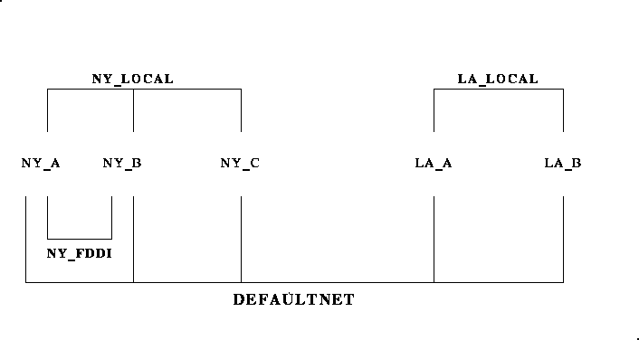
Figure 2 is a diagram showing groups of networks that can be defined
using Release 6.4 configuration parameters. The application in this
example has five logical machines (LMIDSs), grouped into four Network
Groups (NETGROUPS).
Each LMID belongs to a minimum of two, and a maximum of three,
NETGROUPS.
Sample Network Diagram
NETGROUPS and NETWORK Section Parameters for the Enhanced BRIDGE
#
*NETGROUPS
DEFAULTNET		NETGRPNO=0		NETPRIO=100 #default
BLUE_GROUP		NETGRPNO=9		NETPRIO=100
MAGENTA_GROUP	NETGRPNO=125	NETPRIO=200
GREEN_GROUP		NETGRPNO=13		NETPRIO=200
#
*NETWORK
#LMID: LA_A
A	NETGROUP=DEFAULTNET	NADDR="//A_CORPORATE:5723"
A	NETGROUP=MAGENTA_GROUP  NADDR="//A_MAGENTA:5724"
A	NETGROUP=GREEN_GROUP  	NADDR="//A_GREEN:5725"

B	NETGROUP=DEFAULTNET	NADDR="//B_CORPORATE:5723"
B	NETGROUP=MAGENTA_GROUP  NADDR="//B_MAGENTA:5724"
B	NETGROUP=GREEN_GROUP  	NADDR="//B_GREEN:5725"

C	NETGROUP=DEFAULTNET	NADDR="//C_CORPORATE:5723"
C	NETGROUP=MAGENTA_GROUP  NADDR="//C_MAGENTA:5724"

D	NETGROUP=DEFAULTNET	NADDR="//D_CORPORATE:5723"
D	NETGROUP=BLUE_GROUP 	NADDR="//D_BLUE:5726"

E	NETGROUP=DEFAULTNET	NADDR="//E_CORPORATE:5723"
E	NETGROUP=BLUE_GROUP  NADDR="//E_BLUE:5726"
Network Administration
For releases prior to Release 6.4,
the BEA TUXEDO BRIDGE process allows only a single
NADDR
per
LMID
and provides virtual one-hop connections between any pair of
nodes defined for an application.
The R6.4 BRIDGE supports the definition of network groups,
manages multiple listening addresses per node and virtual
circuits among netgroups, while continuing to support the
same virtual one-hop network of prior releases.
In R6.4, the highest priority circuits flow data in parallel.
In the event of network virtual circuit failure, the next available
address and virtual circuit is used.
When circuits fail, periodically the higher priority circuit attempts
to reconnect while data continues to flow over the lower priority
circuit.
How BEA TUXEDO Detects Network Failures
The BEA TUXEDO System relies on the underlying operating system for
information about network failures.
When a failure is reported, BEA TUXEDO writes a message to the
userlog.
One difficulty with this reliance on the operating system is
that it almost never includes any information about what messages
may have been successfully transmitted before the failure.
Another is that there may be some delay before BEA TUXEDO is
informed, and idle connections may not be checked.
How to Change Network Parameters
This section will be based on changes that
have been made in the software, but are not
yet documented in the tmconfig(1) man page.
How to Ensure Correct Message Sequence
This is mainly a programming change for the application (assuming that
sequencing of Request/Response messages is important to them)
to control the flow of messages, but there are one or two things an
Administrator can do to help the situation, including a kind of a
stop-gap measure that can be used before the application is
re-written.