2 Configuring the OracleAS CDC Adapter for DB2
This chapter describes how to configure Oracle Connect using Oracle Studio.
All modeling of Oracle Connect is performed using Oracle Studio. To use Oracle Studio, you first configure it to enable access to the z/OS platform with the DB2 data.
Note:
The following tasks assume you have permission to access the IBM z/OS platform and that the Oracle Connect daemon is running on this computer.Check with the system administrator to ensure these requirements are fulfilled.
This chapter includes the following topics:
Setting Up the IBM z/OS Platform in Oracle Studio
Using Oracle Studio, perform the following steps to configure the IBM z/OS platform:
-
From the Start menu, select Programs, Oracle, and then select Studio. Oracle Studio opens, displaying the Design perspective.
-
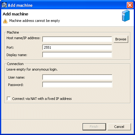
Right-click Machines in the Configuration Explorer and select Add Machine. The Add Machine screen is displayed.
-
Enter the name of the computer you want to connect to, or click Browse to select the computer from the list of computers that is displayed and which use the default port (2551).
-
Specify the user name and password of the user who was specified as the administrator when Oracle Connect was installed.
Note:
Selecting Anonymous connection enables anyone having access to the computer to be an administrator, if this was defined for the computer. -
Click Finish.
The computer is displayed in the Configuration Explorer.
Securing Access to Oracle Connect
Oracle Studio includes mechanisms to secure access to Oracle Connect both during modeling and at run time.
During modeling, the following security mechanisms can be applied:
At run time client access to Oracle Connect is provided by the user profile:
Setting Password Access to Oracle Studio
Initially, any operation performed using Oracle Studio does not require a password. You can set a password so that the first operation that involves accessing the server from Oracle Studio requires a password to be entered.
Perform the following steps to set password access to Oracle Studio:
-
From the Start menu, select, Programs, Oracle, and then select Studio. Oracle Studio opens.
-
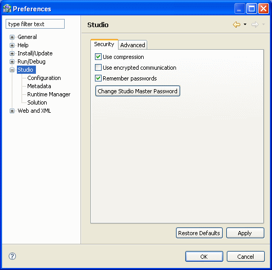
Select Window from the menu bar, and then select Preferences. The Preferences screen is displayed.
-
Click Studio in the left pane as shown in the following figure:
-
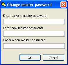
Click Change Studio Master Password. The Change Master Password screen is displayed, as shown in the following figure:
-
Leave the Enter current master password field blank and type a new master password in the Enter new master password field.
-
Enter the new passoword again in the Confirm new master password field.
-
Click OK.
Specifying Users with Administrative Rights
By default, only the user who was specified during the installation as an administrator has the authorization to modify settings on that computer from Oracle Studio. This user can then authorize other users to make changes or to view the definitions for a selected computer. Adding a computer to Oracle Studio is described in "Setting Up the IBM z/OS Platform in Oracle Studio".
Note:
The default during installation is to enable all users to be administrators.-
From the Start menu, select, Programs, Oracle, and then select Studio. Oracle Studio opens.
-
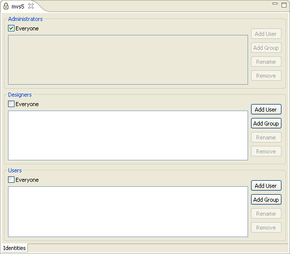
In the Design perspective Configuration view, Right-click the computer and select Administration Authorization.
The Administration Authorization screen is displayed as shown in the following figure:
The screen has the following sections:
Administrators: Administrators can view and modify all the definitions in Oracle Studio for the selected computer. On initial entry to Oracle Studio, every user is defined as a system administrator.
Designers: Designers can view all the definitions for the computer in Oracle Studio and can modify any of the definitions under the Bindings and Users nodes for the selected computer. For example, Oracle Studio database administrator can add new data sources and adapters and can change the metadata definition for a table in a data source.
Users: Users can view all the definitions for the computer in Oracle Studio for the selected computer. Regular users cannot modify any of the definitions.
-
Add users or groups of users by clicking Add User or Add Group for the relevant sections.
The user or group that is added must be recognized as a valid user or group for the computer. Once a name has been added to a section, only the user or group that logs on with that user name has the relevant authorization.
Setting Up Run-Time User Access to the IBM z/OS Platform
During run time, client access to Oracle Connect is provided by the user profile. A user profile contains name and password pairs that are used to access a computer, data source or application at run time, when anonymous access is not allowed.
-
From the Start menu, select, Programs, Oracle, and then select Studio. Oracle Studio opens.
-
From the Design perspective, Configuration view, expand the Machines folder, then expand the machine where you want to set the user name and password.
-
Expand Users.
-
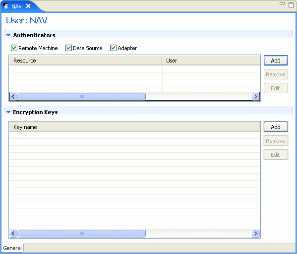
Right-click the NAV user profile and select Open. The NAV user profile editor is displayed:
-
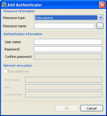
In the User editor, click Add. The Add Authenticator screen is displayed:
-
Select Remote Machine from the Resource Type list.
-
Enter the name of the z/OS computer defined in Oracle Studio.
-
Enter the name and password used to access the computer and confirm the password.
-
Click OK.
Setting Up a Change Data Capture with the OracleAS CDC Adapter for DB2
You must set up the Oracle Connect DB2 CDC adapter on the z/OS platform to handle capture changes to the DB2 data. To work with the DB2 CDC adapter, you must configure the DFSFLGX0 exit and set up the security parameters on the z/OS computer and then configure the change data capture using the Oracle Studio CDC Solution perspective. Oracle Studio must be installed on a Windows or UNIX computer.
Perform the following steps to setup the change data capture and configure the CDC adapter:
Configuring the DB2 Tables for CDC
In this task you define the data capture changes attribute on the tables where the changes are captured using the DB2 agent. You can use the following DB2 command:
ALTER TABLE <TABLE_NAME> DATA CAPTURE CHANGES;
Setting up Security for the OracleAS CDC Adapter for DB2
To work with Oracle Connect and DB2, the following requirements must be met:
-
All the libraries in the
ATTSRVRSTEPLIBmust be APF-Authorized. -
Provide the following grants to the owner of the
ATTSRVRstarted task.Command Purpose GRANT TRACEThis command grants the -start trace()privilege.GRANT MONITOR2This command grants the READAandREADS IFIrequests privilege. -
The owner of the
ATTSRVRstarted task must have privileges in DB2 to run offline.For details about setting DB2 security to use DB2 with Oracle Connect, see Oracle Application Server CDC Adapters Installation Guide.
Configuring the ATTSRVR Started Task
In the ATTSRVR started task STEPLIB, check that there is a DD card that defines the used DB2 load library (usually expressed as HLQ.SDSNLOAD).
Configure the ODBCINI file defined in the DSNAOINI DD card of the ATTSRVR started task. In most cases, you can use the default configurations in the ODBCINI file however, you can make changes to the file, if needed.
The following is an example of the ODBCINI file:
; This is a comment line...; Example COMMON odbcini COMMONMVSDEFAULTSSID=DSN1
; Example SUBSYSTEM odbcini for DSN1 subsystem DSN1MVSATTACHTYPE=CAFPLANNAME=DSNACLI
The following table describes the configurations that are important for the DB2 CDC agent.
Table 2-1 ODBCINI configuration values
| Configuration | Description |
|---|---|
|
|
The Sub-System ID (SSID) of the default used DB2 instance. |
|
|
Use the If |
|
|
The DB2 Calling Level Interface (CLI) plan name. Usually the name of the CLI plan is DSNACLI (as defined in HLQ. |
You can specify other parameters in this file, as described in the IBM ODBC Guide and Reference.
Setting up a Change Data Capture in Oracle Studio
You set up the change data capture in Oracle Studio. Oracle Studio can be installed on Windows XP or Vista operating systems, or on UNIX.
A change data capture is defined in the CDC Solution perspective, which contains a series of links to guide you through the CDC set up process. The CDC solution perspective guides display the following symbols in front of a link to show you what tasks should be done, and what tasks were completed.
-
Triangle: This indicates that there are subtasks associated with this link. When you click the link, the list expands to display the subtasks.
-
Asterisk (*): This indicates that you should click that link and perform the tasks and any subtasks presented. If multiple links have an asterisk, you can perform the marked tasks in any order.
-
Check mark (✓): This indicates that the tasks for this link and any sublink are complete. You can double click the link to edit the configuration at any time.
-
Exclamation mark (!): This indicates a potential validation error.
Perform the following to set up a change data capture:
Create a CDC Project
To create a CDC Project
-
From the Start menu, select, Programs, Oracle, and then select Studio.
-
Open the CDC Solution perspective, click the Perspective button on the perspective toolbar and select CDC Solution from the list.
The CDC Solution perspective opens with the Getting Started guide in the left pane of the workbench.
-
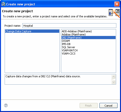
Click Create new project.
The Create new project screen opens.
-
In the Project name field, enter a name for your project.
The types of projects available are listed in the left pane.
-
Select Change Data Capture.
From the right pane, select DB2 (Mainframe).
-
Click Finish. The Project Overview guide is displayed in the left pane.
-
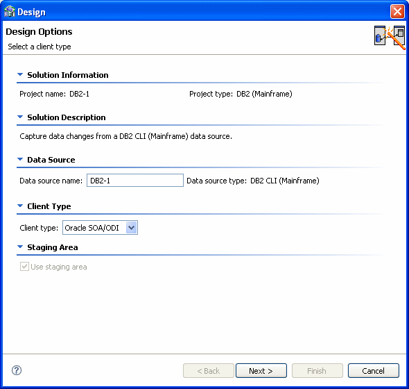
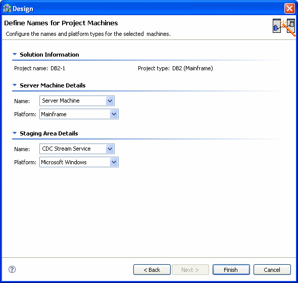
Click Design. The Design wizard opens. Use this wizard to enter the basic settings for your project.
Note:
The wizard screens are divided into sections. Some sections provide information only and other sections let you to enter information about the project. If you do not see any information or fields for entering information, click the triangle next to the section name to expand the section. -
In the Client Type you can select Oracle SOA/ODI only. The Use staging area is selected and cannot be changed, you must use a staging area with the OracleAS CDC Adapter for DB2.
-
Click Next.
The Design Wizard's second screen is displayed. In this step you configure the machines used in your solution. Enter the following information:
-
Server Machine Details: Information about the machine where Oracle Connect is installed. The selection here is always Server Machine and Mainframe.
-
Staging Area Details: Information about the machine platform where the staging area is located.
For the server machine Name, select one of the following:
-
CDC Stream Service: Select this if the Staging Area is on a staging area computer. This is the default selection.
-
Server Machine: Select this if the staging area is on the same computer where Oracle Connect is installed.
-
Client Machine: Select this if the Staging area is on the local compuer.
In the Platform list, select the operating system for the staging area. This can be Windows, Linux or UNIX. The available options are:
-
Microsoft Windows
-
HP-UX
-
IBM AIX
-
Sun Solaris
-
Linux (Red Hat)
-
Suse (Linux)
-
-
-
Click Finish. The wizard closes.
Set up the CDC Server
Click Implement in the Getting Started guide to open the Implementation guide.
In the Implementation guide, do the following to set up the CDC server:
You do the following to define the IP Address/host name and Port for the CDC server machine.
-
Click Machine.
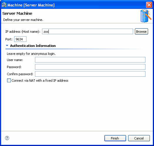
The machine definition screen is displayed:
-
In the IP address/host name field, do one of the following:
-
Enter the server machine's numeric IP address.
-
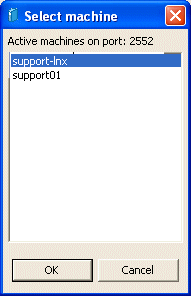
Click the Browse button and select the host machine from the ones presented, then click Finish.
Note:
The machine you enter must be compatible with the platform designated in the Design Wizard (Configure Solution Machines) screen.
-
-
Enter the port number.
The default port number is 2551.
-
If you want to connect with user authentication, enter a user name and password, with confirmation, in the Authentication Information area.
-
Select the Connect via NAT with a fixed IP address check box if you are using Network Access Translation and want to always used a fixed IP address for this machine.
-
Click OK.
Continue setting up the CDC Server on the z/OS computer.
To configure the DB2 data source as part of the DB2 CDC solution, perform the following procedure:
-
In the Solution perspective, click Implement.
-
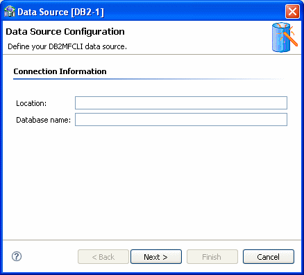
In the Server Configuration section, click Data Source. The following is displayed.
-
Enter the following information in the Data Source Configuration window:
-
Location: Enter the DB2 location name for the connected DB2 instance. The parameter should be specified if the connected DB2 instance is different than the instance defined in the MVSDEFAULTSSID parameter of the
ODBCINIfile. -
Database name: Enter the existing DB2 database name, only if you are creating new tables using AIS.
-
-
Click Next. Enter the following information in the next window:
-
Default Table Name: Enter the name of the default table owner for the DB2 database tables.
-
User Name and Password, if you must provide security credentials to the DB2 database.
-
-
Click Finish.
For information on DB2 data source properties, see the DB2 data source reference chapter.
In this step you define the starting point or event for the change capture and then indicate the name of the change logger. Do the following to set up the CDC service.
-
In the Solution perspective, click Implement.
-
In the Server Configuration section, click CDC Service. The CDC Service wizard is displayed.
-
In the first screen select one of the following to determine the Change Capture starting point:
-
On first access to the CDC (immediately when a staging area is used, otherwise, when a client first requests changes
-
Changes recorded in the journal after a specific date and time.
When you select this option, click Set time, and select the time and date from the dialog box that is displayed.
Note:
The DB2 agent does not support the All changes recorded in the journal mode. If you choose to consume changes from a specific date and time (time stamp), the DB2 agent uses the DSNJU004 module internally to find an archive or active log file that contains the corresponding log records. Then it reads the changes sequentially from the beginning of the file until the log record corresponding to the provided time stamp is found. -
-
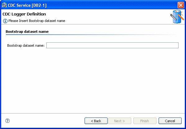
Click Next to define the logger. The following is displayed.
-
In the Bootstrap dataset name field, enter the name of the data set used to keep track of DB2 logs.
-
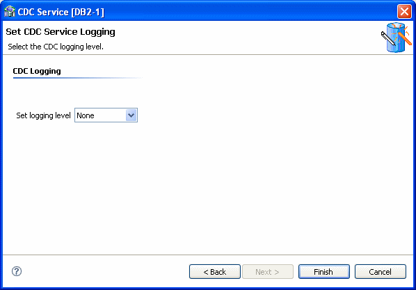
Click Next to go to the next step where you set the CDC Service Logging. Select the log level to use from the Logging level list.
Select one of the following from the list:
-
None
-
API
-
Debug
-
Info
-
Internal Calls
-
-
Click Finish.
Continue setting up the CDC Server on the z/OS computer.
Set up the Staging Area Server
Click Implement in the Getting Started guide to open the Implementation guide.
In the Implementation guide, do the following under the Stream Service Configuration section, to set up the staging area server:
Set Up the Staging Area Machine
To set up the machine for the staging area, do the following.
-
Under the Stream Service Configuration section, click Machine.
-
Use the same configurations used to Set up the Machine for the CDC server.
Continue setting up the staging area Server.
In this step you set up the stream service. The Stream Service configures the following:
-
Staging area
-
Filtering of changed columns
-
Auditing
Note:
Null filtering is currently unsupported. Filtering empty values is supported. Space values are truncated and are handled as empty values.-
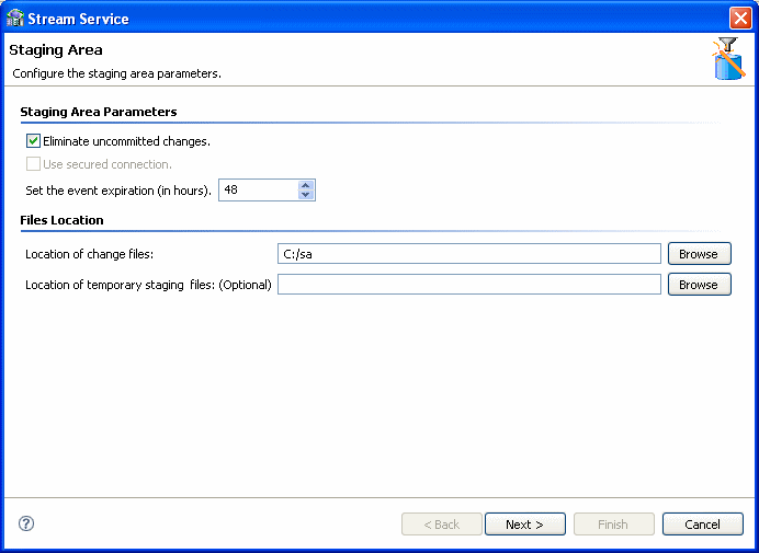
Click Stream Service. The Stream Service wizard opens.
Note:
This screen appears only if you selected the inclusion of a staging area in your solution. -
You can configure the following parameters in this screen:
-
Select Eliminate uncommitted changes to eliminate uncommitted changes from your CDC project.
-
Select the Use secured connection check box to configure the staging area to have a secured connection to the server. This is available only if you logged into the server using user name and password authentication.
-
Set the event expiration time in hours.
-
Under File Locations, click the Browse buttons to select the location of the changed files, and temporary staging files, if necessary.
-
-
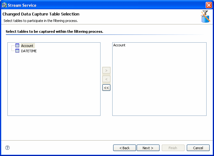
Click Next to select the tables to include in the filtering process.
-
Click the required tables in the left pane and move them to the right pane using the arrow keys.
Note: You can remove the tables and add new ones to be captured after you add the tables to the right pane. For more information, see Adding and Removing Tables.
-
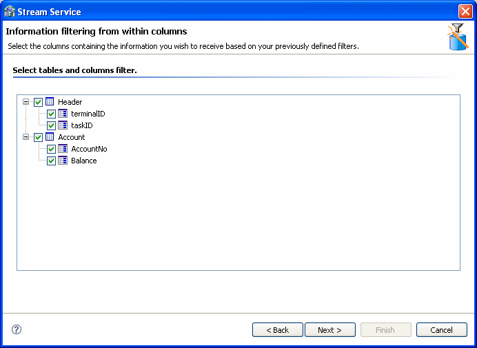
Click Next. From the tables selected above, select the columns that receive changes. Select the check box next to the table to use all columns in the table.
Note:
Table headers appear grouped in a separate table at the beginning of the list. You can also request the receipt of changes in the headers' columns.Any data changes in the columns selected are recorded.
-
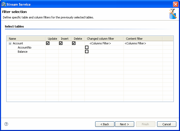
Click Next. The Filter selection screen is displayed. the types of changes you want to receive in the tables and which columns to display.
-
You can do the following in this screen:
Select the actions from which you want to receive change information:
-
-
Update
-
Insert
-
Delete
Note:
These items are all selected by default. -
-
Under the Changed Columns Filter column, select the columns for which you want to receive notification of changes.
Notes:
-
If you do not select a column, you receive notification of all changes.
-
If you select only one, you receive change information only if the field selected undergoes a change.
-
If you select several, but not all, then you receive change information only if any or all of the selected fields undergo a change
-
-
-
In the Content Filter column of the Filter screen, double-click a table column and then click the Browse button to filter content from the selected column.
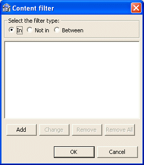
The Content Filter screen is displayed.
-
Select a filter type:
-
Select In for events to be returned where the relevant column value equals the values you specify (if a column is NULL, it is not captured).
-
Select Not In for events to be returned where the column value is not in the values you specify (if the column is NULL, it is captured).
-
Select Between for when the column value is between the two values you specify (if a column is NULL, it is not captured).
-
-
Click Add in the lower-left corner of the Content Filter screen.
Note:
If you select multiple conditions, you receive the change information if one condition is true. -
Depending on your selection, do one of the following:
-
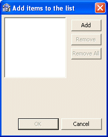
Click Add in the Add items to the list screen. Enter a value for events to be returned where the column value appears (or does not appear) in that value. To filter empty values ('') for the Not In filter type, leave this field blank in the dialog box that is displayed.
-
Repeat steps 12 as many times as necessary, and then proceed to step 16.
-
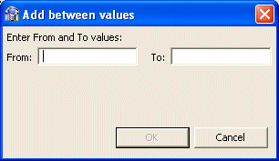
Click Add in the Add items to list screen.
The Add between values screen is displayed.
-
Enter values for events to be returned where the column value is between the two values you specify.
-
In the Content Filter screen, click Next.
-
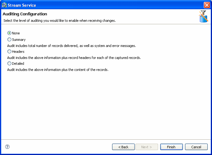
Select the required auditing level when receiving changes. Your options are:
-
None: For no changes.
-
Summary: For an audit that includes the total number of records delivered, system messages, and error messages.
-
Headers: For an audit that includes the total number of records delivered, system and error messages, and the record headers for each captured record.
-
Detailed: For an audit that includes the total number of records delivered, system and error messages, the record headers for each captured record, and the content of the records.
-
-
Click Finish.
Continue setting up the staging area Server.
Configure the Access Service Manager
In this step you set up a daemon workspace for the CDC adapter. Do the following to configure the access service manager.
-
Click Access Service Manager.
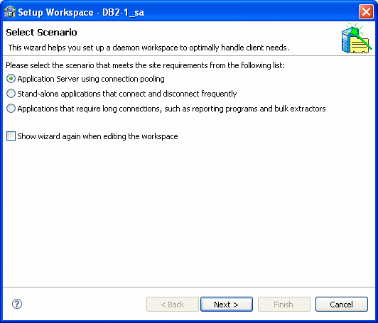
The Setup Workspace wizard opens.
-
Select the scenario that best meets your site requirements:
-
Application Server using connection pooling
-
Stand-alone applications that connect and disconnect frequently
-
Applications that require long connections, such as reporting programs and bulk extractors
-
-
Click Next.
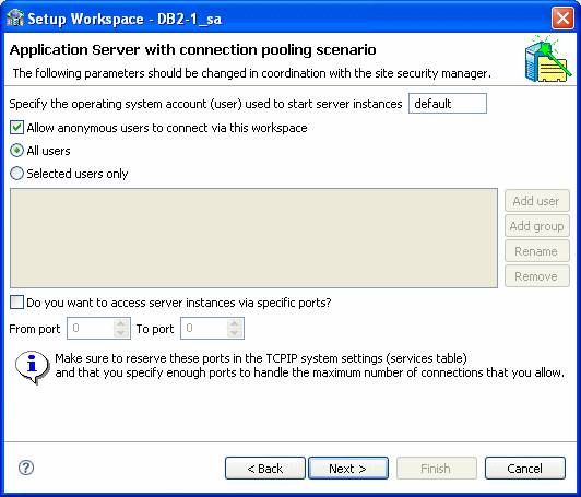
The Application Server with connection pooling scenario screen is used to create a workspace server pool. The parameters available depend on the selection you made in the first screen. The following are the available parameters:
-
If you selected Application Server using connection pooling:
-
What is the average number of expected concurrent connections? Enter the number of expected connections, which cannot be greater than the number of acutal available connections.
-
What is the maximum number of connections you want to open? Enter the number of connections you want opened.
-
-
If you selected Stand-alone applications that connect and disconnect frequently, in addition to the choices listed in the item above, you can also set the following:
-
What is the minimum number of server instances you want available at any time? Enter the number of instances, which cannot be greater than the number of actual available instances.
-
What is themaximum number of server instances you want available at any time? Enter the number of instances you want to be available.
-
-
If you selected Stand-alone applications that connect and disconnect frequently:
-
How many connections do you want to run concurrently? Enter the number of concurrent connections to run.
-
-
-
Click Next. In the next screen you set time out parameters. These parameters should be changed if the system is slow or overloaded. The parameters are:
-
How long do you want to wait for a new connection to be established? Enter the amount of time you want to wait for a new connection to be established (in seconds).
-
How long do you want to wait for a response that is usually quick? Change this parameter if you have a fast connection. Enter the amount of time to wait for a response (in seconds).
-
-
Click Next. In the next screen you set security parameters. You should consult with the site security manager before changing these parameters.
Edit the following parameters in this screen:
-
Enter the operating system account (user name) used to start server instances.
-
Select Allow anonymous users to connect via this workspace, to allow this option.
-
Enter the permissions for the workspace. You can allow All users to access the workspace, or select Selected users only to allow only selected users/groups to have exclusive access.
-
Select Do you want to access server instances via specific ports, to allow this option. If this option is cleared, the defaults are used.
If you select this option, indicate the From port and To port and ensure that you reserve these ports in the TCP/IP system settings.
-
-
Click Next.
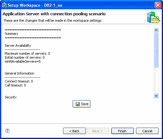
The summary screen opens.
-
Click Save and then click Finish.
When you complete all the Implementation operations, a check mark (✓) is displayed next to every link. Click Done to return so you can begin Deploying a Change Data Capture.
Continue setting up the staging area Server.
Deploying a Change Data Capture
After you complete the design and implementation guides, the following procedures are available.
-
Deployment Procedure: This section is used to deploy the project.
-
Control: This section is used to activate or deactivate workspaces after the project is deployed and you are ready to consume changes. In this section, you can deactivate the workspace anytime you want to suspend consumption of changes from the staging area.
Do the following to deploy the CDC solution:
-
Click Deploy. The Deployment Procedure and Control sections are displayed in the Deployment view.
-
Click Deploy in the Deployment Procedure section.
Oracle Studio processes the naming information. This may take a few minutes. If there are naming collisions, a message is displayed asking if you want Oracle Studio to resolve them.
-
Click Yes to resolve any naming collisions.
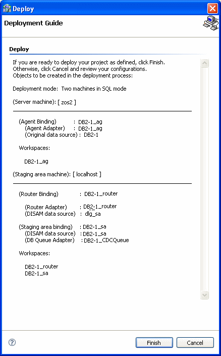
The Deployment Guide screen is displayed.
-
If you are ready to deploy, click Finish.
Otherwise, click Cancel and you can return to Create a CDC Project, Set up the CDC Server, or Set up the Staging Area Server to make any changes.
If this project was deployed previously, you are notified that re-deployment overrides the previous instance.
Notes:
-
When you redeploy a project where the metadata is changed, the Staging Area (SA) tables should be deleted so that no incorrect information is reported.
-
When you redeploy a solution, a new binding is created for the solution. The new binding is created with the default parameters only. Any temporary features that were added are lost.
-
-
Where applicable, click OK to redeploy.
-
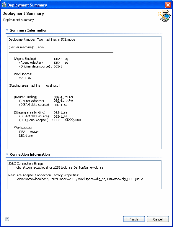
Click the Deployment Summary link.
The Deployment Summary is displayed. It includes the ODBC connection string and JDBC connection string, as well as specific logger scripts to enable CDC capturing.
-
Cut and paste any information required from the Deployment Summary screen to your environment as necessary.
-
If there is nothing wrong with your deployment results, click Finish.
If you found problems, click Cancel and to return Create a CDC Project, Set up the CDC Server, or Set up the Staging Area Server to modify the solution.
Note:
If you are redeploying a solution you must follow these directions to ensure that thecontext and agent_context fields of the SERVICE_CONTEXT table must be saved. Follow these directions to save the fields:
-
In the staging area data source run: select context,
agent_context from SERVICE_CONTEXT; and save the returned values. -
Delete the
SERVICE_CONTEXTtable physical files. -
Redeploy the solution.
-
Activate the router to create the
SERVICE_CONTEXTtable. -
Disable the router.
-
In the staging area data source run:
insert into SERVICE_CONTEXT (context, agent_context) values('XXX', 'YYY'). This inserts the saved values to the SERVICE_CONTEXT table. -
Activate the solution.
Activating and Deactivating Solution Workspaces
In the Project guide for your OracleAS CDC adapter solution, click Deploy, then do one of the following to activate or deactivate the workspaces for a solution
-
To activate workspaces, under the Control section iclick the Activate Workspaces link.
-
To deactivate workspaces, click the Deactivate Workspaces link.
During the activation/deactivation process, you may receive messages indicating that the daemon settings on one or more of the machines involved in your solution have changed. Click Yes to proceed.
