6 Working with Integration Interfaces
This chapter describes how to work with integration interfaces in Oracle Data Integrator. The demonstration environment includes several example interfaces. In this chapter you learn how to create the following interfaces:
-
Pop.TRG_CUSTOMER integration interface: This interface loads the data from the SRC_CUSTOMER table in the Orders Application - HSQL model into the TRG_CUSTOMER target table in the Sales Administration - HSQL model.
-
Pop.TRG_SALES integration interface: This interface loads the data from the SRC_ORDERS table and from the SRC_ORDER_LINES table in the Orders Application - HSQL model into the TRG_SALES target table in the Sales Administration - HSQL model.
This chapter includes the following sections:
6.1 Pop. TRG_CUSTOMER Interface Example
This section contains the following topics:
6.1.1 Purpose and Integration Requirements
This section describes the integration features and requirements the integration interface Pop. TRG_CUSTOMER is expected to meet.
The purpose of the Pop. TRG_CUSTOMER interface is to load the data from the SRC_CUSTOMER table in the Orders Application - HSQL model into the TRG_CUSTOMER target table in the Sales Administration - HSQL model.
However, the SRC_CUSTOMER table does not contain all of the data that is required for this operation. The following information has to be added to the target table:
-
The age range (AGE_RANGE) that is defined in the SRC_AGE_GROUP flat file in the Parameters - FILE model corresponds to the AGE attribute in the source table.
-
The last and first names of the customer sales rep. (LAST_NAME and FIRST_NAME) that is defined in the SRC_SALES_PERSON file in the Parameters - FILE model correspond to the sales rep. number (SALES_PERS_ID) in the source table.
-
The transformed value of the numeric data (0, 1, 2) from the DEAR column in the source table into an standard salutation text string in the target (Mr, Mrs, or Ms).
-
The concatenated first and last names of the source customers.
The source data is not always consistent with the integrity rules implemented in the target environment. For this interface, the data has to be cleansed by verifying that all constraints are satisfied and by storing invalid rows in an error table rather than in our target database. In this example, two important integrity rules must be satisfied:
-
Customers must be older than 21 (condition AGE > 21)
-
The customers must be associated with a city (CITY_ID) that exists in the TRG_CITY table (reference FK_CUST_CITY)
The functional details for these rules and the procedure to follow are given in Section 6.1.3, "Creating the Integration Interface".
6.1.2 Interface Definition
This section describes the integration interface Pop. TRG_CUSTOMER that will be created in this example. See Section 6.1.3, "Creating the Integration Interface" for more information.
The Pop. TRG_CUSTOMER interface uses the following data and transformations:
-
One target datastore. Table 6-1 lists the details of the target datastore.
-
Three source datastores. Table 6-2 lists the details of the source datastores.
Table 6-2 Source Datastore Details of Pop. TRG_CUSTOMER
Model Datastore Description Type Orders Application - HSQL
SRC_CUSTOMER
Customers in the source system
HSQL table
Parameters - FILE
SRC_AGE_GROUP
Age bracket file
File delimited by semicolons
Parameters - FILE
SRC_SALES_PERSON
Salesperson file
File of fixed-size records
-
One join. Table 6-3 lists the details of the join.
-
One lookup table. Table 6-4 lists the details of the lookup table.
-
Several transformation rules. Table 6-5 lists the details of the transformation rules.
Table 6-5 Transformation Rules used in Pop. TRG_CUSTOMER
Target Column Origin SQL Rule Execution Location CUST_ID
SRC_CUSTOMER.CUSTID
SRC_CUSTOMER.CUSTIDSource
DEAR
If SRC_CUSTOMER.DEAR = 0 then 'MR'
If SRC_CUSTOMER.DEAR = 1 then 'MRS' else 'MS'
CASEWHEN(SRC_CUSTOMER.DEAR=0, 'MR', CASEWHEN( SRC_CUSTOMER.DEAR=1, 'MRS', 'MS') )Source
CUST_NAME
Concatenation of SRC_CUSTOMER.FIRST_NAME and SRC_CUSTOMER.LAST_NAME in upper case
SRC_CUSTOMER.FIRST_NAME || ' ' || UCASE(SRC_CUSTOMER.LAST_NAME)Source
ADDRESS
SRC_CUSTOMER.ADDRESS
SRC_CUSTOMER.ADDRESSSource
CITY_ID
SRC_CUSTOMER.CITY_ID
SRC_CUSTOMER.CITY_IDSource
PHONE
SRC_CUSTOMER.PHONE
SRC_CUSTOMER.PHONESource
AGE
SRC_CUSTOMER.AGE
SRC_CUSTOMER.AGESource
AGE_RANGE
SRC_AGE_GROUP.AGE_RANGE
SRC_AGE_GROUP.AGE_RANGEStaging area
SALES_PERS
Concatenation of SRC_SALES_PERSON.FIRST_NAME and SRC_SALES_PERSON.LAST_NAME in uppercase
SRC_SALES_PERSON.FIRST_NAME || ' ' || UCASE(SRC_SALES_PERSON.LAST_NAME)Staging area
CRE_DATE
Today's date
CURDATE()Target
UPD_DATE
Today's date
CURDATE()Target
6.1.3 Creating the Integration Interface
This section describes how to create the Pop. TRG_CUSTOMER integration interface. To create the Pop. TRG_CUSTOMER interface perform the following procedure:
6.1.3.1 Insert a New Integration Interface
To create a new integration interface:
-
In Designer Navigator, expand the Demo project node in the Projects accordion.
-
Expand the Sales Administration node.
-
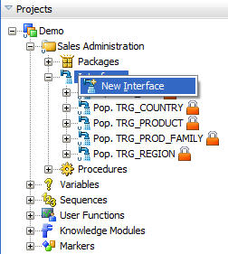
In the Sales Administration folder, right-click the Interfaces node and select New Interface as shown in Figure 6-1.
The Interface Editor is displayed.
-
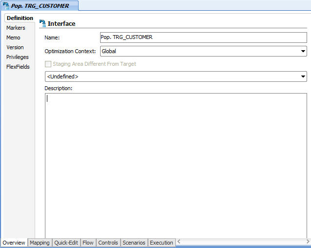
On the Definition tab of the Interface Editor, enter the name of your interface (Pop. TRG_CUSTOMER) in the Name field as shown in Figure 6-2.
6.1.3.2 Define the Target Datastore
The target datastore is the element that will be loaded by the interface.
To insert the target datastore in the Pop. TRG_CUSTOMER interface:
-
Go to the Mapping tab of the Interface Editor.
-
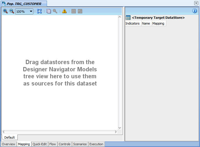
The Mapping tab displays in the interface diagram as shown in Figure 6-3.
-
In the Designer Navigator, expand the Models accordion and the Sales Administration - HSQL model.
-
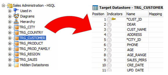
Select the TRG_CUSTOMER datastore under the Sales Administration - HSQL model and drag it into the Target Datastore panel as shown in Figure 6-4.
6.1.3.3 Define the Source Datastores
The source datastores contain data used to load the target datastore. Two types of datastores can be used as an interface source: datastores from the models and temporary datastores that are the target of an interface. This example uses datastores from the Orders Application - HSQL and Parameters - FILE models.
To add source datastores to the Pop. TRG_CUSTOMER interface:
-
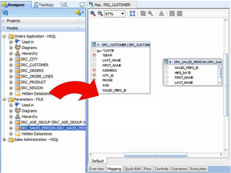
In the Mapping tab, drag the following source datastores into the Source Diagram:
-
SRC_CUSTOMER from the Orders Application - HSQL model
-
SRC_SALES_PERSON from the Parameters - FILE model
-
-
The Mapping tab of your Interface Editor should look like shown in Figure 6-5.
-
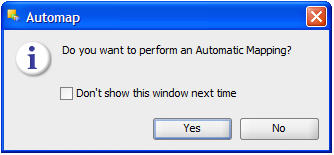
The Automap Dialog appears as shown in Figure 6-6.
Click Yes to confirm the use of automatic field to field mapping by Oracle Data Integrator. The automatic mapping is performed when you drop a source datastore in the Source Diagram.
6.1.3.4 Define the Lookup Table
This section describes how to create a lookup that defines that the customer's age must be between the minimum and maximum ages in the file.
A lookup is a datastore (from a model or the target datastore of an interface) - called the lookup table - associated to a source datastore - the driving table - via a join expression and from which data can be fetched and used in mappings.
Lookup tables are added with the Lookup Wizard.
To create a lookup in the Pop. TRG_CUSTOMER interface:
-
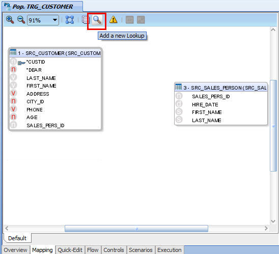
From the Source Diagram toolbar menu, select Add a new Lookup as shown in Figure 6-7.
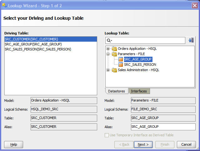
The Lookup Wizard opens.
-
In the Lookup Wizard, select SRC_CUSTOMER(SRC_CUSTOMER) from the Driving Table list.
Note that source datastores for the current diagram appear here and that lookups do not appear in the list.
-
From the Lookup Table pane select the SRC_AGE_GROUP datastore from the Parameters - FILE model on the Datastores tab.
The SRC_AGE_GROUP datastore will be used as a lookup table.
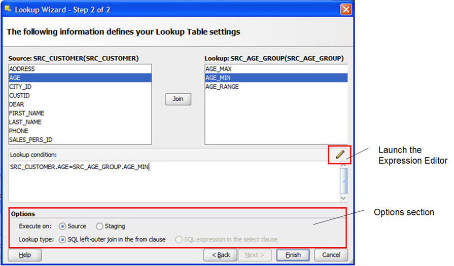
Figure 6-8 shows the first screen of the Lookup Wizard.
-
Click Next.
-
On the left pane, select the AGE source column from the driving table.
-
On the right pane, select the AGE_MIN column of the lookup table.
-
Click Join. The join condition appears in the Lookup condition text field as shown in Figure 6-9.
-
In the Options section, select Staging for the execution location.
-
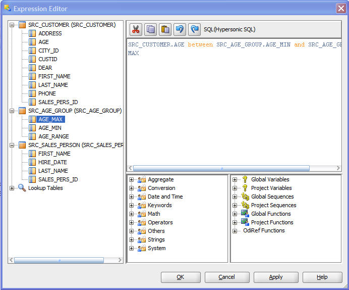
Click Launch the Expression Editor and modify the lookup condition as follows:
-
Replace the equals sign (
=) with the stringbetween -
Add the following string at the end of the expression:
and SRC_AGE_GROUP.AGE_MAXThis adds the AGE_MAX column from the SRC_AGE_GROUP datastore.
-
-
You should have the following join expression:
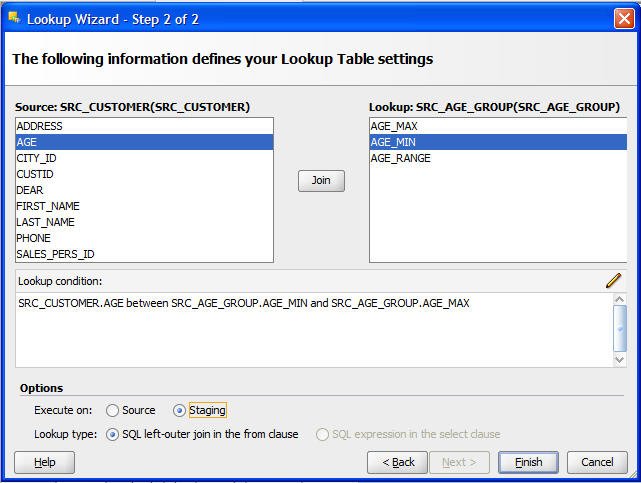
SRC_CUSTOMER.AGE between SRC_AGE_GROUP.AGE_MIN and SRC_AGE_GROUP.AGE_MAXThis corresponds to a join between the SRC_CUSTOMER and the SRC_AGE_GROUP datastore and defines that the customer's age must between the minimum and maximum ages in the file. Figure 6-10 shows the Expression Editor with the lookup condition.
-
In the Expression Editor, click OK.
-
The modified lookup condition appears in the Lookup Wizard as shown in Figure 6-11.
-
Click Finish.
The Source Diagram appears as shown in Figure 6-12.
Note:
If references were already defined in the models to link the source datastores, these references would have appeared automatically as joins in the source diagram.6.1.3.5 Define the Join between the Source Datastores
This section describes how to define a join between the source datastores.
To create the join defined in Table 6-3:
-
In the Source Diagram, select the SALES_PERS_ID column of the SRC_CUSTOMER datastore.
-
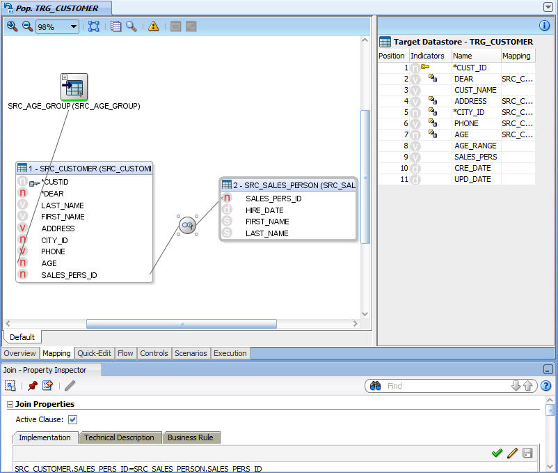
Drag and drop it on the SALES_PERS_ID column of the SRC_SALES_PERSON datastore. A join linking the two datastores appears as shown in Figure 6-13. This is the join on the sales representative identifier.
6.1.3.6 Define the Mappings
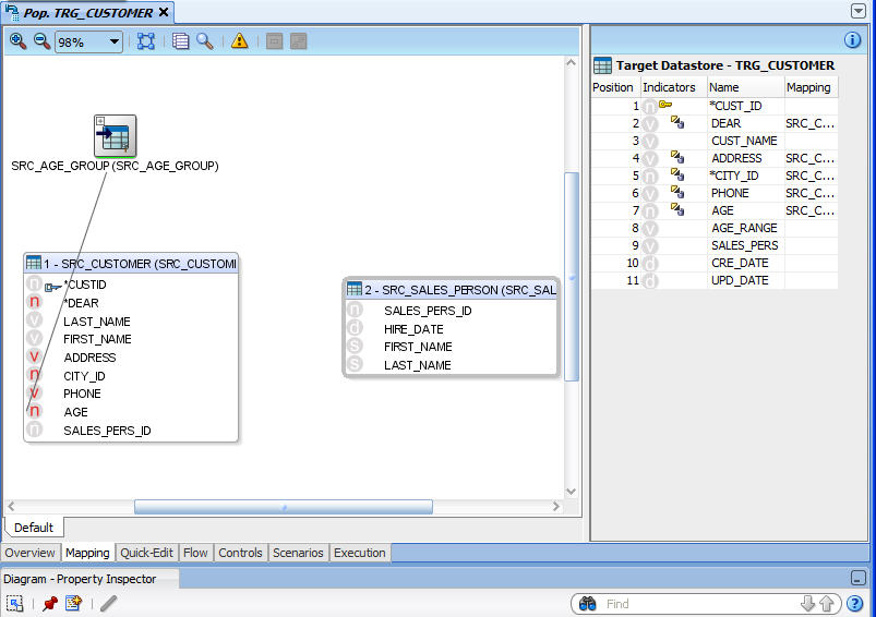
In the Target Datastore panel of your interface, columns with names that match their sources are automatically mapped. The automatic mapping is done by the matching of the column names. Most of the transformation rules listed in Table 6-5 have been defined by the automatic mapping. In addition to this automatic mappings, you have to define the transformation rules for the following fields: CUST_ID, DEAR, CUST_NAME, AGE_RANGE, SALES_PERS, CRE_DATE and UPD_DATE.
The transformation rules, also called mappings, are defined on the target column.
The CUST_ID mapping maps the SRC_CUSTOMER.CUSTID source column to the TRG_CUSTOMER.CUST_ID target column. Note that these 2 columns have not been automatically mapped, since their names are slightly different.
To define the mapping for the CUST_ID target column:
-
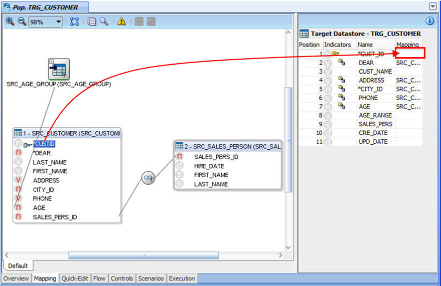
In the Source Diagram, select the CUSTID column in the SRC_CUSTOMER datastore.
-
Drag it into the Mapping field in the Target Datastore panel as shown in Figure 6-14.
-
Select the Mapping field in the Target Datastore to display its properties in the Property Inspector.
-
Verify that the execution location is set to Source as shown in Figure 6-15.
Note:
Possible execution locations are: Source, Target, and Staging Area. Make sure that you select the environment in which your transformation will be executed as specified in Table 6-5. Select this environment by clicking on one of the radio buttons as shown in Figure 6-15.
This transformation rule maps the source datastore's DEAR column (numeric) as a string expression (0 -->'MR', 1 -->'MRS', 2 -->'MS').
To define the mapping for the DEAR target column:
-
In the Target Datastore panel, select the Mapping field of the DEAR target column to display the mapping properties in the Property Inspector.
Tip:
Click Freeze View in the Property Inspector toolbar to continue displaying the current contents of the Property Inspector even if you select a different component that would normally change the contents of the Property Inspector. The Freeze View button is:
To unfreeze a frozen instance of the Property Inspector and allow it to track the active selection, click Freeze View again.
-
In the Implementation field, enter the following mapping expression:
CASEWHEN(SRC_CUSTOMER.DEAR=0, 'MR', CASEWHEN( SRC_CUSTOMER.DEAR=1, 'MRS', 'MS') )Tip:
You can drag source columns, for example the SRC_CUSTOMER.DEAR column, into the Implementation field. -
Verify that the execution location is set to Source.
This transformation rule maps the concatenated value of the first name and uppercase last name of each customer.
To define the mapping for the CUST_NAME target column:
-
In the Target Datastore panel, select the Mapping field of the CUST_NAME target column to display the mapping properties in the Property Inspector.
-
In the Implementation field, enter the following mapping expression:
SRC_CUSTOMER.FIRST_NAME || ' ' || UCASE(SRC_CUSTOMER.LAST_NAME)Tip:
Use the Expression Editor to create this rule. By using the Expression Editor, you can avoid most common syntax errors. -
Verify that the execution location is set to Source.
This mapping maps the SRC_AGE_GROUP.AGE_RANGE to the TRG_CUSTOMER.AGE_RANGE.
To define the mapping for the AGE_RANGE target column:
-
In the Target Datastore panel, select the Mapping field of the AGE_RANGE target column to display the mapping properties in the Property Inspector.
-
In the Implementation field, enter the following mapping expression:
SRC_AGE_GROUP.AGE_RANGE -
Verify that the execution location is set to Staging Area.
Note:
This rule must be executed in the staging area! The source in this example is a flat file, and as such is not associated to an engine that supports concatenation.
This will map the concatenated value of the first name and uppercase last name of each salesperson.
To define the mapping for the SALES_PERS target column:
-
In the Target Datastore panel, select the Mapping field of the SALES_PERS target column to display the mapping properties in the Property Inspector.
-
In the Implementation field, enter the following mapping expression:
SRC_SALES_PERSON.FIRST_NAME || ' ' || UCASE(SRC_SALES_PERSON.LAST_NAME) -
Verify that the execution location is set to Staging Area.
Note:
This rule must be executed in the staging area! The source in this example is a flat file, and as such is not associated to an engine that supports concatenation.
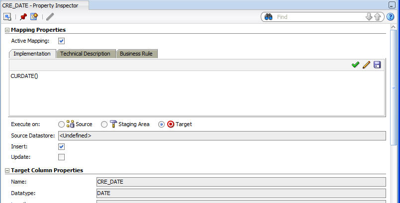
To define the mapping for the CRE_DATE target column:
-
In the Target Datastore panel, select the Mapping field of the CRE_DATE target column to display the mapping properties in the Property Inspector.
-
In the Implementation field, enter the following mapping expression:
CURDATE()
-
Verify that Active Mapping is selected.
-
Verify that the execution location is set to Target.
-
Unselect Update. The mapping will be performed only on Insert.
-
The Property Inspector of the CRE_DATE mapping appears as shown in Figure 6-16.
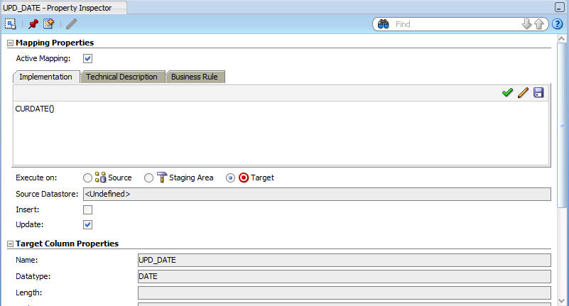
To define the mapping for the UPD_DATE target column:
-
In the Target Datastore panel, select the Mapping field of the UPD_DATE target column to display the mapping properties in the Property Inspector.
-
In the Implementation field, enter the following mapping expression:
CURDATE()
-
Verify that Active Mapping is selected.
-
Verify that the execution location is set to Target.
-
Unselect Insert. The mapping will be performed only on Update.
-
The Property Inspector of the UPD_DATE mapping appears as shown in Figure 6-17.
Notes on the Expression Editor
-
The Expression Editor that is used to build the Expressions does not contain all of the functions specific to a technology. It contains only functions that are common to a large number of technologies. The fact that a function does not appear in the Expression Editor does not prevent it from being entered manually and used in an Expression.
-
If you were to execute this mapping on the target, the Expression Editor would give you the syntax for your target system (also Hypersonic SQL in this case).
-
Clicking Check the expression in the DBMS calls your source server to check the syntax of the SQL code you have entered. This check can only be performed when your rule is entirely executed on the source server.
Your transformation rules appear in the Target Datastore panel as shown in Figure 6-18.
Two types of icons are used in the Indicators column of the Target Datastore panel:
-
The first letter of the data type in the target column (n: numeric, v: varchar, d: date)
-
The execution location of the expression.
Note that you can also use the Quick-Edit Editor to create and view an integration interface. See "Using the Quick-Edit Editor" in the Oracle Fusion Middleware Developer's Guide for Oracle Data Integrator for more information.
6.1.3.7 Define the Data Loading Strategies (LKM)
The data loading strategies are defined in the Flow tab of the Interface Editor. Oracle Data Integrator automatically computes the flow depending on the configuration in the interface's diagram. It proposes default KMs for the data flow. The Flow tab enables you to view the data flow and select the KMs used to load and integrate data.
Loading Knowledge Modules (LKM) are used for loading strategies and Integration Knowledge Modules (IKM) are used for integration strategies.
You have to define the way to retrieve the data from the SRC_AGE_GROUP, SRC_SALES_PERSON files and from the SRC_CUSTOMER table in your source environment.
To define the loading strategies:
-
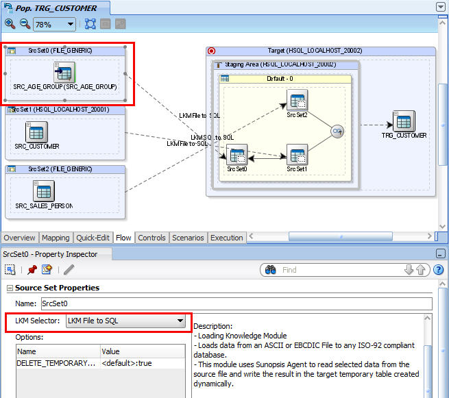
In the Flow tab of the Interface Editor, select the source set that corresponds to the loading of the SRC_AGE_GROUP file. In this example, this is the SrcSet0 (FILE_GENERIC). The Property Inspector should display the properties of this source set.
-
In the Property Inspector, verify that the LKM File to SQL is selected in the LKM Selector list as shown in Figure 6-19.
-
Select the source set that corresponds to the loading of the SRC_CUSTOMER table.
-
In the Property Inspector, verify that the LKM SQL to SQL is selected in the LKM Selector list.
6.1.3.8 Define the Data Integration Strategies (IKM)
After defining the loading phase, you need to define the strategy to adopt for the integration of the data into the target table.
To define the integration strategies:
-
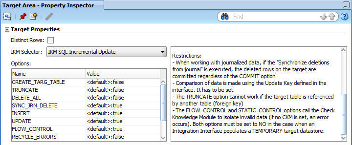
In the Flow tab of the Interface Editor, select the Target object in the Flow Diagram. The Property Inspector should display the properties of the target.
-
In the Property Inspector, verify that the IKM SQL Incremental Update is selected in the IKM Selector list.
-
In the knowledge module options, leave the default values. The Property Inspector appears as shown in Figure 6-20.
The KM options enable to control certain aspects of the integration strategy. For example, the FLOW_CONTROL option triggers the flow control operations of the data before inserting it into the target table.
Note:
Only Knowledge Modules imported to your Project appear in the KM Selector lists. The demonstration environment already includes the Knowledge Modules required for the getting started examples. You do not need to import KMs into the demonstration Project.For more information on importing KMs into your Projects, see "Importing a KM" in the Oracle Fusion Middleware Developer's Guide for Oracle Data Integrator.
6.1.3.9 Define the Data Control Strategy
In Section 6.1.3.7, "Define the Data Loading Strategies (LKM)" and Section 6.1.3.8, "Define the Data Integration Strategies (IKM)" you have specified the data flow from the source to the target. You must now define how to check your data (CKM) and the constraints and rules that must be satisfied before integrating the data.
To define the data control strategy:
-
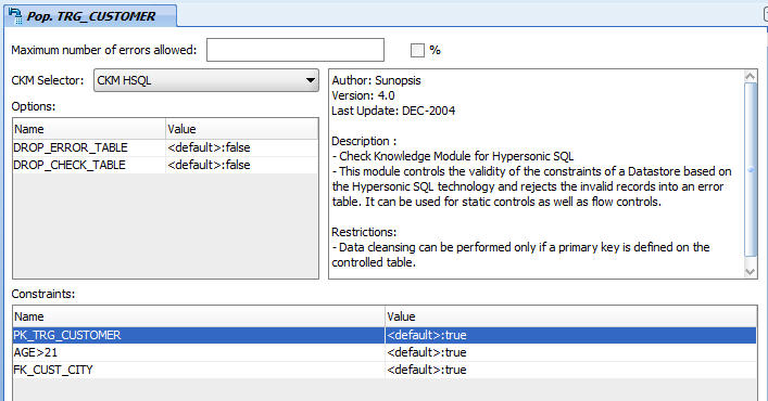
In the Controls tab of the Interface Editor, verify that the CKM HSQL is selected.
-
In the Constraints section, set the constraints that you wish to verify to
true.-
PK_TRG_CUSTOMER
-
AGE >21
-
FK_CUST_CITY
The Controls tab appears as shown in Figure 6-21.
-
-
From File main menu, select Save.
The Pop. TRG_CUSTOMER interface is now ready to be executed.
6.2 Pop. TRG_SALES Interface Example
This section contains the following topics:
6.2.1 Purpose and Integration Requirements
This section describes the integration features and requirements the integration interface Pop. TRG_SALES is expected to meet.
The purpose of this interface is to load the SRC_ORDERS table of orders and the SRC_ORDER_LINES table of order lines from the Orders Application - HSQL model into the TRG_SALES target table in the Sales Administration - HSQL model. The data must be aggregated before it is integrated into the target table. Only orders whose status is CLO are to be used.
However, the source data is not always consistent with the integrity rules present in the target environment. For this transformation, we want to cleanse the data by verifying that all of the constraints are satisfied. We want to place any invalid rows into an error table rather that into our target database. In our case, two important integrity rules must be satisfied:
-
The sales must be associated with a customer (CUST_ID) that exists in the TRG_CUSTOMER table (reference FK_SALES_CUST)
-
The sales must be associated with a product (PRODUCT_ID) that exists in the TRG_PRODUCT table (reference FK_SALES_PROD)
The functional details for these rules and the procedure to follow are given in Section 6.2.3, "Creating the Integration Interface".
6.2.2 Interface Definition
This section describes the integration interface Pop. TRG_SALES that will be created in this example. See Section 6.2.3, "Creating the Integration Interface" for more information.
The Pop.TRG_SALES interface uses the following data and transformations:
-
One target datastore. Table 6-7 lists the details of the target datastore.
-
Two source datastores. Table 6-8 lists the details of the source datastores.
-
One join. Table 6-9 lists the details of the join.
-
One Filter. Table 6-10 lists the details of the filter.
-
Several transformation rules. Table 6-11 lists the details of the transformation rules.
Table 6-11 Transformation Rules used in Pop. TRG_CUSTOMER
Target Column Origin SQL Rule Execution Location CUST_ID
CUST_ID from SRC_ORDERS
SRC_ORDERS.CUST_ID
Source
PRODUCT_ID
PRODUCT_ID from SRC_ORDER_LINES
SRC_ORDER_LINES.PRODUCT_ID
Source
FIRST_ORD_ID
Smallest value of ORDER_ID
MIN(SRC_ORDERS.ORDER_ID)
Source
FIRST_ORD_DATE
Smallest value of the ORDER_DATE from SRC_ORDERS
MIN(SRC_ORDERS.ORDER_DATE)
Source
LAST_ORD_ID
Largest value of ORDER_ID
MAX(SRC_ORDERS.ORDER_ID)
Source
LAST_ORD_DATE
Largest value of the ORDER_DATE from SRC_ORDERS
MAX(SRC_ORDERS.ORDER_DATE)
Source
QTY
Sum of the QTY quantities from the order lines
SUM(SRC_ORDER_LINES.QTY)
Source
AMOUNT
Sum of the amounts from the order lines
SUM(SRC_ORDER_LINES.AMOUNT)
Source
PROD_AVG_PRICE
Average amount from the order lines
AVG(SRC_ORDER_LINES.AMOUNT)
Source
6.2.3 Creating the Integration Interface
This section describes how to create the Pop. TRG_SALES integration interface. To create the Pop. TRG_SALES interface perform the following procedure:
Note that you can also use the Quick-Edit Editor to create an integration interface. See "Using the Quick-Edit Editor" in the Oracle Fusion Middleware Developer's Guide for Oracle Data Integrator for more information.
6.2.3.1 Insert a New Integration Interface
To create a new integration interface:
-
In Designer Navigator, expand the Demo project node in the Projects accordion.
-
Expand the Sales Administration node.
-
In the Sales Administration folder, right-click the Interfaces node and select New Interface.
The Interface Editor is displayed.
-
On the Definition tab of the Interface Editor, enter the name of your interface (Pop. TRG_SALES) in the Name field.
6.2.3.2 Define the Target Datastore
To insert the target datastore in the Pop. TRG_SALES interface:
-
Go to the Mapping tab of the Interface Editor.
-
In the Designer Navigator, expand the Models accordion and the Sales Administration - HSQL model.
-
Select the TRG_SALES datastore under the Sales Administration - HSQL model and drag it into the Target Datastore panel.
6.2.3.3 Define the Source Datastores
The Pop. TRG_SALES interface example uses datastores from the Orders Application - HSQL model.
To add source datastores to the Pop. TRG_SALES interface:
-
In the Mapping tab, drag the following source datastores into the Source Diagram:
-
SRC_ORDERS from the Orders Application - HSQL model
-
SRC_ORDER_LINES from the Orders Application - HSQL model
-
-
In the Automap Dialog click Yes.
6.2.3.4 Define Joins between the Source Datastores
This section describes how to define joins between the source datastores.
To create the join defined in Table 6-9:
-
In the Source Diagram, select the ORDER_ID column of the SRC_ORDERS datastore.
-
Drag and drop it on the ORDER_ID column of the SRC_ORDER_LINES datastore.
A join linking the two datastores appears. This is the join on the order number.
The join has the following expression:
SRC_ORDERS.ORDER_ID=SRC_ORDER_LINES.ORDER_ID
6.2.3.5 Define the Order Filter
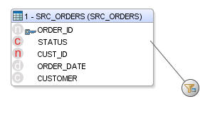
In this example, only completed orders should be retrieved. A filter needs to be defined on the SRC_ORDERS datastore.
To define the filter:
-
In the Source Diagram, select the STATUS column of the SRC_ORDERS datastore and drag it onto the Source Diagram.
-
The filter appears as shown in Figure 6-22.
-
Select the filter in the Source Diagram to display the filter properties in the Property Inspector.
-
In the Implementation tab of the Property Inspector, modify the filter rule by typing:
SRC_ORDERS.STATUS = 'CLO'
6.2.3.6 Define the Transformation Rules
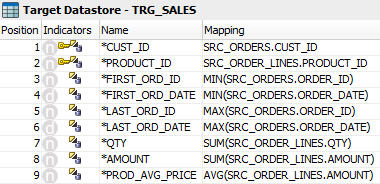
In the Target Datastore panel of your interface, columns with names that match their sources are automatically mapped. The automatic mapping is done by the matching of the column names. Most of the transformation rules listed in Table 6-11 have been defined by the automatic mapping. In addition to this automatic mappings, you have to define the transformation rules for the following fields: FIRST_ORD_ID, FIRST_ORD_DATE, LAST_ORD_ID, LAST_ORD_DATE, QTY, AMOUNT, and PROD_AVG_PRICE.
To manually define a mapping of the target column:
-
In the Target Datastore Panel, select the target column to display the mapping properties in the Property Inspector.
-
In the Property Inspector, click Freeze View so that the mapping of the target column is displayed.
-
Create the transformation rule either by:
-
Dragging the source column into the Mapping field in the Target Datastore panel
-
Dragging the required columns from the source datastores into the Implementation field in the Property Inspector
-
Editing the mapping expression in the Expression Editor
-
-
Select the execution location: Source, Target or Staging Area. Make sure that you select the environment in which your transformation will be executed as specified in Table 6-11.
-
Validate the syntax by clicking Check the expression in the DBMS.
-
Save the expression by clicking Save your expression.
Implement the following rules in the mappings:
-
FIRST_ORD_ID: Drag the SRC_ORDERS.ORDER_ID column into the Implementation field. Enter the following text in the Implementation field:
MIN(SRC_ORDERS.ORDER_ID)This transformation rule maps the minimum value of the ORDER_ID column in your SRC_ORDERS table to the FIRST_ORD_ID column in your target table.
-
FIRST_ORD_DATE: Drag the SRC_ORDERS.ORDER_DATE column into the Implementation field. Enter the following text in the Implementation field:
MIN(SRC_ORDERS.ORDER_DATE)This transformation rule maps the minimum value of the ORDER_DATE column in your SRC_ORDERS table to the FIRST_ORD_DATE column in your target table.
-
LAST_ORD_ID: Drag-and-drop the SRC_ORDERS.ORDER_ID column into the Implementation field. Enter the following text in the Implementation field:
MAX(SRC_ORDERS.ORDER_ID)This transformation rule maps the maximum value of the ORDER_ID column in your SRC_ORDERS table to the LAST_ORD_ID column in your target table.
-
LAST_ORD_DATE: Drag the SRC_ORDERS.ORDER_DATE column into the Implementation field. Enter the following text in the Implementation field:
MAX(SRC_ORDERS.ORDER_DATE)This transformation rule maps the maximum value of the ORDER_DATE column in your SRC_ORDERS table to the LAST_ORD_DATE column in your target table.
-
QTY: Enter the following text in the Implementation field:
SUM(SRC_ORDER_LINES.QTY)This transformation rule maps the sum of the product quantities to the QTY column in your target table.
-
AMOUNT: Enter the following text in the Implementation field:
SUM(SRC_ORDER_LINES.AMOUNT)This transformation rule maps the sum of the product prices to the AMOUNT column in your target table.
-
PROD_AVG_PRICE: Drag the SRC_ORDERLINES.AMOUNT column into the Implementation field. Enter the following text in the Implementation field:
AVG(SRC_ORDER_LINES.AMOUNT)This transformation rule maps the average of the product prices to the PROD_AVG_PRICE column in your target table.
Review carefully your mapping rules and make sure that you have defined the rules as shown in Figure 6-23.
Note that even though this example uses aggregation functions, you do not have to specify the group by rules: Oracle Data Integrator will infer that from the mappings, applying SQL standard coding practices.
6.2.3.7 Define the Data Loading Strategies (LKM)
In the Flow tab, Oracle Data Integrator indicates the various steps that are performed when the interface is executed.
In the Flow tab you define how to load the result of the orders and order line aggregates into your target environment with a Loading Knowledge Module (LKM).
To define the loading strategies:
-
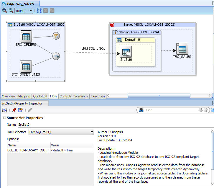
In the Flow tab of the Interface Editor, select the source set that corresponds to the loading of the order line's filtered aggregate results. In this example, this is the SrcSet0 (HSQL_LOCALHOST_2000).
-
In the Property Inspector, verify that the LKM SQL to SQL is selected in the LKM Selector as shown in Figure 6-24.
6.2.3.8 Define the Data Integration Strategies (IKM)
After defining the loading phase, you need to define the strategy to adopt for the integration of the data into the target table.
To define the integration strategies:
-
In the Flow tab of the Interface Editor, select the Target object in the Flow Diagram. The Property Inspector should display the properties of the target.
-
In the Property Inspector, verify that the IKM SQL Incremental Update is selected in the IKM Selector list.
-
In the knowledge module options, leave the default values.
6.2.3.9 Define the Data Control Strategy
In Section 6.2.3.7, "Define the Data Loading Strategies (LKM)" and Section 6.2.3.8, "Define the Data Integration Strategies (IKM)" you have specified the data flow from the source to the target. You must now define how to check your data (CKM) and the constraints and rules that must be satisfied before integrating the data.
To define the data control strategy:
-
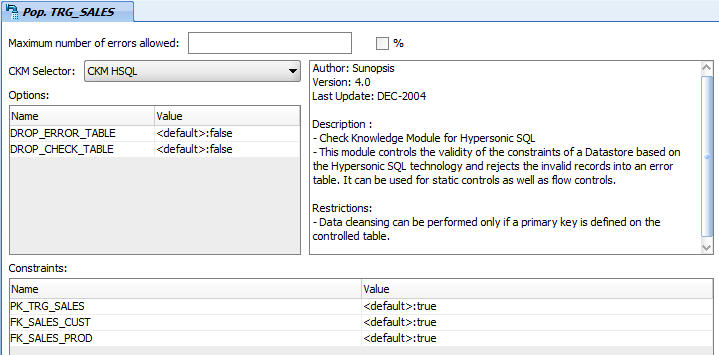
In the Controls tab of the Interface Editor, verify that the CKM HSQL is selected.
-
In the Constraints section, set the constraints that you wish to verify to
true:-
PK_TRG_SALES
-
FK_SALES_CUST
-
FK_SALES_PROD
The Controls tab appears as shown in Figure 6-25.
-
-
From File main menu, select Save.
The Pop. TRG_SALES interface is now ready to be executed.
