18 Creating Complex Task Flows
This chapter describes how to use advanced features of task flows.
This chapter includes the following sections:
18.1 Introduction to Complex Task Flows
After creating a basic unbounded or bounded task flow and adding task flow activities to it, you can perform specialized tasks such as transaction management and reentry.
For basic information about using task flow activities, see Chapter 15, "Working with Task Flow Activities".
If you want to work with ADF regions, see Chapter 17, "Using Task Flows as Regions".
To work with parameters, see Chapter 16, "Using Parameters in Task Flows".
18.2 Using Initializers and Finalizers
An initializer is custom code that is invoked when a bounded task flow is entered. A finalizer is custom code that is invoked when a bounded task flow is exited via a task flow return activity or because an exception occurred. The finalizer is a method on a managed bean. Common finalizer tasks include releasing all resources acquired by the bounded task flow and performing cleanup before exiting the task flow.
You specify both the initializer and the finalizer as an EL expression for a method on a managed bean, for example:
#{pageFlowScope.modelBean.releaseResources}
There are two techniques for running initializer code at the beginning of the bounded task flow, depending on whether or not the task flow may be reentered via a browser back button:
-
No reentry via back button expected: Designate a method call activity as the default activity (first to execute) in the bounded task flow. The method call activity calls a custom method containing the intializer code. For more information, see Section 15.5, "Using Method Call Activities" and Section 22.4.5, "What You May Need to Know About the Browser Back Button and Navigating Through Records".
-
Back button reentry possible: Specify an intializer method using an option on the bounded task flow metadata. For more information, see Section 14.2, "Creating a Task Flow". Use this technique if you expect that a user may reenter the task flow using a browser back button. In such a case, the designated default activity for the bounded task flow may never be called, but a method designated using the Initializer method will.
18.3 Managing Transactions
A transaction is a persisted collection of work that can be committed or rolled back together as a group. You can use a bounded task flow to represent a transaction and to declaratively manage transaction boundaries. In the Fusion Order Demo application, the customer registration and employee registration task flows are both implemented with the use of task flow return activities. The Cancel button implements rollback in the task flows. The Register button on the reviewCustomerInfo.jsff and reviewEmployeeInfo.jsff page fragment files implements commit functionality.
An end user can navigate from the shopping cart to initiate a backorder request for an out-of-stock item. The backorder request application is implemented as a bounded task flow that initiates a new transaction upon entry.
Transaction options on the called bounded task flow specify whether a called bounded task flow should join an existing transaction, create a new one, or create a new one only if there is no existing transaction.
If the called bounded task flow is able to start a new transaction (based on the transaction option that you selected), you can specify whether the transaction will be committed or rolled back when the task flow returns to its caller. The commit and rollback options are set on the task flow return activity that returns control back to the calling task flow. The same task flow that starts a transaction must also resolve the transaction.
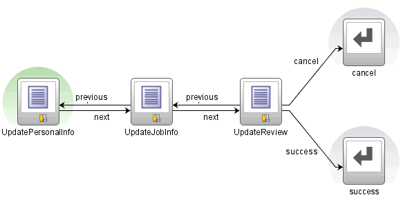
In a called bounded task flow, you can specify two different return task flow activities that result in either committing or rolling back a transaction in the called bounded task flow. Each of the task flow return activities passes control back to the same calling task flow. The difference is that one task flow return activity specifies the commit option, while the other specifies the rollback option. As shown in Figure 18-1, if transaction processing successfully completes, control flow passes to the success task flow return activity, which specifies options to commit the transaction. If the transaction is cancelled before completion, the cancel task flow activity specifies options to roll back the transaction.
If no transaction option is specified, a transaction is not started on entry of the called bounded task flow. A runtime exception is thrown if the bounded task flow attempts to access transactional services.
Use the restore-save-point option on the task flow return activity if you want to discard the changes an end user makes within a called bounded task flow when the called bounded task flow exits. ADF Controller rolls back to the previous ADF Model save point that was created when the bounded task flow was entered. The restore-save-point option applies only to cases when a bounded task flow is entered by joining an existing transaction (either the requires-existing-transaction or requires-transaction option is also specified) and a save point is created upon entry.
Tip:
You can use a return activity to call thecommit action or you can use a button bound to the commit action. If possible, use a task flow return activity. Using a task flow return activity will commit all data controls used by the ADF task flow. It also makes it easier to see where your application is doing commits and rollbacks, and is therefore easier to maintain.
-
You want to commit before the end of a task flow.
-
You are not using ADF Controller.
-
The task flow uses multiple data controls and you do not want to commit all of them.
18.3.1 How to Enable Transactions in a Bounded Task Flow
Define transaction options on a bounded task flow that is called by another task flow. Add a task flow return activity on the called bounded task flow that returns control to the task flow that calls the bounded task flow.
To enable a bounded task flow to run as a transaction:
-
In the overview editor for the called bounded task flow, click Behavior and expand the Transaction section.
-
Choose one of the following from the dropdown list:
-
<No Controller Transaction>: The called bounded task flow does not participate in any transaction management.
-
Always Use Existing Transaction: When called, the bounded task flow participates in an existing transaction already in progress.
-
Use Existing Transaction If Possible: When called, the bounded task flow either participates in an existing transaction if one exists, or starts a new transaction upon entry of the bounded task flow if one doesn't exist.
-
Always Begin New Transaction: A new transaction starts when the bounded task flow is entered, regardless of whether or not a transaction is in progress. The new transaction completes when the bounded task flow exits.
Note:
After choosing a transaction option, you may also need to select the Share data controls with calling task flow option for the bounded task flow to determine whether there are any interactions between the options. For more information, see Section 16.4.1, "What You May Need to Know About Managing Transactions." -
-
Optionally, deselect the Share data controls with calling task flow checkbox so that data controls are not shared with the calling task flow if you chose one of the following options in step 2:
-
Use Existing Transaction If Possible
-
Always Begin New Transaction
The default behavior is to share data controls. For more information, see Section 18.3.3, "What You May Need to Know About Data Control Scoping with Task Flows."
-
-
Optionally, select the No save point on task flow entry checkbox to prevent the creation of an ADF Model save point on task flow entry if you chose one of the following options in step 2:
-
Always Use Existing Transaction
-
Use Existing Transaction If Possible
An ADF Model save point is a saved snapshot of the ADF Model state. Selecting the No save point on task flow entry checkbox means that overhead associated with a save point is not created for the transaction.
-
-
Select the task flow return activity in the called bounded task flow.
-
In the Property Inspector, expand the Behavior section.
-
If the called bounded task flow supports creation of a new transaction (bounded task flow specifies Use Existing Transaction If Possible or Always Begin New Transaction options), select one of the following in the End Transaction dropdown list:
-
In the Restore Save Point dropdown list, select true if you want changes the user makes within the called bounded task flow to be discarded when the task flow exits. The save point that was created upon task flow entry will be restored.
18.3.2 What Happens When You Specify Transaction Options
Example 18-1 shows the metadata for transaction options on a called bounded task flow. The <new-transaction> element indicates that a new transaction always starts when the called bounded task flow is invoked.
Example 18-1 Called Bounded Task Flow Metadata
 <task-flow-definition id="trans-taskflow-definition">
    <default-activity>taskFlowReturn1</default-activity>
    <transaction>
      <new-transaction/>
    </transaction>
    <task-flow-return id="taskFlowReturn1">
      <outcome>
        <name>success</name>
        <commit/>
      </outcome>
    </task-flow-return>
  </task-flow-definition>
Example 18-1 also shows the metadata for transaction options on the task flow return activity on the called task flow. The <commit/> element commits the existing transaction to the database. The <outcome> element specifies a literal outcome, for example, success, that is returned to the caller when the bounded task flow exits. The calling ADF task flow can define control flow rules based on this outcome to For more information about defining control flow upon return, see Section 15.7, "Using Task Flow Return Activities."
18.3.3 What You May Need to Know About Data Control Scoping with Task Flows
The ADF Model layer exposes the DataControlFrame interface to manage a transaction in which the data controls within the frame participate. The DataControlFrame interface exposes methods such as:
-
beginTransaction() -
commit() -
rollback()
Similarly, ADF Controller allows a task flow to demarcate a transaction boundary, to begin a transaction at task flow entry, and to either commit or roll back the transaction on task flow exit. It does this by invoking methods exposed by the ADF Model layer's DataControlFrame interface.
ADF Controller supports the transaction options listed in Table 18-1. The behavior of these transaction options depends on whether you select or deselect the Share data controls with calling task flow checkbox (XML element: <data-control-scope>) in the overview editor for a task flow.
Table 18-1 Transaction Settings Behavior
| Transaction Setting | Share Data Control Scope | Isolate Data Control Scope |
|---|---|---|
|
<No Controller Transaction> |
The |
A new |
|
Always Begin New Transaction XML element: |
Begins a new transaction if one is not already open and throws an exception if one is already open. |
Always begins a new transaction. |
|
Always Use Existing Transaction XML element: |
Throws an exception if the transaction is not already open. |
Invalid. The checkbox cannot be deselected. |
|
Use Existing Transaction if Possible XML element: |
Begins a new transaction if one is not already open. |
Always begins a new transaction. |
18.4 Reentering a Bounded Task Flow
To deal with cases in which the end user clicks the back button to navigate back into a bounded task flow that was already exited, you can specify task-flow-reentry options for the bounded task flow. These options specify whether a page in the bounded task flow can be reentered.
Upon reentry, bounded task flow input parameters are evaluated using the current state of the application, not the application state existing at the time of the original bounded task flow entry.
Note:
Different browsers handle the back button differently. In order to ensure that back button navigation is properly detected across all browsers, the view activities within the task flow need to be properly configured. When a task flows uses thereentry-not-allowed or reentry-outcome-dependent option, the redirect attribute on each view activity within the task flow should be set to true. See Section 15.3, "Using URL View Activities" for more information on how to configure view activities.18.4.1 How to Set Reentry Behavior
You can set reentry behavior on a bounded task flow.
-
Open the bounded task flow in the overview editor.
-
Click Behavior.
-
In the Task Flow Reentry list, choose one of the following:
-
reentry-allowed: Reentry is allowed on any view activity within the bounded task flow.
-
reentry-not-allowed: Reentry of the bounded task flow is not allowed. If you specify
reentry-not-allowed on a bounded task flow, an end user can still click the browser back button and return to a page within the bounded task flow. However, if the user does anything on the page such as clicking a button, an exception (for example,InvalidTaskFlowReentry) is thrown indicating the bounded task flow was reentered improperly. The actual reentry condition is identified upon the submit of the reentered page.You can set up an exception handler to display the exception and route control flow in order to navigate to the default activity of the called bounded task flow. If the bounded task flow was not called from another bounded task flow, a normal web error is posted and handled as specified in the
web.xmlfile. -
reentry-outcome-dependent: Reentry of a bounded task flow using the browser back button is dependent on the outcome that was received when the same bounded task flow was previously exited via task flow return activities. If specified, any task flow return activities on the called bounded task flow must also specify either
reentry-allowedorreentry-not-allowedto define outcome-dependent reentry behavior.If you choose this option, the user can navigate to a task flow using a back button based solely on how the user originally exited the task flow. For example, a task flow representing a shopping cart can be reentered if the user exited by canceling an order, but not if the user exited by completing the order.
-
18.4.2 How to Set Outcome-Dependent Options
You can set outcome-dependent options on bounded task flows that have specified the reentry-outcome-dependent option, as described in Section 18.4.1, "How to Set Reentry Behavior."
To set outcome-dependent options:
-
In the task flow diagram for the bounded task flow, select the task flow return activity.
For information about adding a task flow return activity, see Section 15.7, "Using Task Flow Return Activities."
-
In the Property Inspector, expand the General section.
-
In the Name field, enter the name of literal outcome, for example,
successorfailure. -
Expand the Behavior section.
-
In the Reentry dropdown list, choose one of the following options:
-
reentry-allowed: Reentry is allowed on any view activity within the bounded task flow.
-
reentry-not-allowed: Reentry of the bounded task flow is not allowed. If you specify
reentry-not-allowed on a bounded task flow, an end user can still click the browser back button and return to a page within the bounded task flow. However, if the user does anything on the page such as clicking a button, an exception (for example,InvalidTaskFlowReentry) is thrown indicating the bounded task flow was reentered improperly. The actual reentry condition is identified upon the submit of the reentered page.You can set up an exception handler to display the exception and route control flow in order to navigate to the default activity of the called bounded task flow. If the bounded task flow was not called from another bounded task flow, a normal web error is posted and handled as specified in the
web.xmlfile.
-
18.4.3 What You Should Know About Managed Bean Values Upon Task Flow Reentry
When an end user reenters a bounded task flow using a browser's back button, and reentry is allowed, the value of a managed bean is reset to the value of the managed bean before the end user exited the bounded task flow. The managed bean value is reset before a view activity in the reentered bounded task flow renders. Any changes that occur before the reentry of the bounded task flow are lost. To change this behavior, specify the <redirect> element on the view activity in the reentered bounded task flow. When the end user reenters the bounded task flow using the back button, the managed bean has the new value from the parent task flow, not the original value from the child task flow that is reentered.
18.5 Executing a Bounded Task Flow Directly From a JSF Page
You can drag and drop a bounded task directly from the Application Navigator onto a JSF page. If the bounded task flow contains view activities that are page fragments, JDeveloper adds it to the JSF page as an ADF region. For example, the home page of the Fusion Order demo application contains a bounded task flow that displays a summary of items that the end user has added to a shopping cart page of the Fusion Order demo application. All view activities in the bounded task flow are page fragments, so the bounded task flow will be dropped on the Fusion Order demo application home page as a region. The contents of the shopping cart summary will display within a physical region on the home page of the Fusion Order demo application. For more information, see Chapter 17, "Using Task Flows as Regions".
However, if the bounded task flow contains view activities that are pages, JDeveloper proposes a choice of adding a task flow call as a button or a link. At runtime, end users can click the button or link to invoke the bounded task flow.
To add a bounded task flow containing pages to a JSF page:
-
In the Application Navigator, drag the source file for the ADF bounded task flow onto the page and drop it where you want to locate the button or link.
You can find task flows in the Application Navigator under the Page Flows or WEB-INF nodes.
-
Choose Create and either Task Flow Call as Button or Task Flow Call as Link.
As shown in Figure 18-2, the bounded task flow appears on the JSF page as either a button or link UI component.
18.6 Handling Exceptions
During execution of a task flow, exceptions can occur that may require some kind of exception handling, for example:
-
A method call activity throws an exception.
-
A custom method you have written as a task flow intializer or finalizer throws an exception.
-
A user is not authorized to execute the activity.
To handle exceptions thrown from an activity or caused by some other type of ADF Controller error, you can create an exception handler for a bounded or unbounded task flow.
When an exception is raised within the task flow, control flow passes to the designated exception handling activity. For example, the exception handling activity might be a view that displays an error message. Or the activity might be a router that passes control flow to a method based on an EL expression that evaluates the type of exception, for example, #{someException="oracle.adf.Controller.ControllerException"}.
After control flow passes to the error handling activity, flow from the activity uses standard control flow rules. For more information, see Section 14.1.3, "Control Flows".
You can optionally specify an exception handler for both ADF bounded and unbounded task flows. Each task flow can have only a single exception handler. However, a task flow called from another task flow can have a different exception handler from that of the caller. In addition, a region on a page can have a different exception handler from that of the task flow containing the page. The exception handler activity can be any supported activity type, for example, a view or router activity.
If a bounded task flow does not have a designated exception handler activity, control passes to an exception handler activity in a calling bounded task flow, if there is a calling task flow and if it contains an exception handler activity. The exception is propagated up the task flow stack until either an exception handler activity or the top-level unbounded task flow is reached. If no exception handler is found, the exception is propagated to the web container.
18.6.1 How to Designate an Activity as an Exception Handler
You can designate an exception handler activity for a bounded task flow running as an ADF region. If an exception occurs in the bounded task flow and it is not handled by the task flow's exception handler, the exception is not propagated up the task flow stack of the parent page. Instead, it becomes an unhandled exception.
To designate an activity as an exception handler for a task flow:
-
Right-click the activity in the task flow diagram, and choose Mark Activity > Exception Handler.
A red exclamation point is superimposed on the activity in the task flow to indicate that it is an exception handler. Figure 18-3 shows an example.
-
To unmark the activity, right-click the activity in the task flow diagram, and choose Unmark Activity > Exception Handler.
If you mark an activity as an exception handler in a task flow that already has a designated exception handler, the old handler is unmarked.
18.6.2 How to Handle Exceptions During Transactions
Designate an exception handling activity for a bounded task flow that is enabled to run as a transaction. A Fusion web application attempts to commit a transaction if you set commit as the value for a task flow return activity's End Transaction property on a bounded task flow that runs as a transaction. If an exception occurs when the Fusion web application attempts to commit a transaction, the exception handling activity receives control and provides the end user with an opportunity to correct the exception. You can use the exception handling activity (for example, a view activity) to display a warning message to an end user with information about how to correct the exception and how to recommit the transaction. For information about enabling a bounded task flow as a transaction and setting commit as a value for the End Transaction property, see Section 18.3.1, "How to Enable Transactions in a Bounded Task Flow."
18.6.3 What Happens When You Designate an Exception Handler
After you designate an activity to be the exception handling activity for a task flow, JDeveloper updates the task flow metadata with an <exception-handler> element that specifies the ID of the activity, as shown in Example 18-2.
18.6.4 What You May Need to Know About Handling Validation Errors
For validation errors on a JSF page, you can rely on standard JSF to attach validator error messages to specific components on a page or to the whole page. A component-level validator typically attaches an error message inline with the specific UI component. There is no need to pass control to an exception handler activity.
In addition, your application should define validation logic on data controls that are executed during the Validate Model Updates phase of the JSF lifecycle. In this way, data errors are found as they are submitted to the server without waiting until attempting the final commit.
Validations done during the Validate Model Updates phase typically do not have direct access to the UI components because the intention is to validate the model after the model has been updated. These validations are often things like checking to see whether dependent fields are in sync. In these cases, the error message is usually attached to the whole page, which this logic can access.
You should attach errors detected during the Validate Model Updates phase to the JSF page, and call FacesContext.renderResponse(). This signals that following this phase, the current (submitting) page should be rendered showing the attached error messages. There is no need to pass control to an exception handler activity.
For more information, see Chapter 8, "Implementing Validation and Business Rules Programmatically".
18.7 Adding Save Points to a Task Flow
You can configure a task flow to capture the state of a Fusion web application at a particular instance creating what is called a save point. This allows you to save application state if, for example, a user leaves a page without finalizing it. The application state can be restored at a later point.
Table 18-2 describes what information a save point captures.
Table 18-2 Saved Application State Information
| Saved State Information | Description |
|---|---|
|
User Interface State |
UI state of the current page, including selected tabs, selected checkboxes, selected table rows, and table column sort order. This state assumes the end user cannot select the browser back button on save point restore. |
|
Managed Beans |
State information saved in several possible memory scopes, including session and page flow scope. The managed beans must be serializable in order to be saved. If you have page flow scope beans that are not serializable and you attempt to create a save point, a runtime exception occurs. Request scope is not supported since its lifespan is a single HTTP request and its lifespan can't be used to store cross request application state. Save points will not save and restore application-scoped managed beans since they're not passivated in failover scenarios. Therefore, the application is always responsible for ensuring that all required application-scoped state is available. Potential naming conflicts for managed beans already existing within the session scope at restore time will not occur because multiple managed beans using the same name should not be implemented within an application. |
|
Navigation State |
Task flow call stack, which ADF Controller maintains as one task flow calls another at runtime. The task flow call stack tracks where the end user is in the application and the navigation path for getting there. The task flow stack also identifies the starting point of any persisted data transactions originated for the end user. |
|
ADF Model State |
Fusion web applications use ADF Model to represent the persisted data model and business logic service providers. The ADF Model holds any data model updates made from when the current bounded task flow begins. The model layer determines any limits on the saved state lifetime. For more information, see Chapter 40, "Application State Management". |
18.7.1 How to Configure Your Fusion Web Application to Use Save Points
Before you can add save points to a task flow and configure related functionality, you need to make sure that the Fusion web application allows save points. To do this, you define a value for the <savepoint-datasource> element in the adf-config.xml file to specify the save points' JNDI name for the database connection.
To configure your Fusion web application to allow save points:
-
With the Fusion web application open in JDeveloper, open the Application Resources pane in the Application Navigator.
-
Expand Descriptors, then expand ADF META-INF.
-
Right-click
adf-config.xmland choose Open from the context menu. -
On the Controller page of the overview editor, write a value for the Data Source property to specify a JNDI name for the data source.
For example, write the following:
java:comp/env/jdbc/Connection1DSwhere
Connection1is the JDeveloper connection name. -
Save the
adf-config.xmlfile.
18.7.2 What Happens When You Configure a Fusion Web Application to Use Save Points
JDeveloper generates an entry, similar to that illustrated in Example 18-3, in the adf-config.xml file to specify the save points' JNDI name for the database connection.
Example 18-3 Save Point Data Source Definition in adf-config.xml
<adf-controller-config xmlns="http://xmlns.oracle.com/adf/controller/config">
    ...
    <savepoint-datasource>
      java:comp/env/jdbc/Connection1DS
    </savepoint-datasource>
  </adf-controller-config>
For more information about the adf-config.xml file, see Section A.11, "adf-config.xml".
18.7.3 How to Add Save Points to a Task Flow
You add a method call activity to a bounded task flow that invokes a createSavePoint method to create save points. Later, you use a save point restore activity to restore application state and data associated with the created save points.
The same save point can be used if a user repeatedly performs a save for later on a task flow instance that executes in one session within the same browser window. The new save point overwrites the existing save point when a user performs a save for later following navigation from page to page in a task flow. For more information about restoring a save point, see Section 18.7.5, "How to Restore a Save Point".
You can specify the createSavePoint method exposed by the currentViewPort node of the ADF Controller Objects in the Expression Builder. Alternatively, you can write a custom method that updates the save point with the values of attributes you specify in your custom method, as illustrated in Example 18-4.
Example 18-4 Example Custom Method for Creating a Save Point
package viewController;

import java.io.Serializable;

import oracle.adf.controller.ControllerContext;
import oracle.adf.controller.savepoint.SavePointManager;

public class SaveForLater implements Serializable {
    public SaveForLater() {
        super();
    }

    public String saveTaskFlow() {
        ControllerContext cc = ControllerContext.getInstance();
        if (cc != null) {
            SavePointManager mgr = cc.getSavePointManager();
            if (mgr != null) {
                String id = mgr.createSavePoint();
                System.out.println("Save point is being set " + id);
            ...
Note:
A database table namedORADFCSAVPT is used to store a save point. If this database table does not exist, it is created the first time that a save point is created. The entry in ORADFCSAVPT for a save point is removed after the save point is restored.The SavePointListener interface exposes methods that notify clients when save point events occur. The following package contains the SavePointListener interface:
oracle.adf.controller.savepoint
Using a save point in a Fusion web application requires that you set the value of the jbo.locking.mode property to optimistic. The default value (pessimistic) causes an old session to lock until the session has timed out. For example, you run an application and change data without committing changes to the database. You may get an error when you create a save point and try to restore it at a later point. For information about changing the jbo.locking.mode property, see Section 9.3.4, "How to Change Your Application Module's Runtime Configuration".
To add a save point to a task flow:
-
Open the bounded task flow that you want to configure and navigate to the diagram editor.
-
In the ADF Task Flow page of the Component Palette, from the Components panel, drag a Method Call activity and drop it on the diagram for the bounded task flow.
-
In the Property Inspector, expand the General node and write an EL expression for the Method property to specify the save point method that the method call activity invokes.
If you use the Expression Builder to specify the
createSavePointmethod exposed by thecurrentViewPortnode of the ADF Controller Objects, the resulting EL expression is similar to the following:#{controllerContext.currentViewPort.createSavePoint} -
Use a control flow to connect the method call activity with other activities in the bounded task flow.
For more information, see Section 14.3.3, "How to Add Control Flows".
-
Optionally, configure save point options in the Fusion web application's
adf-config.xmlfile to determine, for example, if implicit save points can be created for the application.For more information, see Section 18.7.9, "How to Enable Implicit Save Points".
18.7.4 What Happens When You Add Save Points to a Task Flow
JDeveloper generates entries similar to those shown in Example 18-5 in the task flow's source file when you configure a method call activity to invoke the createSavePoint method.
18.7.5 How to Restore a Save Point
Use the save point restore activity to restore a previously persisted save point for an application. The save point restore activity uses the save point that was originally created by invoking the createSavePoint method to identify the save point to restore.
You can obtain a list of the current persisted save points with createSavePoint. However, ADF Controller does not determine which save points to restore. A user must select the save point from a list or the application developer must select it programmatically. The savepoint ID is then passed to a save point restore activity to perform the restore.
To add a save point restore activity to a bounded or unbounded task flow:
-
Open the bounded or unbounded task flow where you want to add the save point restore activity and navigate to the diagram editor.
-
In the ADF Task Flow page of the Component Palette, from the Components panel, drag a Save Point Restore activity and drop it on the diagram for the task flow.
-
In the Property Inspector, expand the General node and write an EL expression for the Save Point ID property that, when evaluated, retrieves the save point that was originally created when the
createSavePointmethod was invoked.If you use the Expression Builder to specify the
getSavePointmethod of the ADF Controller Objects, the resulting EL expression is similar to the following:#{SessionScope.myBean.savepointID}
18.7.6 What Happens When You Restore a Save Point
JDeveloper generates entries similar to Example 18-6 in the task flow's source file when you add a save point restore activity that gets a save point ID.
18.7.7 How to Use the Save Point Restore Finalizer
When using the save point restore activity, you may need to invoke application-specific logic as part of restoring the application state. You can write an EL expression for the Save Point Restore Finalizer property of a bounded task flow that specifies a finalizer method. The bounded task flow invokes the specified method after the task flow's state has been restored. It performs any necessary logic to make sure that the application's state is correct before proceeding with the restore.
To use the save point restore finalizer:
-
In the Structure window, right-click the node for the bounded task flow (
task-flow-definition) and select Go to Properties. -
In the Property Inspector, expand the General tab, and select Expression Builder from the dropdown menu displayed to the right of the Save Point Restore Finalizer property.
-
Write an EL expression that specifies the finalizer method to invoke.
18.7.8 What Happens When a Task Flow Invokes a Save Point Restore Finalizer
JDeveloper generates entries similar to Example 18-7 in the task flow's source file when you write an EL expression for the Save Point Restore Finalizer property.
18.7.9 How to Enable Implicit Save Points
A save point on a task flow can be categorized as implicit or explicit. An explicit save point requires an end user action before a bounded or unbounded task flow creates a save point. For example, an end user clicks a button that invokes a method call activity that, in turn, creates a save point.
An implicit save point can only originate from a bounded task flow. It includes everything from when the originating task flow creates a save point. It occurs when data is saved automatically because:
-
A session times out due to end user inactivity
-
An end user logs out without saving the data
-
An end user closes the only browser window, thus logging out of the application
-
An end user navigates away from the current application using control flow rules (for example, uses a
goLinkcomponent to go to an external URL) and having unsaved data.
Enabling implicit save points requires you to add an element to your Fusion web application's adf-config.xml file and to make the bounded task flow critical.
To enable implicit save points:
-
With the Fusion web application open in JDeveloper, open the Application Resources pane in the Application Navigator.
-
Expand Descriptors, then expand ADF META-INF.
-
Right-click
adf-config.xmland choose Open from the context menu. -
On the Controller page of the overview editor, select the Enable Implicit Savepoints checkbox.
JDeveloper generates the following entry in the
adf-config.xmlfile:<adf-controller-config xmlns="http://xmlns.oracle.com/adf/controller/config"> ... <enable-implicit-savepoints>true</enable-implicit-savepoints> </adf-controller-config>For more information about the
adf-config.xmlfile, see Section A.9, "adfc-config.xml". -
Open the bounded task flow in the overview editor.
-
Click the Behavior tab and select the Critical checkbox.
18.7.10 What You May Need to Know About Enabling Implicit Save Points
If multiple windows are open when the implicit save point is created, a different save point is created for each browser window. This includes everything from the root view port of the browser window on down. You can write an EL expression for the Method property of a method call activity to retrieve the list of implicit save points using the savePointManager node under ADF Controller Objects. The resulting EL expression is similar to the following:
ControllerContext.savePointManager.listSavePointIds
Implicit save points are generated only if a critical task flow is present in any of the page flow stacks for any view port under the current root view port. An implicit save point is not generated if the request is for an ADF Controller resource, such as:
-
Task flow call activity
-
Task flow return activity
-
Save point restore activity
-
A dialog
Implicit save points are deleted when the task flow at the bottom of the stack completes or a new implicit save point is generated, whichever comes earlier.
18.7.11 How to Set the Time-to-Live Period for a Save Point
An application-level property (save-point-expiration) that is defined in the adf-config.xml file determines the period between when a task flow creates a save point and when the save point manager removes it (time-to-live period). The default value is 86400 seconds (24 hours).
You can change the time-to-live period for individual save points by implementing the setSavePointTimeToLive method that is defined in the SavePointManger interface of the following package:
oracle.adf.controller.savepoint
Example 18-8 shows the syntax for the setSavePointTimeToLive method.
Example 18-8 Syntax for the setSavePointTimeToLive Method
    public void setSavePointTimeToLive(long timeInSeconds) {
       }
If you supply a value for the setSavePointTimeToLive method argument (timeInSeconds in Example 18-8) equal to or less than zero, the default value is used (86400).
Consider implementing the setSavePointTimeToLive method at the same time that you implement the method to create save points, as illustrated in Example 18-4.
18.8 Creating a Train
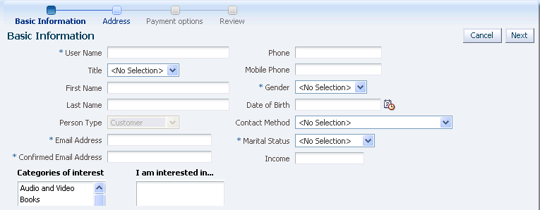
A train represents a progression of related activities that guides an end user to the completion of a task. The end user clicks a series of train stops, each stop linking to a particular page. Figure 18-4 shows a train in the Fusion Order demo application that is called when an end user clicks the Register as a customer link on the registration page.
This train contains four stops, each corresponding to a JSF page where the end user can enter and review registration information. The train stops are:
-
Basic Information
-
Address
-
Payment Options
-
Review
Each JSF page in the train contains an ADF Faces Train UI component similar to that shown in Figure 18-5. It enables the user to navigate through the train stops in an order specified in the underlying train model.
The optional Train Button Bar component shown in Figure 18-6 contains buttons that provide an additional means to navigate backwards and forwards though the stops. This component can be used in conjunction with the train component to provide multiple ways to navigate through train stops.
18.8.1 Bounded Task Flows as Trains
You can create a train based on activities in a bounded task flow that specifies the <train/> element in its metadata. You cannot create a train from activities in an unbounded task flow.
Tip:
You can also create a task flow template that has the<train/> element in its metadata, and then create a bounded task flow based on the template.Each bounded task flow can have a single train only. If the bounded task flow logically includes multiple trains, you must add each train to a separate bounded task flow.
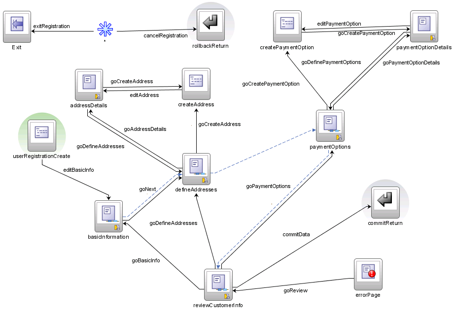
Figure 18-7 displays the bounded task flow that the Fusion Order Demo application uses to create the self-registration train shown in Figure 18-4.
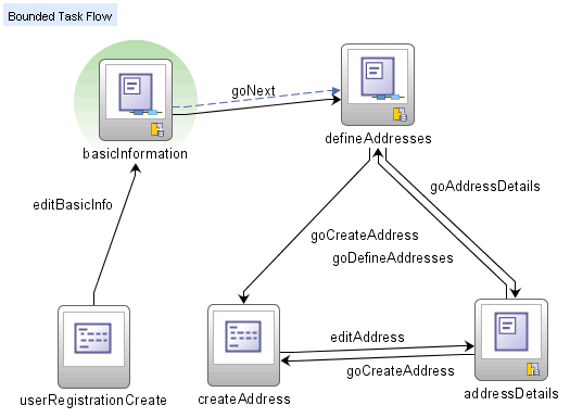
Figure 18-8 contains a simplified detail of the first two train stops in customer-registration-task-flow. In the figure, an icon (two blue circles) identifies each train stop in the train. The dotted line connecting each stop indicates the sequence in which the end user visits them. For more information, see Section 18.8.2, "Train Sequences". Although you can't drag the dotted line to change the sequence, you can right-click a train stop and choose options to move the train stop forwards or backwards in the sequence. Each train stop is usually a view activity corresponding to a JSF page, although you can also add use a task flow call activity as a train stop.
The task flow call activity is used to group sets of activities together as a train stop or to call a child train. For example, there are cases when other activities, such as router and method call activities, should be considered part of a train stop along with the corresponding view activity. A method call activity might need to precede a view activity for initialization purposes. When grouped this way, the activities can be performed as a set each time the train stop is visited. For more information, see Section 18.8.4, "What You May Need to Know About Grouping Activities".
Branching using router activities and control flow cases is supported on the task flow diagram containing the train, as well as in child bounded task flows called from the train. For more information, see Section 18.8.7, "What You May Need to Know About Branching".
18.8.2 Train Sequences
By default, train stops are sequential. A user can select a sequential train stop only after visiting the train stop that is before it in the sequence. A nonsequential train stop can be performed in any order.
A single train can contain both sequential and nonsequential stops. In Figure 18-9, the first step is the current train stop. Second stop is sequential because the user can click it only after visiting first stop. Third step is nonsequential because it can be clicked immediately after the user visits first stop without also having to visit second stop.
When first step is the current stop, the end user cannot click the fifth and sixth steps, indicating that they are sequential.
You can set the sequential option on the view activity (or task flow call activity) for each train stop to specify whether it has sequential or nonsequential behavior. The sequential option contains an EL expression that evaluates end-user input or some other factor, for example, #{myTrainModel.isSequential}. When the EL expression evaluates to true, the train stop behaves as sequential. When it evaluates to false, the train stop behaves as nonsequential.
In addition, you can alter the overall train sequence by skipping over individual train stops. The skip option on the activity corresponding to the train stop uses an EL expression that evaluates end-user input or some other factor to determine whether to skip over the train stop. If it evaluates to true, the train stop appears disabled and will be passed over. The end user is taken to the next enabled stop in the train. In addition, the train stop will be skipped if the end user clicks a Next or Previous button.
Note:
If you want the train to execute by default at some train stop other than the first one, use the skip option. For example, if you want the train to begin executing at train stop 3, specify skip on train stops 1 and 2. This is better than marking a view activity associated with a train stop as the default activity for the bounded task flow, which can cause unpredictable results. For more information, see Section 14.2.3, "What You May Need to Know About the Default Activity in an ADF Bounded Task Flow".18.8.3 How to Create a Train
To use a bounded task flow as a train, its metatdata must contain the <train/> element. There are several ways to include this element in the metadata:
-
Select the Create Train checkbox in the Create Task Flow dialog box. For more information, see Section 14.2, "Creating a Task Flow".
-
Select the Create Train checkbox in the Create ADF Task Flow Template dialog box and then use the template to create a new bounded task flow. For more information, see Section 18.10, "Creating a Task Flow Template".
-
Right-click an existing bounded task flow diagram in the editor and choose Train > Create Train.
-
Open an existing bounded task flow in the overview editor, click Behavior and select the Train checkbox.
-
In the editor, open a bounded task flow that is usable as a train.
You must include the
<train/>element in the bounded task flow's metadata by following one of the methods described above. -
Drag each view activity or JSF page you want to include in the train from the Application Navigator to the bounded task flow diagram.
-
If you drag a JSF page, JDeveloper automatically adds a view activity to the diagram.
-
If you drag a view activity, you can double- click it later to create a new JSF page.
Tip:
Don't worry about adding pages or view activities to the diagram in a particular order. You can adjust the train sequence later. -
-
To rearrange the order of train stops, right-click the stop corresponding to an activity in the diagram. Choose Train, and then choose a menu item to move the train stop within the sequence, for example, Move Forward or Move Backward.
-
By default, trains stops are sequential. You can optionally define whether the train stop behaves nonsequentially.
-
In the bounded task flow diagram, select the activity associated with the nonsequential train stop.
-
In the Property Inspector for the activity, click Train Stop.
-
In the sequential field, enter an EL expression, for example,
#{myTrainModel.isSequential}.You can also specify a literal value, for example,
true.If the EL expression evaluates to
true, the train stop will be sequential. Iffalse, the train stop will be nonsequential.
-
-
By default, a train stop will not be skipped. You can optionally designate that the train stop can be skipped based on the result of an EL expression.
-
In the bounded task flow diagram, select the activity associated with the nonsequential train stop.
-
In the Property Inspector, click Train Stop.
-
In the skip field, enter an EL expression, for example,
#{myTrainModel.shouldSkip}.If the EL expression evaluates to
true, the train stop will be skipped. Iffalse, the train stop will be not be skipped.
-
-
In the diagram, double-click each view activity that is being used as a train stop.
Double-clicking the view activity opens a dialog to create a new JSF page. If a JSF page is already associated with the view activity, the existing page displays.
-
Open the JSF page in the editor.
-
For each JSF page in the train, select a Train and, optionally, a Train Button Bar UI component from the Common Components section of the ADF Faces page of the Component Palette. Drag the UI component onto the JSF page.
The train and train button bar UI components are not automatically added to pages and page fragments corresponding to the view activities within a bounded task flow for a train. You must add them manually to each page or page fragment. You can also add them using a page template.
After you add the components to the page, they are automatically bound to the train model. For more information about creating a train model, see the Oracle Fusion Middleware Web User Interface Developer's Guide for Oracle Application Development Framework.
18.8.4 What You May Need to Know About Grouping Activities
Activities such as routers and method calls can be grouped with a view activity to form a single train stop. As shown in Figure 18-7, in the customer registration bounded task flow, the createAddress method call activity and the addressDetails view activity are grouped with the defineAddress view activity to create the second stop in the train. The activities are performed as a set each time the train stop is visited. createAddress validates user input on the Address page and defineAddress is an optional page where the end user can enter additional address information. Because the page is optional and is accessed using a link on the Address page, it is not included in the bounded task flow as a separate train stop. Instead, it is grouped as one of the activities for the createAddress train stop.
Note:
The approach for grouping a set of activities to form a train stop is to use a child bounded task flow (see Section 18.8.5, "What You May Need to Know About Grouping Activities in Child Task Flows"). The advantage of this approach is that all activities in the group are always performed together regardless of whether the train stop is being visited for the first time or on later returns.If you don't use a child bounded task flow, all activities from the leading nonview activity through the next view activity will be considered part of the train stop's execution.
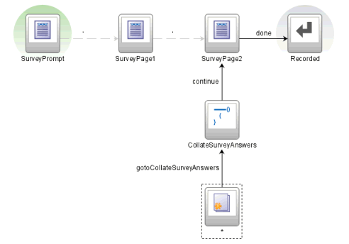
Although this approach groups a set of activities for a train stop within a child bounded task flow, you can provide the same functionality without a call to a child bounded task flow. Instead you can group the activities on the parent bounded task flow, as shown in Figure 18-10. All activities leading from the first nonview activity through the next view activity are considered part of the implied train stop's execution.
To group activities without a child bounded task flow, you must ensure that:
-
All non-view and non-task flow call activities for the train stop, such as routers and methods calls, follow the view or task flow call activity being used as the train stop.
This associates the activities with the train stop and not with the previous stop in the train.
-
A wildcard control flow leads to first activity of the train stop.
You must specify a value for
from-outcome(for examplegotoCollateSurveryAnswers) on the control flow leading from the wildcard control flow. This value must match the value you specify for the trainoutcomeon the view activity that is used as the train stop.The wildcard control flow ensures that if an end user returns to a previously visited train stop, all activities will be performed beginning with the activity the wildcard control flow points to.
In Figure 18-10, the SurveyPage2 train stop consists of the following group of activities that execute in the following order:
-
Wildcard control flow leading to first activity of the train stop,
CollateSurveyAnswers.Note:
The train stopoutcomeelement is used only if an activity such as a method call activity or router is placed prior to the view activity train stop. The element allows you to specify a custom outcome that results in navigation to the train stop. -
Method call to
CollateSurveyAnswers method. -
SurveyPage2view.
18.8.5 What You May Need to Know About Grouping Activities in Child Task Flows
You can also group related activities along with a corresponding view activity in a child bounded task flow. Then you can designate a task flow call activity as train stop in the train. For more information, see (Section 15.6, "Using Task Flow Call Activities". The task flow call activity calls the child bounded task flow. The group of activities are always performed together regardless of whether the train stop is being visited for the first time or on later returns.
Best practice:
When activities are grouped in a called child bounded task flow, nonview activities such as routers and methods calls typically precede the view activity in the control flow. You can include multiple view activities within the child bounded task flow, although in most cases there will be only one.
To group activities in the called child bounded task flow, you must ensure that:
-
All non view activities for the train stop, such as routers and methods calls, precede the view activity in the control flow of the child bounded task flow.
-
The child task flow contains a single view activity, unless the view activities are dialogs or helper pages originating from the main train stop view activity.
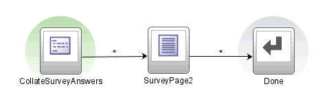
Figure 18-11 shows the SurveyTaskFlow train stop, a task flow call activity that calls a child bounded task flow.
The child bounded task flow is shown in Figure 18-21
All of the activities in the child bounded task flow are performed together every time the SurveyTaskFlow train is visited, regardless of whether the end user is visiting the first time or later.
If you use a child bounded task flow to group a set of activities, you must add a task flow return activity to the child task flow. The task flow return activity leads back to the parent bounded task flow, thus continuing the train. The task flow return activity should specify a value in outcome, for example, done, that will be used when returning to the parent train. In addition, you must manually add a control flow to the parent task flow that will be used to continue control flow within the train after returning from the child task flow.
As shown in Figure 18-11 and Figure 18-12, the value specified in the from-outcome for the control flow case (done) matches the task flow return activity outcome value.
18.8.6 What You May Need To Know About Using Child Trains
A train can use a task flow call activity as a train stop to invoke a child bounded task flow representing another train. The child bounded task flow must be created as its own train (that is, it must have the <train/> element in its metadata) and contain its own train stops. There is no limit to the depth of calls that are allowed to child trains.
18.8.7 What You May Need to Know About Branching
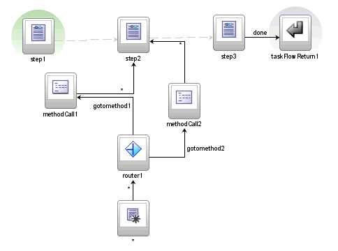
You can branch using router activities and control flow cases within a group of activities that are grouped to represent a single train stop, for example, the wildcard control flow rule router, and methods calls under step 2 in Figure 18-13.
You cannot branch between the activities that represent each train stop in a train. For example, you can not branch between steps 1, 2, and 3 in Figure 18-13.
18.9 Running Multiple Task Flows
Multiple task flows may run simultaneously within a Fusion web application and within the same HTTP session. In many cases, you can run each task flow in a separate browser window. For example a customer support representative might work multiple customer cases simultaneously, each within its own browser window.
Task flows can be initiated to display within new browser windows from either a request by the application or the browser.
-
Application requests new window
For example, the application itself requests a new browser window. This might occur when the end user clicks a button, a row in a table, or a link that results in a new browser window being launched. The UI component's JavaScript specifies the URL to load.
-
Browser requests new window
New browser windows can also be initiated when end users press Ctrl+N (Ctrl+T using Mozilla FireFox) or choose the File > New Window.
In Microsoft Internet Explorer, pressing Ctrl+N opens up the application home page as defined in the
web.xmlfile. The server state of the new window will be separate from the original window.
An application may also use different frames, multiple portlets, or ADF regions within a single browser window A view port describes the area that displays a view and its independent navigation. A view port can be in a full browser window, a frame, a portlet, or an ADF region.
Each view port maintains a task flow stack that represents an end user's current navigational state. A view port's task flow stack begins with the application's top-level task flow as the first entry on the stack. As the end user navigates into a bounded task flow, additional entries are pushed onto the stack representing the bounded task flow. As the end user navigates out of bounded task flows, entries are removed from the stack. If the end user navigates away from the parent page, any child modes and modal dialogs are closed.
Best Practice:
Although it is not necessary to notify the ADF Controller when a browser window is closed, it is at good design practice for the framework. This gives ADF Controller an opportunity to clean up resources allocated to the browser window's view port, such as managed beans and open, unresolved transactions.18.9.1 Understanding How the ViewPortInstance Works in ADF Regions
View ports can also be created when a page with a bounded task flow region is rendered. When a request for the first activity in a Fusion web application is received, ADF Controller creates a view port and a ViewPortContext corresponding to the main browser window. Each ADF region has an associated ViewPortContext instance. The ViewPortContext instance is created during the Restore View phase of the JSF lifecycle.
ADF Controller uses the ViewPortContext instance every time it needs to interact with JSF RI FacesContext. The ViewPortContext is responsible for dispatching all calls to FacesContext directly or to ADF view APIs. For example, when the ADF Controller finds a new view activity for the view port, it calls ViewPortContext.setRootViewId. For the bounded task flow representing the root page, this call results in calling FacesContext.setRootViewId. For bounded task flows embedded inside an ADF region, the ViewPortContext keeps track of the root view ID. When ADF View is ready to assemble the page markup for the root page, it can access the ADF region component's view ID stored on ViewPortContext.
For example, once a page containing ADF regions is rendered, an end user might click a button inside an ADF region causing a form submit:
-
ADF Controller handles the request in the context of a view port created for the ADF region.
-
The correct
ViewPortContextis set up by the ADF region before the ADF ControllerNavigationHandleris called. -
Based on
from-actionandfrom-outcomevalues, ADF Controller produces the ID of the next view activity for the bounded task flow region and sets it on theViewPortContext. -
ADF view will use the view activity ID in the Render Response stage of the JSF lifecyccle to pick up new markup for the ADF region. Because the NavigationHandler is called in the Region context, the root view ID for the main page is not be reset.
-
When the end user navigates away from the page, the bounded task flow region is destroyed. The view layer again notifies ADF Controller in order for resources allocated to the ADF region to be released.
18.10 Creating a Task Flow Template
You can create a task flow template that other developers can use as a starting point when creating new bounded task flows.
Note:
You cannot use a task flow template as the basis for creating a new unbounded task flow.The task flow template enables reuse because any bounded task flow based on it has the same set of activities, control flows, input parameters, and managed bean definitions that the template contains. In addition, you can specify that changes to the template be automatically propagated to any task flow or template that is created based on the template.
For example, suppose you have set up an activity to be used as an exception handler for a bounded task flow, such as a view activity associated with a page for global exception handling. Or, the exception handler might be set up to handle exceptions typically expected to occur in a task flow. If you expect multiple bounded task flows to rely on the same error handler, you might consider adding the error handler to a task flow template. New task flows created based on the template automatically have the error handling activity added to the template. See Section 18.6, "Handling Exceptions" for more information.
You can base a new task flow template on an existing task flow template. You can also refactor an existing bounded task flow to create a new task flow template. For more information, see Section 14.5.3, "How to Convert ADF Bounded Task Flows".
If you select the Update the Task Flow When the Template Changes checkbox in the Create ADF Task Flow or Create ADF Task Flow Template dialog, the template will be reused by reference. Any changes you make to the template will be propagated to any bounded task flow or task flow template based on it.
18.10.1 How to Copy and Reference a Task Flow Template
There are two methods for reusing a task flow templates.
-
Reuse by copy
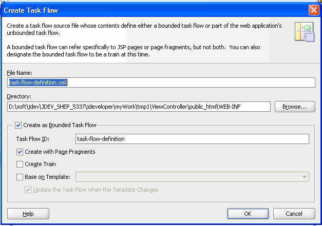
Deselect the Update the task flow when the template changes checkbox when creating a new bounded task flow, as shown in Figure 18-14. If you deselect the checkbox, the bounded task flow is independent of the template. Changes to the template are not propagated to the bounded task flow.
For example, if you add view activities associated with JSF pages to the template, the new bounded task flow will display the views and any control flows between them, and it will retain the view associations with JSF pages. If you add a train on a task flow template, any bounded task flow created from it contains page navigation for the train.
-
Reuse by reference
Select the Update the task flow when the template changes checkbox when creating a new bounded task flow, as shown in Figure 18-14, or when creating a new task flow template. Changes to the parent task flow template propagate to any bounded task flow or template based on it.
You can change, update, or disassociate the parent task flow template of a child bounded task flow or task flow template at any point during development of the child.
At runtime, the contents of a child bounded task flow or a child template reused by reference are combined additively with the contents of the parent template. Any collision between the parent template and child task flow or child template are won by the child. For example, suppose you created a parent task flow template containing a train, and then created a child bounded task flow based on the parent template. Later, you deselect the Train checkbox on the Behavior page of the overview editor for bounded task flows. The difference in how the Train checkbox is set for the parent template and the child task flow is a collision.
Table 18-3 describes the specific combination algorithm used for each element. As shown in the table, in the event of a collision between train settings, the child task flow overrides the parent task flow template.
Table 18-3 Collision Resolution between Parent Template and Children
| Bounded Task Flow Metadata | Combination Algorithm |
|---|---|
|
Default activity |
Child bounded task flow or child task flow template overrides parent task flow template. |
|
Transaction |
Child bounded task flow or child task flow template overrides parent task flow template as an entire block of metadata, including all subordinate elements. |
|
Task flow reentry |
Child bounded task flow or child task flow template overrides parent task flow template as an entire block of metadata, including all subordinate elements. |
|
Control flow rules |
Combination algorithm occurs at the control flow case level, not the control flow rule level. Control flow cases fall into the following categories:
Each of these categories is merged additively. The child bounded task flow or template overrides parent task flow template for identical matches within each of the four categories. |
|
Input parameter definitions |
Child bounded task flow or child task flow template overrides parent task flow template for identical input parameter definition names. |
|
Return value definitions |
Child bounded task flow or child task flow template overrides parent task flow template for identical return value definition names. |
|
Activities |
Child bounded task flow or child task flow template overrides parent task flow template for identical activity IDs. |
|
Managed beans |
Child bounded task flow or child task flow template overrides parent task flow template for identical managed bean names. |
|
Initializer |
Child bounded task flow or child task flow template overrides parent task flow template. |
|
Finalizer |
Child bounded task flow or child task flow template overrides parent task flow template. |
|
Critical |
Child bounded task flow or child task flow template overrides parent task flow template. |
|
Use page fragments |
Child bounded task flow or child task flow template overrides parent task flow template. |
|
Exception handler |
Child bounded task flow or child task flow template overrides parent task flow template. |
|
Security - permission |
Child bounded task flow or child task flow template overrides parent task flow template. Privilege maps are additive. Child bounded task flow or child task flow template overrides parent task flow template for identical privilege map operations. |
|
Security - transport guarantee |
Child bounded task flow or child task flow template overrides parent task flow template. |
|
Train |
Child bounded task flow or child task flow template overrides parent task flow template. |
Validations at both design time and runtime verify that the resulting parent-child extension hierarchy does not involve cycles of the same task flow template.
18.10.2 How to Create a Task Flow Template from Another Task Flow
The process for creating a new task flow template from an existing template is similar to the process for creating a bounded task flow based on a template. For more information, see Section 14.2, "Creating a Task Flow".
18.10.3 How to Use a Task Flow Template
After you create a task flow template, you can use it as the basis for creating a new bounded task flow or a new task flow template. As shown in Figure 18-14, the Create Task Flow dialog has fields for creating a bounded task flow based on the template file name and the ID. You must specify both the file name and ID of the template. These fields are available only if you select the Create as Bounded Task Flow checkbox.
You can base a new template on an existing template. The Create ADF Task Flow Template dialog box contains fields for creating a task flow template based on the file name and the template ID of an existing task flow template.
You cannot run a task flow template on its own. For more information, see Section 14.4, "Testing ADF Task Flows".
18.10.4 How to Create a Task Flow Template
The process for creating a new task flow template is similar to creating a bounded task flow. This section describes how to create a new task flow template. You can also convert an existing bounded task flow to a task flow template and vice versa. For more information, see Section 18.10.2, "How to Create a Task Flow Template from Another Task Flow".
To create a task flow template from scratch:
-
In the Application Navigation, right-click the project where you want to create the task flow and choose New.
-
In the New Gallery, expand
Web Tier. -
Select JSF, and then ADF Task Flow Template and click OK.
The value in File Name is used to name the XML source file for the task flow template you are creating. The source file includes the activities and control flow rules that are in the task flow template. The default name for the XML source file is
task-flow-template.xml. -
In the Create ADF Task Flow Template dialog, the Create with Page Fragments checkbox is selected by default. If you expect that a bounded task flow based on the template will be used as an ADF region, select this option.
If you want to add JSF pages instead of JSF page fragments to the task flow template, deselect the checkbox.
-
Click OK.
A diagram for the task flow template automatically opens in the editor.
-
You can add activities, control flows, and other items to the template.
Anything that you can add to a bounded task flow can be added to the task flow template.
-
When you are finished, save your work.
The template will be available for use when you create a bounded task flow or task flow template.
18.10.5 What Happens When You Create a Task Flow Template
As shown in Example 18-9, an XML file is created each time you create a new task flow template using JDeveloper. You can find the XML file in the Application Navigator in the location that you specified in the Directory field of the Create ADF Task Flow Template dialog, for example,.../WEB-INF.
The contents of the XML source file for the task flow template can be similar to those of a bounded task flow. One difference is the inclusion of the <task-flow-template> tag.
Example 18-9 Task flow template source file
<?xml version="1.0" encoding="windows-1252" ?>
<adfc-config xmlns="http://xmlns.oracle.com/adf/controller" version="1.2" id="__1">
  <task-flow-template id="task-flow-template">
     <default-activity>view1</default-activity>
     <view id="view1">view1.jsff</view>
  </task-flow-template>
</adfc-config>
18.10.6 What You May Need to Know About Task Flow Templates That Use Bindings
If you use a task flow template that contains bindings, you must change the component IDs of task flows based on the task flow template. Doing this ensures that the IDs are unique. Task flows generated from the template inherit the same ID as the template. This may cause an exception at runtime.
For more information, see Section 20.2.1, "How to Use ADF Data Binding in ADF Page Templates".
18.11 Creating a Page Hierarchy
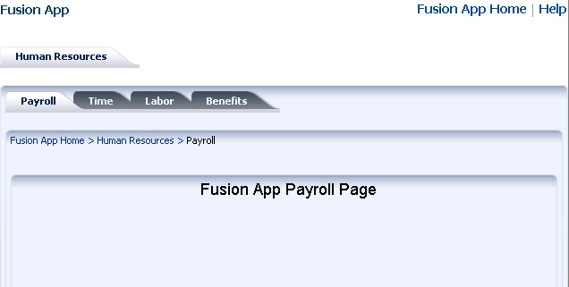
Creating a page hierarchy is a useful way of organizing the JSF pages in your Fusion web application so that end users can more easily navigate the application. End users access information on the pages by navigating a path of links. Figure 18-15 shows a sample page hierarchy.
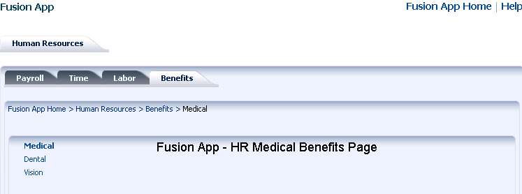
To navigate this hierarchy, an end user clicks links on each page to drill down or up to another level of the hierarchy. For example, clicking Human Resources on the Fusion App home page displays the Human Resources page hierarchy shown in Figure 18-15. Clicking the link on the Benefits tab displays the page hierarchy shown in Figure 18-16.
The user can click links on the Benefits page to display other pages, for example, the Medical, Dental or Vision pages. The breadcrumbs on each page indicate where the current page fits in the hierarchy. The user can click each node in a breadcrumb to navigate to other pages in the hierarchy. The bold tab labels match the path to the current page shown the breadcrumbs.
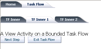
Pages referenced by view activities in a bounded task flow can also be included in any page hierarchy that you generate. Figure 18-17 shows the runtime view of a page hierarchy that renders view activities referenced by a bounded task flow.
You can use ADF Controller with an XMLMenuModel implementation to create the previously-discussed page hierarchies. If you do, JDeveloper generates the following for you:
-
Control flow metadata that determines the view or page to display when an end user selects a menu item
-
An
XMLMenuModelmetadata file -
Default navigation widgets such as Previous and Next button
-
Breadcrumbs
-
Managed bean configuration
If you decide not to use ADF Controller, you can create the page hierarchy using an XMLMenuModel implementation. For more information about this method of building a page hierarchy, see the "Using a Menu Model to Create a Page Hierarchy" section in the Oracle Fusion Middleware Web User Interface Developer's Guide for Oracle Application Development Framework.
18.11.1 How to Create a Page Hierarchy
Create an unbounded task flow or open an existing one. Add view activities or bounded task flows to the unbounded task flow. Each view activity or bounded task flow that you add to the unbounded task flow contains references to pages to appear in the proposed page hierarchy. Use JDeveloper's Create ADF Menu Model dialog to generate an XMLMenuModel metadata file. Organize the item nodes in the generated XMLMenuModel metadata file to create the page hierarchy you want. Connect submenus to parent menus to finalize the hierarchy.
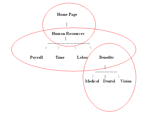
Figure 18-18 shows an example page hierarchy that consists of view activities:
-
The top-level menu (Home Page) is the root parent page. It contains a single tab that links to the Human Resources submenu.
In JDeveloper, Home Page page is represented as an item node and Human Resources page as a shared node.
-
Human Resources has four tab links to Payroll, Time, Labor, and Benefits pages.
In this menu, Human Resources is a group node that references child item nodes (Payroll, Time, and Labor) and a shared node (Benefits) that references the Benefits submenu.
-
Benefits is a group node that references child item nodes (Medical, Dental, and Vision) pages.
Note:
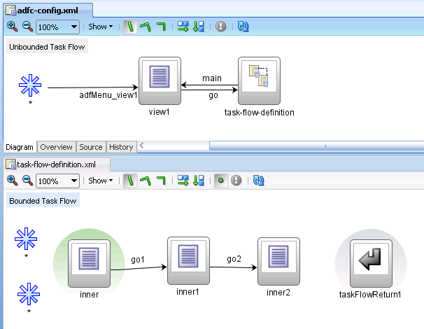
It is possible to create the entire menu hierarchy in one menu model. However, breaking a menu hierarchy into submenus makes maintenance easier. In addition, breaking the menu hierarchy into smaller submenu models enables each separate development organization to develop its own menu. These separate menus can later be combined using shared nodes to create the complete menu hierarchy.Figure 18-19 shows the corresponding design-time view in JDeveloper of the unbounded and bounded task flows that render the page hierarchy shown in Figure 18-17. The unbounded task flow (adfc-config.xml) contains a view activity (view1) and a task flow call activity (task-flow-definition) that invokes the bounded task flow (task-flow-definition.xml) shown in the lower part of Figure 18-19.
18.11.1.1 How to Create an XMLMenuModel Metadata File
You use JDeveloper's Create ADF Menu Model dialog to generate an XMLMenuModel metadata file once you have defined what menus (unbounded task flows) and nodes (pages) you want to appear in the final page hierarchy.
To create the XMLMenuModel metadata file:
-
Create an unbounded task flow for each menu in the final page hierarchy.
For example, to achieve the page hierarchy illustrated in Figure 18-18, you create two unbounded task flows (Human Resources menu and Benefits menu).
For more information about creating an unbounded task flow, see Section 14.2.1, "How to Create a Task Flow".
Tip:
Prefix the name of the file for unbounded task flows that you create withadfc-to help you to identify the file as the source of an unbounded task flow, as opposed to a bounded task flow. -
Add view activities that reference pages to each unbounded task flow. The pages referenced by the view activities correspond to the menu nodes in the menu.
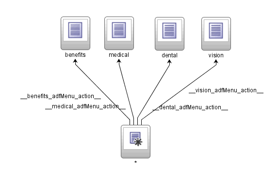
For example, the Benefits menu contains one group node (benefits) and three item nodes (medical, dental and vision) so you add four view activities to the unbounded task flow for the Benefits menu, as illustrated in Figure 18-20.
Do not add view activities for menus that include other menus using shared nodes. For example, the Human Resources menu in Figure 18-18 has a tab called Benefits that references the Benefits menu using a shared node. The bounded task flow for the Benefits menu already includes a view activity for Benefits so there is no need to add a view activity to the bounded task flow for the Human Resources menu.
For more information about adding view activities, see Section 15.2.1, "Adding a View Activity".
Note:
If the page hierarchy includes pages referenced by a bounded task flow, add a task flow call activity to the unbounded task flow that calls the bounded task flow. -
In the Application Navigator, right-click the file(s) for each of the unbounded task flows you created in step 1 and choose Create ADF Menu Model.
-
In the Create ADF Menu Model dialog, enter a file name for the
XMLMenuModelmetadata file and a directory to store it. -
Click OK.
18.11.1.2 How to Create a Submenu with a Hierarchy of Group and Child Nodes
You open the XMLMenuModel metadata file you created and convert the item nodes that you want to make group nodes to group nodes. You then create a hierarchy where a group node is a parent to one or more item nodes.
To create a submenu with a hierarchy of group and item nodes:
-
In the Application Navigator, select and open the
XMLMenuModelmetadata file.An item node appears in the Structure window for each view activity in the unbounded task flow. By default, no hierarchy is defined.
-
Drag and drop the item nodes to become child nodes of the item node that you are going to convert to a group node.
Each item node that you convert to a group node must have at least one child item node. For example, to create the menu hierarchy in Figure 18-18, you convert the item node for Benefits to a group node, you drag and drop the item nodes for Medical, Dental, and Vision so that they become child nodes of the Benefit item node.
-
In the Structure window, right-click the parent item node and choose Convert To groupNode.
-
Enter a new identifier or accept the default value in the id field of the groupNode Properties dialog that appears
The identifier must be unique among all of the nodes in all of the
XMLMenuModelmetadata files. It is good practice to specify a value that identifies the node. For example, if you change the Benefits node to a group node, you can update its default ID,itemNode_benefits, togroupNode_benefits. -
In the idref field of the groupNode Properties dialog, enter the ID of one of the other nodes in the menu, for example,
itemNode_Medical.The value you enter can be an ID of a child item node that is a group node or an item node.
-
Enter or change the existing default value in the label field to match what you want to appear at runtime.
For example, you might change
label_benefitstoBenefits. -
Accept the rest of the default values in the fields and click Finish
A Confirm Convert dialog asks if you want to delete the
actionandfocusViewIDattributes on thegroupNodeelement. Group nodes do not use these attributes, always click OK -
Click OK
18.11.1.3 How to Attach a Menu Hierarchy to Another Menu Hierarchy
You use a shared node element to link two menus together. For example, the Human Resources menu illustrated in the menu hierarchy in Figure 18-18 contains four submenus (Payroll, Time, Labor, and Benefits). The Benefits submenu is itself a menu with submenu entries. In the XMLMenuModel metadata file for the Human Resources menu, you convert the item node for the Benefits submenu to a shared node. You write an EL expression for an attribute (ref) of the newly-created shared node that references the XMLMenuModel metadata file for the Benefits menu.
To attach a menu hierarchy to another hierarchy using a shared node:
-
In the Application Navigator, select and open the
XMLMenuModelmetadata file for the menu that is going to reference the other menu. -
In the Structure window, select a node, right-click and select the appropriate menu options to insert a
sharedNodeelement. -
In the ref field of the Insert sharedNode dialog that appears, enter an EL expression to reference the
XMLMenuModelmetadata file for the other menu. -
Click OK.
Note:
If your page hierarchy has more than one unbounded task flow, ensure that the file name for each additional unbounded task flow appears as a value for the<metadata-resources>element in theadfc_config.xmlfile. For more information, see Section 18.11.2, "What Happens When You Create a Page Hierarchy".
18.11.2 What Happens When You Create a Page Hierarchy
Changes occur in a number of different files when you create a page hierarchy.
Changes to the adfc-config.xml File
When you create a new unbounded task flow, JDeveloper automatically adds a reference in the adfc-config.xml file to the source file for the newly-created unbounded task flow. In Example 18-10, adfc-unbounded_tflow.xml is the name of the source file for a newly-created unbounded task flow.
Example 18-10 Unbounded task flow referenced by adfc-config.xml
<?xml version="1.0" encoding="windows-1252" ?>
<adfc-config xmlns="http://xmlns.oracle.com/adf/controller" version="1.2"
             id="__1">
  <metadata-resource id="__2">/WEB-INF/adfc-unbounded_                tflow.xml</metadata-resource>
</adfc-config>
For more information about adfc-config.xml, see Section A.9, "adfc-config.xml".
At runtime, the Fusion web application loads the adfc-config.xml file when it first starts. The adfc-config.xml file can contain:
-
ADF navigation metadata for an unbounded task flow
-
ADF activity metadata for an unbounded task flow
-
Managed bean definitions used by ADF activities
JDeveloper generates an XMLMenuModel metadata file with nodes for each of the view activities that you added to the unbounded task flow, as illustrated in Example 18-2.
Example 18-11 Example XMLMenuModel Metadata File
<?xml version="1.0" encoding="windows-1252" ?>
<menu xmlns="http://myfaces.apache.org/trinidad/menu">
  <groupNode id="groupNode_benenfits" label="Benefits" idref="itemNode_medical">
    <itemNode id="itemNode_medical" label="label_medical"
              action="adfMenu_medical" focusViewId="/medical"/>
    <itemNode id="itemNode_dental" label="label_dental" action="adfMenu_dental"
              focusViewId="/dental"/>
    <itemNode id="itemNode_vision" label="label_vision" action="adfMenu_vision"
              focusViewId="/vision"/>
  </groupNode>
</menu>
Diagram for an Unbounded Task Flow
JDeveloper updates the file for the unbounded task flow with the control flow rules and managed beans used to navigate the page hierarchy. Figure 18-21 shows the updated unbounded task flow in the diagrammer that corresponds unbounded task flow in Figure 18-20.
18.12 Using BPEL with Task Flows
Business Process Execution Language (BPEL) is a language for composing multiple services into an end-to-end business process. You can use BPEL with task flows to:
-
Invoke a BPEL process from an unbounded or bounded task flow to perform a function or use services
-
Call a bounded task flow from the BPEL process manager in order to model user interactions with a web interface
For more information about BPEL, see the Oracle Fusion Middleware Developer's Guide for Oracle SOA Suite.
18.12.1 How to Invoke a BPEL Process from a Task Flow
You can use any of the following techniques for calling a BPEL process from an unbounded or bounded task flow:
-
Bind an existing method call activity on the task flow diagram to a managed bean method wrapping the BPEL process call as a Java component. For more information, see Section 15.5, "Using Method Call Activities".
-
Bind an existing method call activity on the task flow diagram to an action binding performing the BPEL process call as a web service For more information, see Section 15.5, "Using Method Call Activities"for more information. The web service data control is the preferred approach to use when calling as a Web Service.
During runtime, the application will place the request to the BPEL process in the form of a payload. The BPEL process receives the payload and responds with a payload containing the information the application requested. The BPEL process outcome is to continue control flow in the unbounded or bounded task flow.
18.12.2 How to Call a Bounded Task Flow from BPEL
BPEL workflow services allow human interactions to be interspersed between tasks within end-to-end flows. During a BPEL process flow, a task is assigned to a user or role and then it waits for a response. The user will act on the task using the BPEL worklist application. The worklist application is able to initiate a bounded task flow assigned as part of the user's task. Bounded task flow functionality can be used while still taking advantage of the human interaction framework of a BPEL process (for example, notifications, escalation policy, and worklist).
