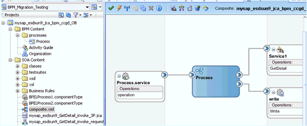
1 General Upgrade Guidelines
This chapter lists and describes general upgrade guidelines that are common to all Oracle Application Adapters for Oracle WebLogic Server. It contains the following topics:
-
Migrating Oracle Service Bus 10.1.3.x/PS2 Outbound and Inbound Processes to 11g PS3
-
Upgrading 11g PS1/PS2 Outbound and Inbound BPEL and Mediator Processes to 11g PS3
-
Upgrading 11g PS2 Outbound and Inbound BPM Processes to 11g PS3
Upgrading a 10.1.3.x Outbound Process to 11g
This section describes how to upgrade a 10.1.3.x outbound process to 11g.
Note:
For demonstration purposes, Oracle Application Adapter for SAP R/3 is used as an example.The 10.1.3.x BPEL and Mediator projects for the application adapters should not have any warning or error messages during compilation and deployment with 10.1.3.x version. If any warning or error messages are present, then they must be corrected before migrating the projects to 11g. If you have followed the 10.1.3.x user guides for creating a BPEL or Mediator project, then you would see two warning messages in Oracle JDeveloper at the time of compilation deployment. These warning messages are not acceptable in the 11g environment. Those warning messages are shown because the assign statements were assigning the BPEL/ESB project namespace to the adapter's namespace. This is an incompatible namespace assignment. As a result, any warning or error messages in 10.1.3.x projects must be corrected before migrating to 11g. This section describes how to create 10.1.3.x projects without the warning messages.
Prerequisites
Take a note of the adapter targets and channels that were created in the 10.1.3.x Application Explorer for your application adapters. For the migration to be successful, you must create the same adapter targets and channels in the 11g environment using the Application Explorer.
Before continuing, ensure that the following components are available:
-
Using Application Explorer, export the schemas for a particular business object for Oracle Application Adapter for SAP R/3 into the default location.
-
Using Application Explorer, generate a JCA outbound WSDL for a particular business object for Oracle Application Adapter for SAP R/3.
Overview of 10.1.3.x BPEL JCA Outbound Workflow Process
-
Create an outbound BPEL process project.
-
Configure an outbound BPEL process.
-
Deploy the outbound BPEL process project.
-
Invoke the input XML using the BPEL console.
Creating an Outbound BPEL Process Project
To create an outbound BPEL process project:
-
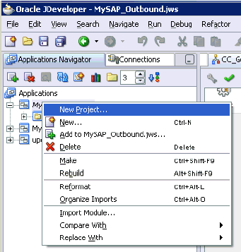
As shown in Figure 1-1, start Oracle JDeveloper 10.1.3.4.
-
Click the Application Navigator tab and select New Project from the context menu.
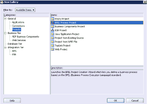
The New Gallery dialog is displayed, as shown in Figure 1-2.
-
Select the BPEL Process Project and then click OK.
The BPEL Project Creation Wizard - Project Settings page is displayed, as shown in Figure 1-3.
Figure 1-3 BPEL Project Creation Wizard - Project Settings Page
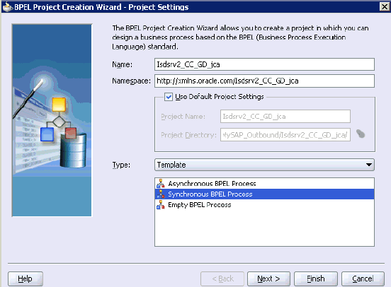
Description of "Figure 1-3 BPEL Project Creation Wizard - Project Settings Page"
-
Enter a name for the new BPEL process project in the Name field.
-
Select Synchronous BPEL Process from the Template Type list and click Next.
The BPEL Project Creation Wizard - I/O Elements page is displayed, as shown in Figure 1-4.
Figure 1-4 BPEL Project Creation Wizard - I/O Elements Page
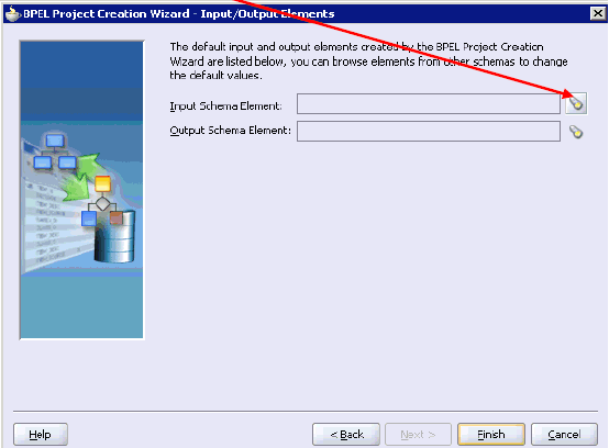
Description of "Figure 1-4 BPEL Project Creation Wizard - I/O Elements Page"
-
Click the Browse icon to the right of the Input Schema Element field.
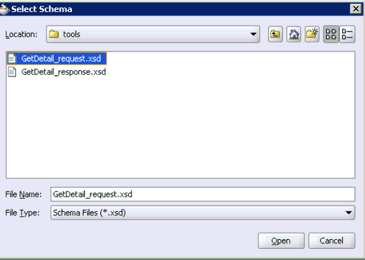
The Select Schema dialog is displayed, as shown in Figure 1-5.
-
Navigate to the default exported schema location:
<soadp1>\adapters\application\tools
-
Select the request XML schema file (.xsd) for the corresponding business object and click Open.
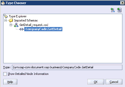
The Type Chooser dialog is displayed, as shown in Figure 1-6.
-
Expand Imported Schemas, the request XML schema (for example, GetDetail_request.xsd), and then the method (for example, CompanyCode.GetDetail).
-
Click OK.
You are returned to the BPEL Project Creation Wizard - I/O Elements page, as shown in Figure 1-7.
Figure 1-7 BPEL Project Creation Wizard - I/O Elements Page
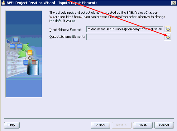
Description of "Figure 1-7 BPEL Project Creation Wizard - I/O Elements Page"
-
Click the Browse icon to the right of the Output Schema Element field.
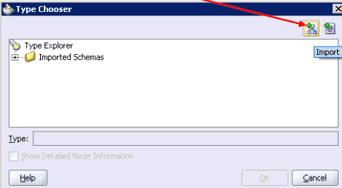
The Type Chooser dialog is displayed, as shown in Figure 1-8.
-
Click the Import Schema icon.
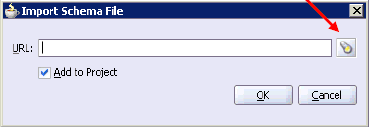
The Import Schema File dialog is displayed, as shown in Figure 1-9.
-
Click the Browse icon.
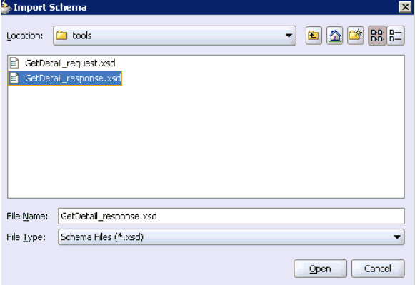
The Import Schema dialog is displayed, as shown in Figure 1-10.
-
Navigate to the default exported schema location:
<soadp1>\adapters\application\tools
-
Select the response XML schema file (.xsd) for the corresponding business object and click Open.
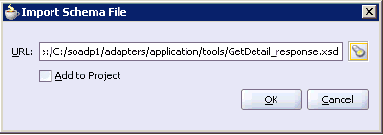
You are returned to the Import Schema File dialog, as shown in Figure 1-11.
-
Uncheck the Add to Project option.
-
Click OK.
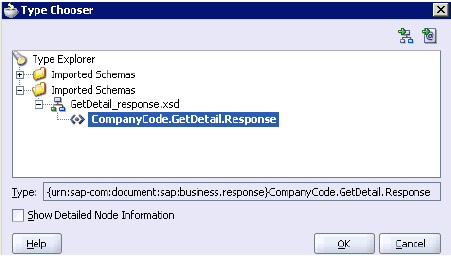
The Type Chooser dialog is displayed, as shown in Figure 1-12.
-
Expand Imported Schemas, the response XML schema (for example, GetDetail_response.xsd), and then the method (for example, CompanyCode.GetDetail.Response).
-
Click OK.
You are returned to the BPEL Project Creation Wizard - I/O Elements page, as shown Figure 1-13.
Figure 1-13 BPEL Project Creation Wizard - I/O Elements Page
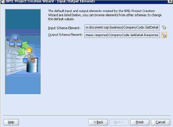
Description of "Figure 1-13 BPEL Project Creation Wizard - I/O Elements Page"
-
Click Finish.
Figure 1-14 Standard BPEL Outbound Process
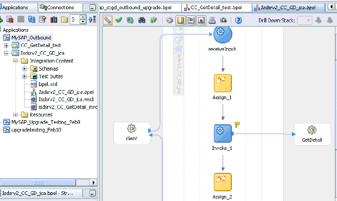
Description of "Figure 1-14 Standard BPEL Outbound Process"
-
Continue with the creation of a standard BPEL outbound process using Partnerlink, Invoke, and Assign components.
-
Compile the outbound BPEL process project, as shown in Figure 1-15.
Figure 1-15 Outbound BPEL Process Project

Description of "Figure 1-15 Outbound BPEL Process Project"
-
Verify that there are no error or warning messages during compilation.
-
Deploy the outbound BPEL process project.
-
After the deployment is successful, go to the BPEL console and execute the deployed process.
A successful response is received.
Migrating the 10.1.3.x BPEL JCA Outbound Process to a 11g Workflow Process
This section describes how to migrate the 10.1.3.x BPEL JCA outbound process to a 11g workflow process.
Note:
For demonstration purposes, Oracle Application Adapter for SAP R/3 is used as an example.Prerequisites
Before continuing, ensure that you copy and paste the 10.1.3.x outbound BPEL Process Project to the 11g system location.
Overview of Migration to 11g BPEL JCA Outbound Workflow Process
-
Open an application.
-
Migrate the 10.1.3.x BPEL JCA outbound process to 11g.
-
Deploy the BPEL process project.
-
Invoke the input XML using the Oracle Enterprise Manager console.
Migrating an Outbound BPEL Process Project
To migrate an outbound BPEL process project:
-
Start Oracle JDeveloper 11g, as shown in Figure 1-16.
Figure 1-16 Open Icon in Oracle JDeveloper 11g
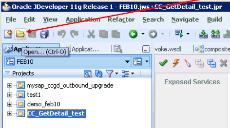
Description of "Figure 1-16 Open Icon in Oracle JDeveloper 11g"
-
Select an available application (for example, FEB10) and click Open from the tool bar.
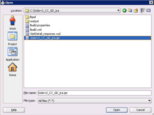
The Open dialog is displayed, as shown in Figure 1-17.
-
Open the 10.1.3.x project (for example, Isdsrv2_CC_GD_jca) and select the .jpr extension file (for example, Isdsrv2_CC_GD_jca.jpr).
-
Click Open.
The Migration Wizard is displayed, as shown in Figure 1-18.
Figure 1-18 Welcome Page of the Migration Wizard
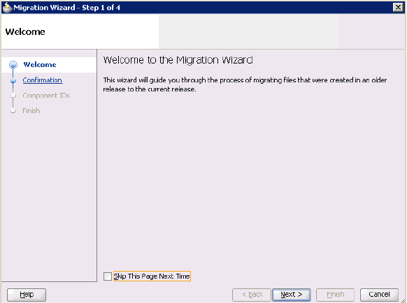
Description of "Figure 1-18 Welcome Page of the Migration Wizard"
-
Click Next.
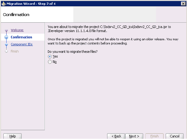
The Confirmation page is displayed, as shown Figure 1-19.
-
Verify that Yes is selected (default) and click Next.
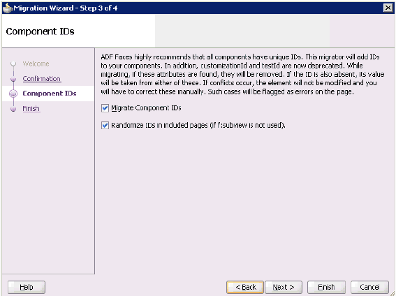
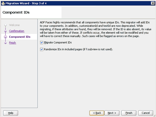
The Component IDs page is displayed, as shown in Figure 1-20.
-
Accept the default values and click Next.
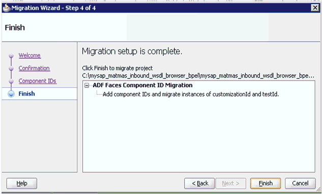
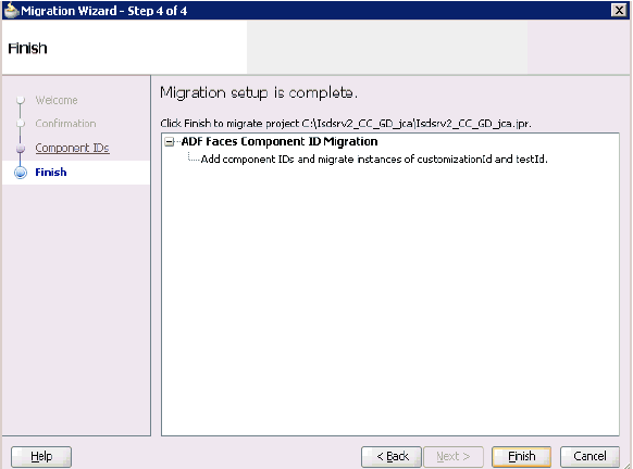
The Finish page is displayed, as shown in Figure 1-21.
Figure 1-21 Finish Page of the Migration Wizard
Description of "Figure 1-21 Finish Page of the Migration Wizard"
-
Click Finish. The following message is displayed, as shown in Figure 1-22.
Figure 1-22 Successful Migration Status Message

Description of "Figure 1-22 Successful Migration Status Message"
-
Click OK.
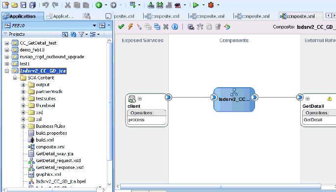
As shown in Figure 1-23, the 10.1.3.x project is now available in your 11g environment.
Figure 1-23 A Migrated 10.1.3.x Project in the 11g Environment
Description of "Figure 1-23 A Migrated 10.1.3.x Project in the 11g Environment"
-
Expand the migrated project in the left page (for example, Isdsrv2_CC_GD_jca) and double-click the composite.xml file to verify that the project opens without any errors.
-
Click Save.
-
Compile and then deploy the migrated BPEL process project, as shown in Figure 1-24.
-
Verify that there are no error or warning messages during compilation and deployment.
-
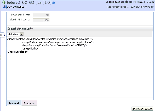
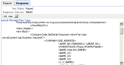
After the deployment is successful, as shown in Figure 1-25, go to the Oracle Enterprise Manager console and execute the deployed process either in Tree View or XML View and get the successful response.
Input XML in XML View
Output XML that is received
Figure 1-26 Output XML Received in the Response Tab
Description of "Figure 1-26 Output XML Received in the Response Tab"
Post-Upgrade Requirement
The following changes must be made for every outbound ESB and BPEL process after the corresponding project is migrated to 11g.
-
Expand the migrated project and double-click the composite.xml file.
-
Click source.
-
Navigate to the
referencesection, check for the .jca file that has the naming convention asxxxx_iway.jcaand replace withxxxx_iway_3P.jca(adding _3P as a suffix).Original:
<reference ui:wsdlLocation="isdsrv15_eaicreate_node_invoke.wsdl" name="create_node"><interface.wsdl interface="http://xmlns.oracle.com/pcbpel/iWay/wsdl/Siebel/isdsrv15/create_node#wsdl.interface(create_nodePortType)" xmlns:ns="http://xmlns.oracle.com/sca/1.0"/><binding.jca config="create_node_iway.jca"/></reference>Modified:
<reference ui:wsdlLocation="isdsrv15_eaicreate_node_invoke.wsdl" name="create_node"><interface.wsdl interface="http://xmlns.oracle.com/pcbpel/iWay/wsdl/Siebel/isdsrv15/create_node#wsdl.interface(create_nodePortType)" xmlns:ns="http://xmlns.oracle.com/sca/1.0"/><binding.jca config="create_node_iway_3P.jca"/></reference>Figure 1-27 Source of the JCA Properties File
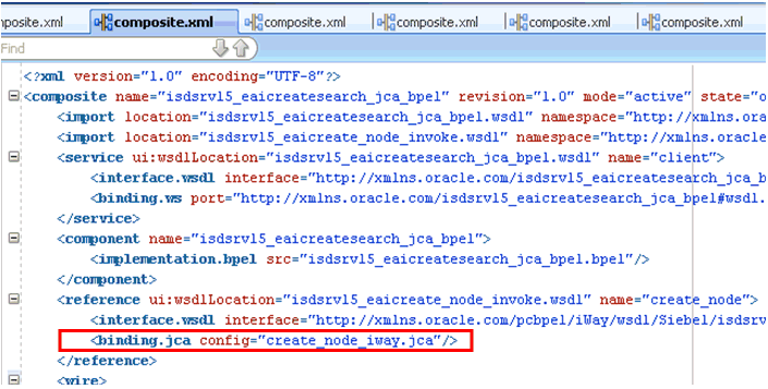
Description of "Figure 1-27 Source of the JCA Properties File"
-
Open the project folder and rename the same .jca properties file by adding _3P as a suffix in the .jca file (for example, create_node_iway_3P.jca).
Upgrading a 10.1.3.x Inbound Process to 11g
This section describes how to upgrade a 10.1.3.x inbound process to 11g.
Note:
For demonstration purposes, Oracle Application Adapter for SAP R/3 is used as an example.As a requirement, you must create the same adapter targets and channels in the 11g environment using Application Explorer that you had created in the 10.1.3.x environment. Any change in the adapter target or channel can cause issues for the projects to work in 11g environment.
Overview of 10.1.3.x BPEL JCA Inbound Workflow Process
-
Using Application Explorer, generate a 10.1.3.x JCA inbound WSDL document for Oracle Application Adapter for SAP R/3.
-
Create a 10.1.3.x BPEL JCA inbound process using Oracle JDeveloper 10.1.3.x and deploy it successfully.
-
Trigger the event messages from the ERP system (for example, SAP GUI) and verify that successful instances are received for the deployed process in the BPEL console.
-
Migrate the 10.1.3.x BPEL JCA inbound process to 11g using Oracle JDeveloper 11g.
-
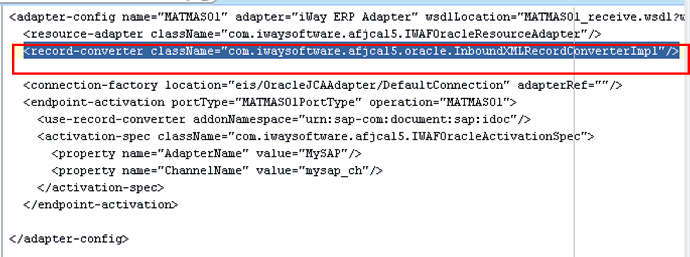
Remove the following line from the JCA properties file in the migrated project and deploy it successfully:
<record-converter className="com.iwaysoftware.afjca15.oracle.InboundXMLRecordConverterImpl"/>
-
Trigger the event messages from the ERP system (for example, SAP GUI) and ensure that successful instances are received in the Oracle Enterprise Manager console.
Creating an Inbound BPEL Process Project
To create an inbound BPEL process project:
-
As shown in Figure 1-28, start Oracle JDeveloper 10.1.3.4.
-
Click the Application Navigator tab and select New Project from the context menu.
The New Gallery dialog is displayed, as shown inFigure 1-29.
-
Select the BPEL Process Project and then click OK.
The BPEL Project Creation Wizard - Project Settings page is displayed, as shown in Figure 1-30.
Figure 1-30 BPEL Project Creation Wizard - Project Settings Page
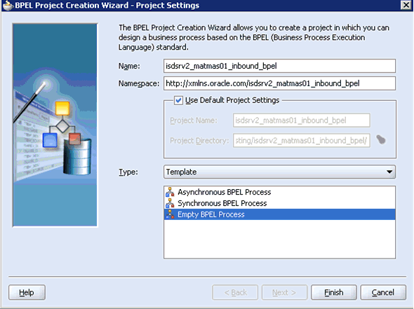
Description of "Figure 1-30 BPEL Project Creation Wizard - Project Settings Page"
-
Enter a name for the new BPEL process project in the Name field.
-
Select Empty BPEL Process from the Template Type list and click Finish. Figure 1-31 shows the BPEL inbound process.
Figure 1-31 A Standard BPEL Inbound Process
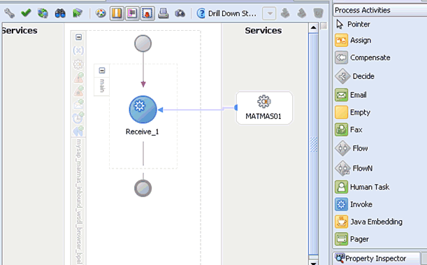
Description of "Figure 1-31 A Standard BPEL Inbound Process"
-
Continue with the creation of a standard BPEL inbound process using Partnerlink and Receive components.
-
Compile the inbound BPEL process project, as shown in Figure 1-32.
Figure 1-32 Messages Tab Showing Deployment Was Successful

Description of "Figure 1-32 Messages Tab Showing Deployment Was Successful"
-
Verify that there are no error or warning messages during compilation.
-
Deploy the inbound BPEL process project.
-
After the deployment is successful, trigger the event messages from the ERP system (for example, SAP GUI).
The successful instances for the deployed process are received in the BPEL console.
Migrating an Inbound BPEL Process Project
Before continuing, ensure that you copy and paste the 10.1.3.x inbound BPEL Process Project to the 11g system location.
To migrate an inbound BPEL process project:
-
As shown in Figure 1-33, start Oracle JDeveloper 11g.
Figure 1-33 Oracle JDeveloper 11g Open Icon
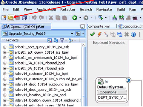
Description of "Figure 1-33 Oracle JDeveloper 11g Open Icon"
-
Select an available application and click Open from the tool bar.
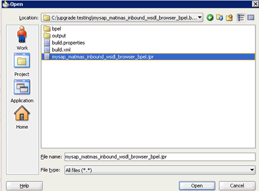
The Open dialog is displayed, as shown in Figure 1-34.
-
Open the 10.1.3.x project and select the .jpr extension file (for example, mysap_matmas_inbound_wsdl_browser_bpel.jpr).
-
Click Open.
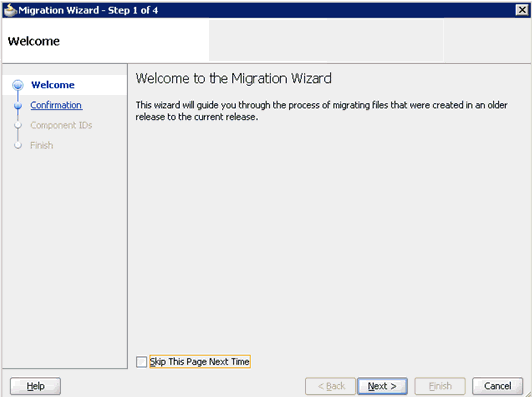
The Migration Wizard is displayed, as shown in Figure 1-35.
-
Click Next.
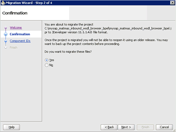
The Confirmation page is displayed, as shown in Figure 1-36.
-
Verify that Yes is selected (default) and click Next.
The Component IDs page is displayed, as shown in Figure 1-37.
-
Accept the default values and click Next.
The Finish page is displayed, as shown in Figure 1-38.
-
Click Finish.
The following message is displayed, as shown in Figure 1-39.
Figure 1-39 Migration Successfully Completed Message

Description of "Figure 1-39 Migration Successfully Completed Message"
-
Click OK.
As shown below in Figure 1-40, the 10.1.3.x project is now available in your 11g environment.
Figure 1-40 Migrated 10.1.3.x Project in the 11g Environment
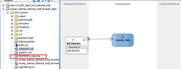
Description of "Figure 1-40 Migrated 10.1.3.x Project in the 11g Environment"
-
Expand the migrated project in the left page and double-click the composite.xml file to verify that the project opens without any errors.
-
Double-click the JCA properties file that is associated with this project (for example, MATMAS01_iway.jca).
-
Remove the
XMLRecordConverterline, as shown in Figure 1-41. -
Click Save.
-
Compile and then deploy the migrated BPEL process project, as shown in Figure 1-42.
Figure 1-42 Messages Tab - BPEL Process Object Compiled and Deployed Successfully

Description of "Figure 1-42 Messages Tab - BPEL Process Object Compiled and Deployed Successfully"
-
Verify that there are no error or warning messages during compilation and deployment.
-
After the deployment is successful, trigger the event messages from the ERP system (for example, SAP GUI).
The successful instances for the deployed process are received in the Oracle Enterprise Manager console.
Post-Upgrade Requirement
The following changes must be made for every inbound ESB and BPEL process after the corresponding project is migrated to 11g.
-
Expand the migrated project and double-click the composite.xml file.
-
Click source.
-
Navigate to the
servicesection, check for the .jca file that has the naming convention asxxxx_iway.jcaand replace withxxxx_iway_3P.jca(adding _3P as a suffix).Original:
<service ui:wsdlLocation="isdsrv22_sampleAcct_receive.wsdl" name="samp_node"><interface.wsdl interface="http://xmlns.oracle.com/pcbpel/iWay/wsdl/Siebel/isdsrv22/samp_node#wsdl.interface(samp_nodePortType)" xmlns:ns="http://xmlns.oracle.com/sca/1.0"/><binding.jca config="samp_node_iway.jca"/></service>Modified:
<service ui:wsdlLocation="isdsrv22_sampleAcct_receive.wsdl" name="samp_node"><interface.wsdl interface="http://xmlns.oracle.com/pcbpel/iWay/wsdl/Siebel/isdsrv22/samp_node#wsdl.interface(samp_nodePortType)" xmlns:ns="http://xmlns.oracle.com/sca/1.0"/><binding.jca config="samp_node_iway_3P.jca"/></service> -
Open the project folder and rename the same .jca properties file by adding _3P as a suffix in the .jca file (for example, samp_node_iway_3P.jca).
Migrating Oracle Service Bus 10.1.3.x/PS2 Outbound and Inbound Processes to 11g PS3
This section describes how to migrate outbound and inbound J2CA processes and outbound BSE processes from Oracle Service Bus 10.1.3.x/PS2 to 11g PS3. It contains the following topics:
-
Exporting the Configured Processes From Oracle Service Bus 10.1.3.x/PS2
-
Importing the Exported Processes to Oracle Service Bus 11g PS3
-
Additional Modifications for Imported Processes in Oracle Service Bus 11g PS3
Exporting the Configured Processes From Oracle Service Bus 10.1.3.x/PS2
This section describes how to export the configured processes from Oracle Service Bus 10.1.3.x/PS2.
-
Start the Oracle WebLogic Server for the Oracle WebLogic Server domain that you have configured.
-
Open the Oracle Service Bus console in a Web browser by entering the following URL:
http://host name:port/sbconsole
where
host nameis the name of the system where Oracle WebLogic Server is running (Oracle Service Bus 10.1.3.x/PS2) andportis the port for the domain you are using. The port for the default domain is 7001. -
Log in to the Oracle Service Bus console using a valid user name and password.
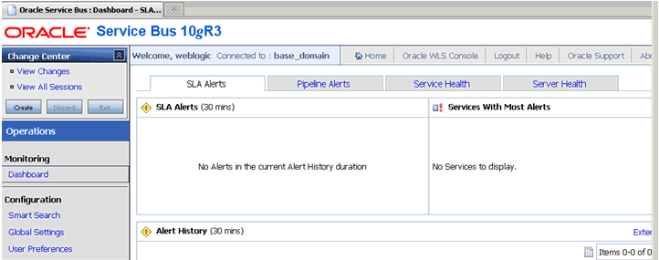
The Oracle Service Bus console home page is displayed, as shown in Figure 1-44.
Figure 1-44 Oracle Service Bus Console Home Page
Description of "Figure 1-44 Oracle Service Bus Console Home Page"
-
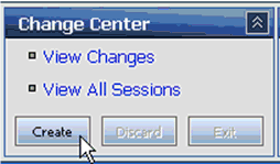
As shown in Figure 1-45, click Create in the Change Center area to start a new Oracle Service Bus session.
Figure 1-45 Create Button in Change Center Area
Description of "Figure 1-45 Create Button in Change Center Area"
-
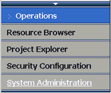
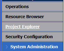
Click System Administration in the left pane, as shown in Figure 1-46.
-
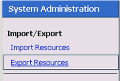
Click Export Resources in the Import/Export area, as shown in Figure 1-47.
-
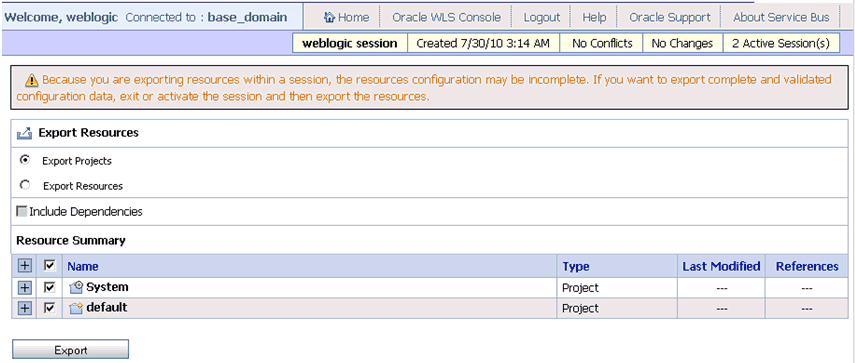
Ensure that all the available options under Resource Summary are selected (System and default), and then click Export, as shown in Figure 1-48.
Figure 1-48 Resource Summary Area and Export Button
Description of "Figure 1-48 Resource Summary Area and Export Button"
-
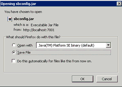
Save the
sbconfig.jarfile, as shown in Figure 1-49. -
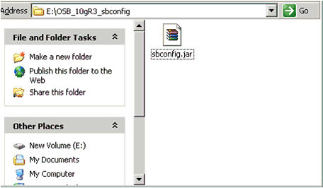
As shown in Figure 1-50, verify that the
sbconfig.jaris saved successfully.Figure 1-50 The sbconfig.jar File Saved Successfully in a File System Directory Location
Description of "Figure 1-50 The sbconfig.jar File Saved Successfully in a File System Directory Location"
Note:
Thesbconfig.jarfile that is exported from Oracle Service Bus 10.1.3.x/PS2 must be copied to the system where Oracle Service Bus 11g PS3 is installed.
Importing the Exported Processes to Oracle Service Bus 11g PS3
This section describes how to import the exported processes to Oracle Service Bus 11g PS3.
Prerequisites
-
All the adapter targets and channels that are configured using Application Explorer in an Oracle Service Bus 11g PS3 environment must match those in an Oracle Service Bus 10.1.3.x/PS2 environment.
-
All the input and output locations configured for the processes in an Oracle Service Bus 11g PS3 environment must match those in an Oracle Service Bus 10.1.3.x/PS2 environment.
To import the exported processes to Oracle Service Bus 11g PS3:
-
Start the Oracle WebLogic Server for the Oracle WebLogic Server domain that you have configured.
-
Open the Oracle Service Bus console in a Web browser by entering the following URL:
http://host name:port/sbconsole
where
host nameis the name of the system where Oracle WebLogic Server is running (Oracle Service Bus 11g PS3) andportis the port for the domain you are using. The port for the default domain is 7001. -
Log in to the Oracle Service Bus console using a valid user name and password.
The Oracle Service Bus console home page is displayed, as shown in Figure 1-51.
Figure 1-51 Oracle Service Bus Console Home Page
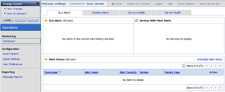
Description of "Figure 1-51 Oracle Service Bus Console Home Page"
-
Click Create in the Change Center area to start a new Oracle Service Bus session, as shown below in Figure 1-52.
Figure 1-52 Create Button in the Change Center Area

Description of "Figure 1-52 Create Button in the Change Center Area"
-
Click System Administration in the left pane, as shown in Figure 1-53.
-
As shown in Figure 1-54, click Import Resources in the Import/Export area.
Figure 1-54 Import Resources Option From Import/Export Area
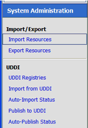
Description of "Figure 1-54 Import Resources Option From Import/Export Area"
The Import Resources page is displayed, as shown in Figure 1-55.
-
As shown in Figure 1-56, click Browse and select the
sbconfig.jarfile, which was exported from Oracle Service Bus 10.1.3.x/PS2 and copied to the local system.Figure 1-56 Browse Button on the Import Resources Page

Description of "Figure 1-56 Browse Button on the Import Resources Page"
-
Click Next.
-
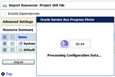
Select all the options listed in the Resource Summary area and click Import, as shown in Figure 1-57.
Figure 1-57 Import Button in the Resource Summary Area
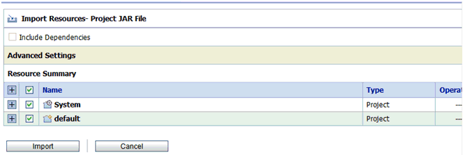
Description of "Figure 1-57 Import Button in the Resource Summary Area"
As shown below in Figure 1-58, the processes are imported.
-
Verify that the success message is displayed and click Activate, as shown in Figure 1-59.
Figure 1-59 Import Process Success Message and Activate Button
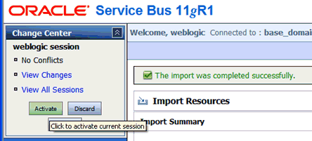
Description of "Figure 1-59 Import Process Success Message and Activate Button"
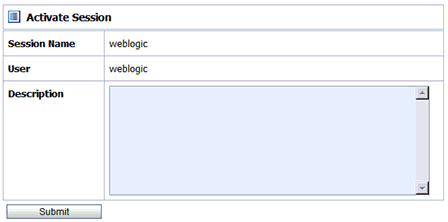
The Activate Session page is displayed, as shown in Figure 1-60.
-
Click Submit.
-
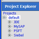
Click Project Explorer after the session is successfully activated, as shown in Figure 1-61.
-
As shown below in Figure 1-62, ensure that all the project folders are created.
The project folder structure must match the one from Oracle Service Bus 10.1.3.x/PS2, since you imported these settings from that environment.
-
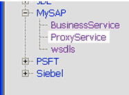
Expand an adapter folder, for example, mySAP, as shown in Figure 1-63.
Figure 1-63 Expanded mySAP Project Folder
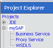
Description of "Figure 1-63 Expanded mySAP Project Folder"
-
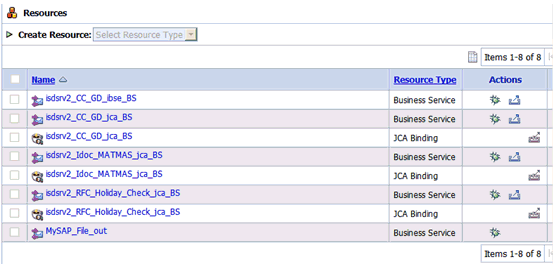
As shown in Figure 1-64, select the Business Service folder.
Ensure that all the Business Services that were created in the Oracle Service Bus 10.1.3.x/PS2 environment are included.
-
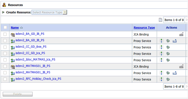
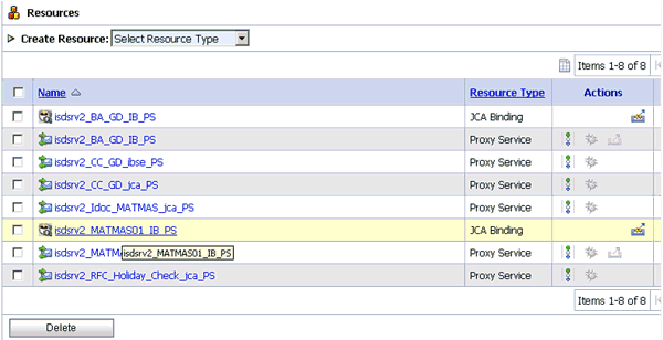
As shown in Figure 1-65, select the Proxy Service folder.
Ensure that all the Proxy Services that were created in the Oracle Service Bus 10.1.3.x/PS2 environment are included.
-
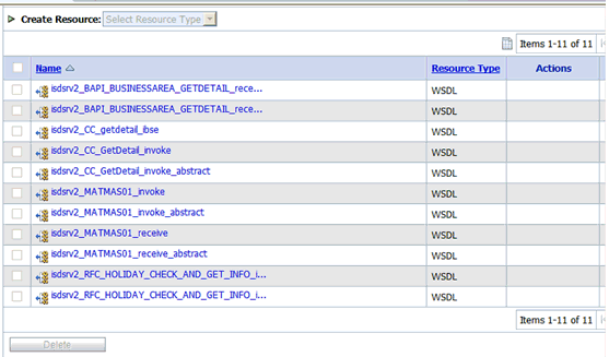
Select the WSDLS folder, as shown in Figure 1-66.
Ensure that all the WSDL files that were created in the Oracle Service Bus 10.1.3.x/PS2 environment are included.
Note:
For applications using Oracle Application Adapter for Siebel, the namespace declaration for the XML payload must use the version that is generated in Oracle Service Bus (OSB) 10g Release 3. The Oracle Application Adapter for Siebel namespace in OSB 10g Release 3 environments is different from Oracle Service Bus 11g PS3 environments.For example:
OSB 10g Release 3:
<sbl:Siebel location="S/BO/Account/Account/query" xmlns:sbl="urn:iwaysoftware:adapter:siebel:oct2004:request">OSB 11g:
<sbl:Siebel location="S/BO/Account/Account/query" xmlns:sbl="urn:iwaysoftware:adapter:siebel:request:S/BO/Account/Account/query">The change that is described in this note is only required if you are migrating an OSB 10g Release 3 process to 11g PS3. This change is not required if you are migrating an OSB 11g PS2 process to 11g PS3.
Additional Modifications for Imported Processes in Oracle Service Bus 11g PS3
This section describes additional modifications that are required for the imported processes in Oracle Service Bus 11g PS3.
Note:
Imported J2CA outbound processes in Oracle Service Bus 11g PS3 work properly and do not require any additional changes. Only BSE outbound processes and J2CA inbound processes require additional changes.This section contains the following topics:
Imported J2CA Inbound Processes
This section describes additional modifications that are required for imported J2CA inbound processes in Oracle Service Bus 11g PS3.
Note:
The changes that are described in this section are only required if you are migrating an OSB 10g Release 3 process to 11g PS3. If you are migrating an OSB 11g PS2 process to 11g PS3, then you can skip this section (1.3.3.1, "Imported J2CA Inbound Processes").-
Select the folder that contains the Proxy Services for your adapter in the Project Explorer, as shown in Figure 1-67.
-
Select the appropriate JCA binding file for the inbound process that must be changed, as shown in Figure 1-68.
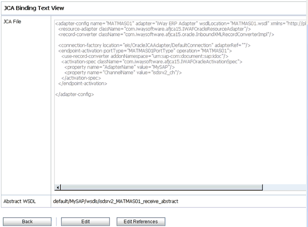
The JCA Binding Text View is displayed, as shown in Figure 1-69.
-
Click Edit.
-
Remove the
<record-converter>element, as shown in Figure 1-70.Figure 1-70 The <record-converter> Element

Description of "Figure 1-70 The <record-converter> Element"
-
As shown in Figure 1-71, click Save.
Imported BSE Outbound Processes
This section describes additional modifications that are required for imported BSE outbound processes in Oracle Service Bus 11g PS3.
-
Select the folder that contains the WSDL files for your adapter in the Project Explorer.
-
Select the specific WSDL file for the outbound process that must be changed, as shown in Figure 1-72.
Figure 1-72 WSDL File Selected for the Outbound Process
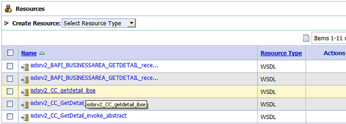
Description of "Figure 1-72 WSDL File Selected for the Outbound Process"
-
Click the Text View tab, as shown in Figure 1-73.
-
Click Edit.
The Edit a WSDL Resource page is displayed, as shown in Figure 1-74.
Figure 1-74 The Edit a WSDL Resource Page
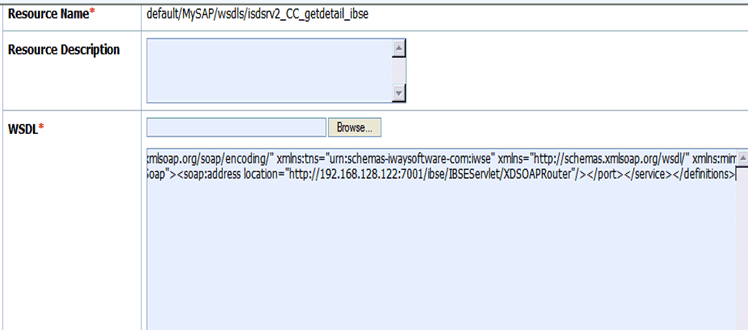
Description of "Figure 1-74 The Edit a WSDL Resource Page"
-
Change the
<soap:address location>element to point to the system where OSB 11g PS3 is running. For example:<soap:address location="http://OSB10gR3Machine:7001/ibse/IBSEServlet/XDSOAPRouter"/>must be changed to:
<soap:address location="http://OSB11gMachine:7001/ibse/IBSEServlet/XDSOAPRouter"/ -
Click Save.
-
Select a Business Service that is created for a BSE outbound process in the Project Explorer.
-
Click Edit in the Configuration details tab.
-
In the Transport Configuration section, update the value for the Endpoint URI property to point to the system where OSB 11g PS3 is running, as shown in Figure 1-75.
Figure 1-75 Transport Configuration Section
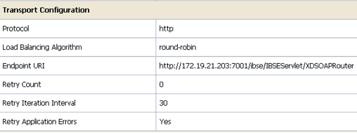
Description of "Figure 1-75 Transport Configuration Section"
For example:
<soap:address location="http://OSB10gR3Machine:7001/ibse/IBSEServlet/XDSOAPRouter"/>must be changed to:
<soap:address location="http://OSB11gMachine:7001/ibse/IBSEServlet/XDSOAPRouter"/Note:
The best option for both changes would be to uselocalhostinstead of an IP address, which eliminates the need for this change.
Upgrading 11g PS1/PS2 Outbound and Inbound BPEL and Mediator Processes to 11g PS3
As a prerequisite, ensure that the adapter targets and channels created using Application Explorer for J2CA configurations in the Oracle 11g PS3 environment are identical to those created in the Oracle 11g PS1/PS2 environment. For BSE configurations, ensure that the adapter targets and Business Services created using Application Explorer in the Oracle 11g PS3 environment are identical to those created in the Oracle 11g PS1/PS2 environment.
In addition, ensure that you copy the Oracle 11g PS1/PS2 BPEL and Mediator processes for BSE and J2CA to the Oracle 11g PS3 upgraded system location.
-
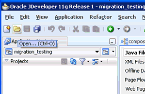
Open Oracle JDeveloper 11g Release 1 (11.1.1.4.0).
-
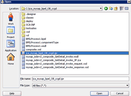
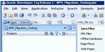
Select an available application (for example, migration-testing) and click Open from the toolbar, as shown in Figure 1-76.
The Open dialog is displayed, as shown in Figure 1-77.
-
Open the 11g PS1/PS2 project (for example, jca_mysap_bpel_OB ccgd) and then select the .jpr extension file (for example, jca_mysap_bpel_OB ccgd.jpr).
-
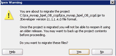
Click Open.
The Open Warning dialog is displayed, as shown in Figure 1-78.
-
Click Yes.
The Migration Status message is displayed, as shown in Figure 1-79.
-
Click OK.
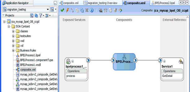
The Oracle 11g PS1/PS2 project is now available in your Oracle 11g PS3 environment, as shown in Figure 1-80.
-
Expand the migrated project in the left pane (for example, jca mysap_bpel_OB_ccgd) and then double-click the composite.xml file to verify that the project opens without any errors.
-
Click Save.
-
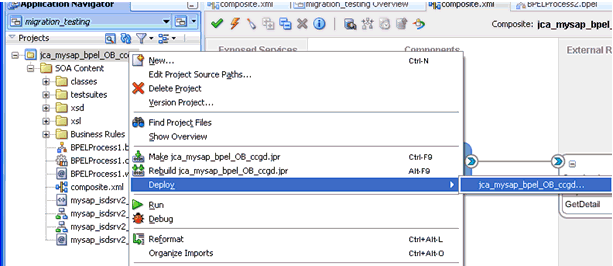
Right-click the migrated project, click Deploy, and select the project name from the menu (for example, jca_mysap bpel_OB_ccgd), as shown in Figure 1-81.
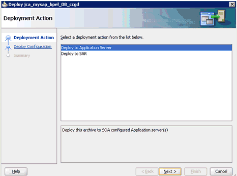
The Deployment Action page is displayed, as shown in Figure 1-82.
-
Ensure that Deploy to Application Server is selected.
-
Click Next.
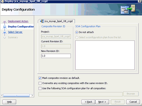
The Deploy Configuration page is displayed, as shown in Figure 1-83.
-
Leave the default values selected and click Next.
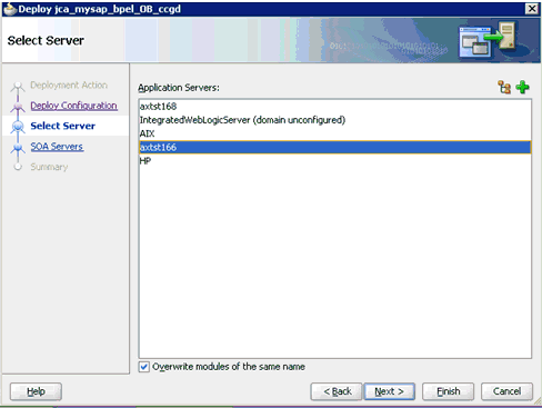
The Select Server page is displayed, as shown in Figure 1-84.
-
Select the configured server and click Next.
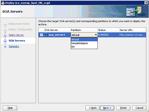
The SOA Servers page is displayed, as shown in Figure 1-85.
-
Select a partition from the Partition column list and click Next.
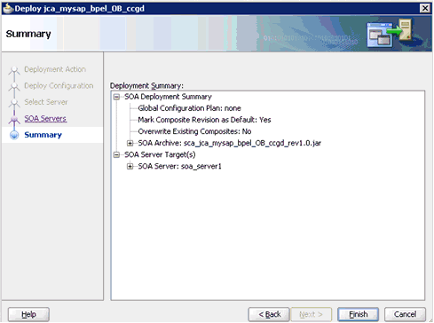
The Summary page is displayed, as shown in Figure 1-86.
-
Review and verify all the available deployment information for your project and click Finish.
-
Verify that there are no error or warning messages during compilation and deployment in the deployment log, as shown in Figure 1-87.
-
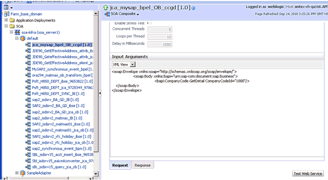
After the deployment is successful, open the Oracle Enterprise Manager console and execute the deployed process either in Tree View or XML View to receive a successful response, as shown in Figure 1-88 and Figure 1-89.
Workaround for PS1 J.D. Edwards OneWorld Outbound Mediator Process When Migrating to 11g PS2/PS3
Once the J.D. Edwards OneWorld Mediator process is copied into 11g PS2/PS3 system, perform the following steps:
-
Open the PS1 project folder and open the WSDL file generated from Application Explorer to edit and perform the following changes:
Original
<definitionsname="GetPhone"targetNamespace="http://xmlns.oracle.com/pcbpel/iWay/wsdl/JDEdwards/jde_90_attr_tgt/GetPhone"xmlns="http://schemas.xmlsoap.org/wsdl/"xmlns:iWayRequest="urn:iwaysoftware:jde/services/CALLBSFN/Addressbook/GetPhone"xmlns:GetPhone="http://xmlns.oracle.com/pcbpel/iWay/wsdl/JDEdwards/jde_90_attr_tgt/GetPhone"xmlns:plt="http://schemas.xmlsoap.org/ws/2003/05/partner-link/">..............<schema xmlns="http://www.w3.org/2001/XMLSchema"><import schemaLocation="jde90_GetPhone_invoke_response.xsd" namespace="urn:iwaysoftware:jde/services/CALLBSFN/Addressbook/GetPhone"/></schema>................<message name="response"><part name="output_GetPhone" element="iWayRequest:jdeResponse"/></message>
Modified
<definitionsname="GetPhone"targetNamespace="http://xmlns.oracle.com/pcbpel/iWay/wsdl/JDEdwards/jde_90_attr_tgt/GetPhone"xmlns="http://schemas.xmlsoap.org/wsdl/"xmlns:iWayResponse="urn:iwaysoftware:jde/services/CALLBSFN/Addressbook/GetPhone.response"xmlns:iWayRequest="urn:iwaysoftware:jde/services/CALLBSFN/Addressbook/GetPhone"xmlns:GetPhone="http://xmlns.oracle.com/pcbpel/iWay/wsdl/JDEdwards/jde_90_attr_tgt/GetPhone"xmlns:plt="http://schemas.xmlsoap.org/ws/2003/05/partner-link/">..............................<schema xmlns="http://www.w3.org/2001/XMLSchema"><import schemaLocation="jde90_GetPhone_invoke_response.xsd" namespace="urn:iwaysoftware:jde/services/CALLBSFN/Addressbook/GetPhone.response"/></schema>..................................<message name="response"><part name="output_GetPhone" element="iWayResponse:jdeResponse"/></message>
-
Open the
response.xsdfile generated from Application Explorer to edit and.responseto the end of thetargetNamespaceandnsdeclaration. For example:Original
<xsd:schema xmlns:xsd=http://www.w3.org/2001/XMLSchema targetNamespace="urn:iwaysoftware:jde/services/CALLBSFN/Addressbook/GetPhone"xmlns:ns="urn:iwaysoftware:jde/services/CALLBSFN/Addressbook/GetPhone" elementFormDefault="qualified">
Modified
<xsd:schema xmlns:xsd="http://www.w3.org/2001/XMLSchema" targetNamespace="urn:iwaysoftware:jde/services/CALLBSFN/Addressbook/GetPhone.response"xmlns:ns="urn:iwaysoftware:jde/services/CALLBSFN/Addressbook/GetPhone.response" elementFormDefault="qualified">
-
Open the
MediatorComponentName.wsdlfile (for example,Mediator.wsdl) to edit and perform the following changes:Original
<wsdl:definitions name="Mediator1"targetNamespace="http://xmlns.oracle.com/ps1_project/ps1_jca_jd90_medi_gephone/Mediator1" xmlns:wsdl=http://schemas.xmlsoap.org/wsdl/xmlns:inp1="urn:iwaysoftware:jde/services/CALLBSFN/Addressbook/GetPhone"xmlns:tns=http://xmlns.oracle.com/ps1_project/ps1_jca_jd90_medi_gephone/Mediator1xmlns:out1="urn:iwaysoftware:jde/services/CALLBSFN/Addressbook/GetPhone"><wsdl:import namespace="urn:iwaysoftware:jde/services/CALLBSFN/Addressbook/GetPhone" location="jde90_GetPhone_invoke.wsdl"/><wsdl:import namespace="urn:iwaysoftware:jde/services/CALLBSFN/Addressbook/GetPhone" location="jde90_GetPhone_invoke.wsdl"/> ………………………………………….. <wsdl:message name="replyMessage"> <wsdl:part name="reply" element="inp1:jdeResponse"/> </wsdl:message>
Modified
<wsdl:definitions name="Mediator1"targetNamespace="http://xmlns.oracle.com/ps1_project/ps1_jca_jd90_medi_gephone/Mediator1" xmlns:wsdl="http://schemas.xmlsoap.org/wsdl/" xmlns:inp1="urn:iwaysoftware:jde/services/CALLBSFN/Addressbook/GetPhone"xmlns:tns="http://xmlns.oracle.com/ps1_project/ps1_jca_jd90_medi_gephone/Mediator1"xmlns:out1="urn:iwaysoftware:jde/services/CALLBSFN/Addressbook/GetPhone.response"><wsdl:import namespace="urn:iwaysoftware:jde/services/CALLBSFN/Addressbook/GetPhone" location="jde90_GetPhone_invoke.wsdl"/><wsdl:import namespace="urn:iwaysoftware:jde/services/CALLBSFN/Addressbook/GetPhone.response" location="jde90_GetPhone_invoke.wsdl"/> ……………………………….. <wsdl:message name="replyMessage"> <wsdl:part name="reply" element="out1:jdeResponse"/></wsdl:message>
-
Start Oracle JDeveloper 11g and migrate the PS1 Mediator project.
-
Once the project is migrated, a successful message is received in Oracle JDeveloper.
-
Expand the migrated project and double-click the composite.xml file to ensure that the project opens without any errors.
Since changes were made to the WSDL file for the response section, a new mapper file must be created for
jdeResponse. -
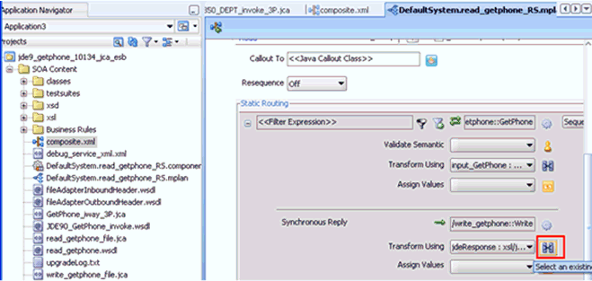
Double-click the mediator component and go to the Synchronous Reply area.
-
Click the Select an existing mapper file or create a new one button in the Transform Using field, as shown in Figure 1-90.
The Reply Transformation Map dialog is displayed, as shown in Figure 1-91.
Figure 1-91 Reply Transformation Map Dialog

Description of "Figure 1-91 Reply Transformation Map Dialog"
-
Click the Create New Mapper File option and click OK.
-
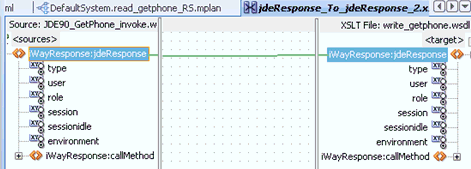
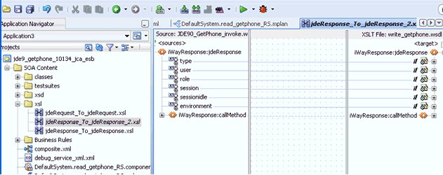
Automap the iWayResponse:jdeResponse in the source and iWayResponse:jdeResponse in the target, as shown in Figure 1-92.
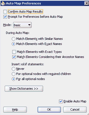
The Auto Map Preferences dialog is displayed, as shown in Figure 1-93.
-
Accept the default values and click OK.
The automap is completed successfully, as shown in Figure 1-94.
-
Double click the composite.xml file.
-
Save and then deploy the migrated Mediator project.
-
Ensure that there are no error or warning messages during the deployment process.
-
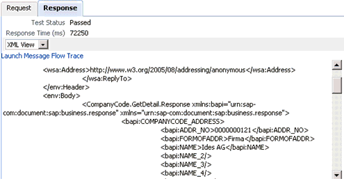
Once the deployment is successful, navigate to the Oracle Enterprise Manager console and invoke the input XML file for the particular deployed project in the Request tab.
The successful response XML is received in the Response tab.
Additional Modifications for Migrated Processes in 11g PS3
Upgraded J2CA outbound and inbound processes in 11g PS3 function properly and do not require any additional modifications. Only BSE outbound processes require additional modifications, which are described in this section.
-
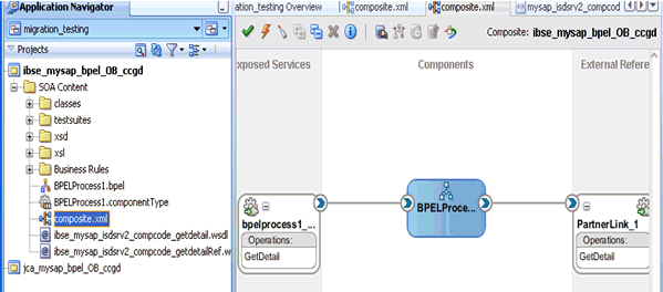
Once the BSE outbound process is migrated successfully to 11g PS3, double-click the composite.xml file to open the migrated project, as shown in Figure 1-95
-
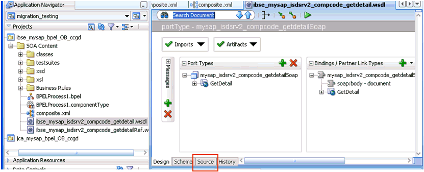
Double-click the BSE outbound WSDL file and then click the Source tab, as shown in Figure 1-96
-
Change the
<soap:address location>element to point to the system where 11g PS3 is running.For example:
<service name="mysap_isdsrv2_compcode_getdetail"> <documentation/><port name="mysap_isdsrv2_compcode_getdetailSoap1" binding="tns:mysap_isdsrv2_compcode_getdetailSoap"><soap:address location="http://172.19.95.190:8001/ibse/IBSEServlet/XDSOAPRouter"/> </port> </service></definitions>
Note:
The best option for both changes is to use localhost instead of an IP address, which eliminates the need for this change. -
Save and deploy the process.
Upgrading 11g PS2 Outbound and Inbound BPM Processes to 11g PS3
As a prerequisite, ensure that the adapter targets and channels created using Application Explorer for J2CA configurations in the Oracle 11g PS3 environment are identical to those created in the Oracle 11g PS2 environment. For BSE configurations, ensure that the adapter targets and Business Services created using Application Explorer in the Oracle 11g PS3 environment are identical to those created in the Oracle 11g PS2 environment.
In addition, ensure that you copy the Oracle 11g PS2 BPM processes for BSE and J2CA to the Oracle 11g PS3 upgraded system location.
-
Open Oracle JDeveloper 11g Release 1 (11.1.1.4.0).
-
Select an available application (for example, BPM_Migration_Testing) and click Open from the toolbar, as shown in Figure 1-97.
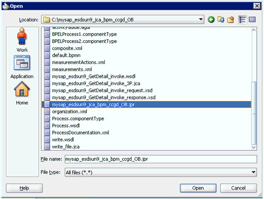
The Open dialog is displayed, as shown in Figure 1-98.
-
Open the 11g PS2 project (for example, mysap_esdsun9_jca_bpm_ccgd_OB) and then select the .jpr extension file (for example, mysap_esdsun9_jca_bpm_ccgd_OB.jpr).
-
Click Open.
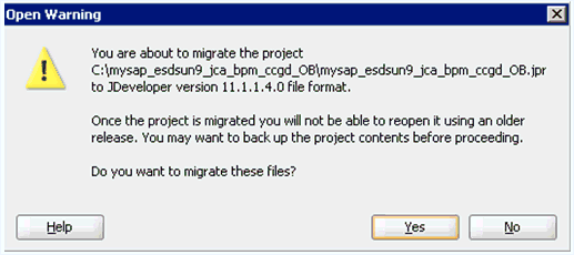
The Open Warning dialog is displayed, as shown in Figure 1-99.
-
Click Yes.
The Migration Status message is displayed, as shown in Figure 1-100.
-
Click OK.
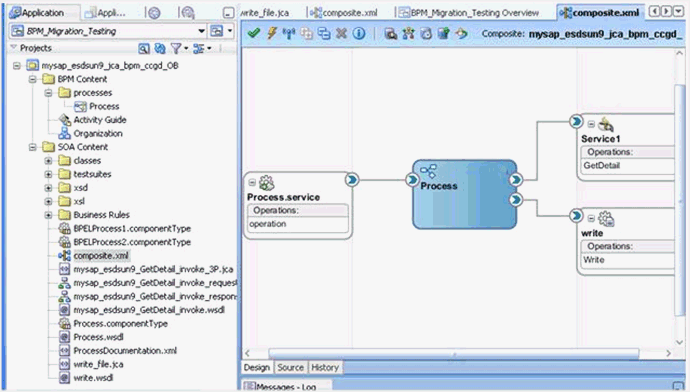
The Oracle 11g PS2 project is now available in your Oracle 11g PS3 environment, as shown in Figure 1-101.
-
Expand the migrated project in the left pane (for example, mysap_esdsun9_jca_bpm_ccgd_OB) and then double-click the composite.xml file to verify that the project opens without any errors.
-
Click Save.
-
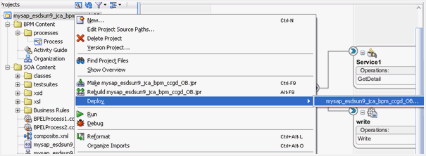
Right-click the migrated project, click Deploy, and select the project name from the menu (for example, mysap_esdsun9_jca_bpm_ccgd_OB), as shown in Figure 1-102.
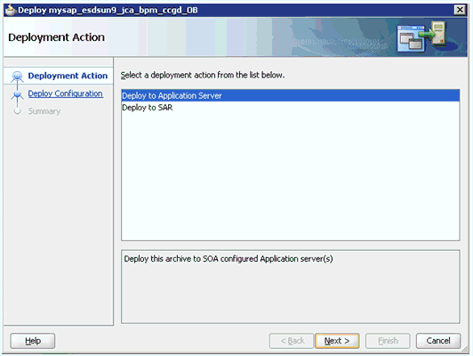
The Deployment Action page is displayed, as shown in Figure 1-103.
-
Ensure that Deploy to Application Server is selected.
-
Click Next.
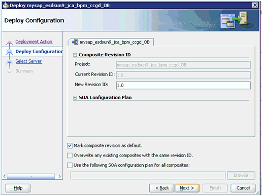
The Deploy Configuration page is displayed, as shown in Figure 1-104.
-
Leave the default values selected and click Next.
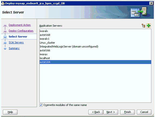
The Select Server page is displayed, as shown in Figure 1-105.
-
Select the configured server and click Next.
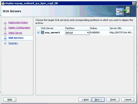
The SOA Servers page is displayed, as shown in Figure 1-106.
-
Select a partition from the Partition column list and click Next.
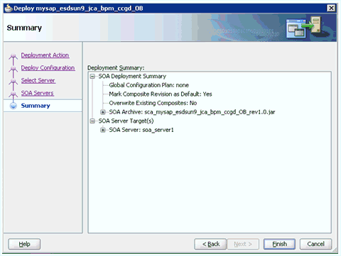
The Summary page is displayed, as shown in Figure 1-107.
-
Review and verify all the available deployment information for your project and click Finish.
-
Verify that there are no error or warning messages during compilation and deployment in the deployment log, as shown in Figure 1-108.
-
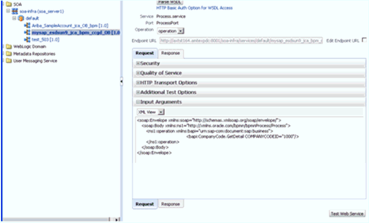
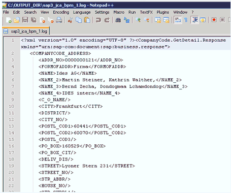
After the deployment is successful, open the Oracle Enterprise Manager console and execute the deployed process either in Tree View or XML View to receive a successful response, as shown in Figure 1-109 and Figure 1-110.
Workaround for J2CA BPM Processes
This section describes a workaround for J2CA BPM processes when migrating BAPI or RFC objects for MySAP adapter from 11g PS2 to 11g PS3.
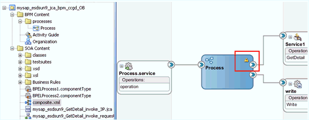
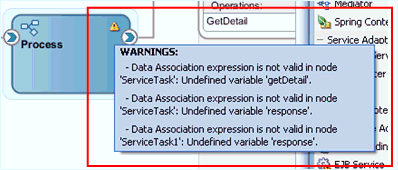
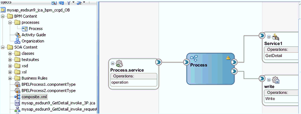
When a 11g PS2 J2CA BPM outbound process for the CompanyCode GetDetail object is migrated, a warning symbol is displayed in the 11g PS3 version of Oracle JDeveloper, as shown in Figure 1-111.
When you move your pointer over the warning symbol, warning messages are displayed, as shown in Figure 1-112.
For example:
WARNINGS:-Data Association expression is not valid in node 'ServiceTask': Undefined variable 'getDetail'.- Data Association expression is not valid in node 'ServiceTask': Undefined variable 'response'.- Data Association expression is not valid in node 'ServiceTask1': Undefined variable 'response'.
This section provides instructions on how to apply a workaround that resolves this issue.
Note:
This workaround is applicable to Oracle BUG 11798374 - migration ps2-> ps3 bug.-
Open the composite.xml file from the project folder and double-click the BPM Process component.
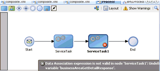
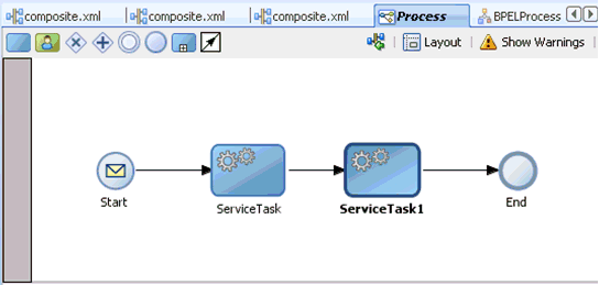
The BPM process is opened and you are able to see the ServiceTask and ServiceTask1 activities, including the error symbols, as shown in Figure 1-113.
-
Double-click the ServiceTask activity.
The Properties - ServiceTask dialog is displayed, as shown in Figure 1-114.
Figure 1-114 Properties - ServiceTask Dialog
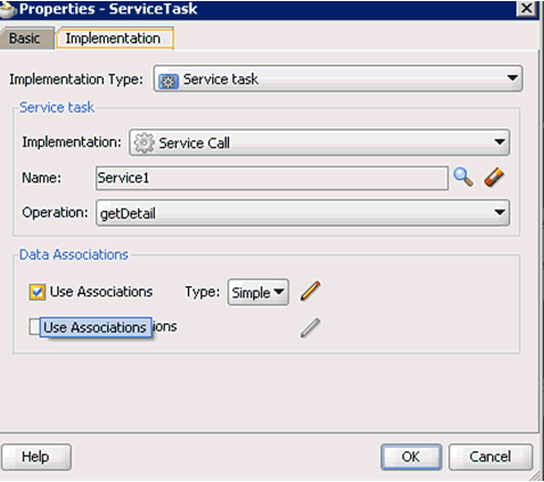
Description of "Figure 1-114 Properties - ServiceTask Dialog"
-
Click the Implementation tab.
-
Uncheck the Use Associations option.
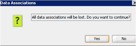
A confirmation message is displayed in the Data Associations dialog, as shown in Figure 1-115.
-
Click Yes.
You are returned to the Properties - ServiceTask dialog, as shown in Figure 1-116.
Figure 1-116 Properties - ServiceTask Dialog
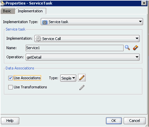
Description of "Figure 1-116 Properties - ServiceTask Dialog"
-
Select the Use Associations option and then click the Edit Data Associations icon.
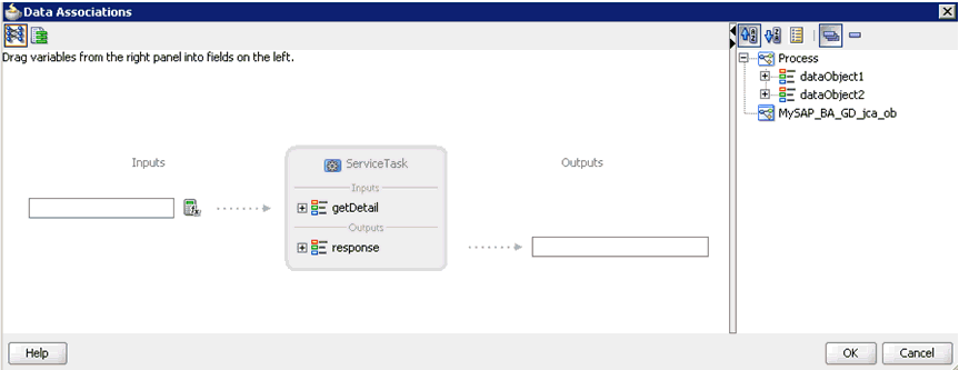
The Data Associations window is displayed, as shown in Figure 1-117.
-
Drag and drop dataobject1 (request) to the Inputs field and dataobject2 (response) to the Outputs field, as shown in Figure 1-118.
Figure 1-118 Dataobject1 and Dataobject 2
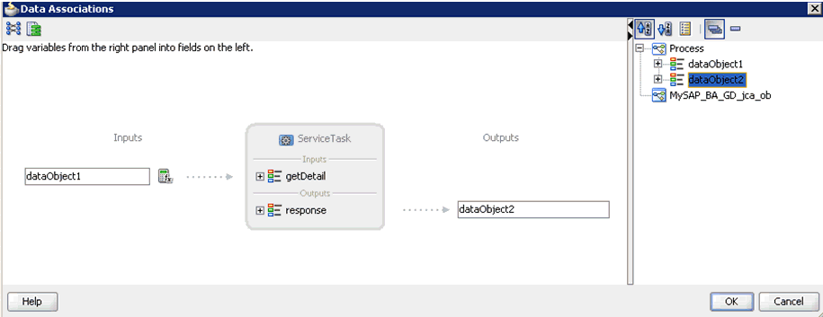
Description of "Figure 1-118 Dataobject1 and Dataobject 2"
-
Click OK.
You are returned to the Properties - ServiceTask dialog, as shown in Figure 1-119.
Figure 1-119 Properties - ServiceTask Dialog
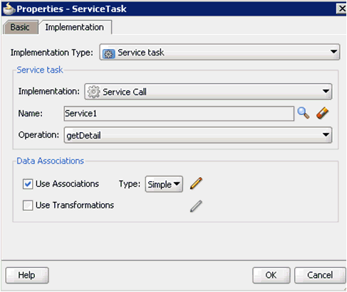
Description of "Figure 1-119 Properties - ServiceTask Dialog"
-
Click OK.
You are returned to the Process tab, as shown in Figure 1-120.
-
Double-click the ServiceTask1 activity.
The Properties - ServiceTask1 dialog is displayed, as shown in Figure 1-121.
Figure 1-121 Properties - ServiceTask1 Dialog
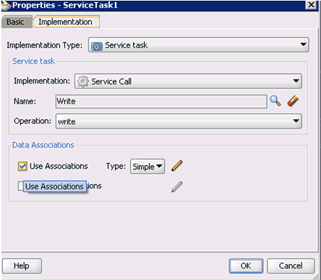
Description of "Figure 1-121 Properties - ServiceTask1 Dialog"
-
Click the Implementation tab.
-
Uncheck the Use Associations option.
A confirmation message is displayed in the Data Associations dialog, as shown in Figure 1-122.
-
Click Yes.
You are returned to the Properties - ServiceTask1 dialog, as shown in Figure 1-123.
Figure 1-123 Properties - ServiceTask1 Dialog
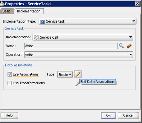
Description of "Figure 1-123 Properties - ServiceTask1 Dialog"
-
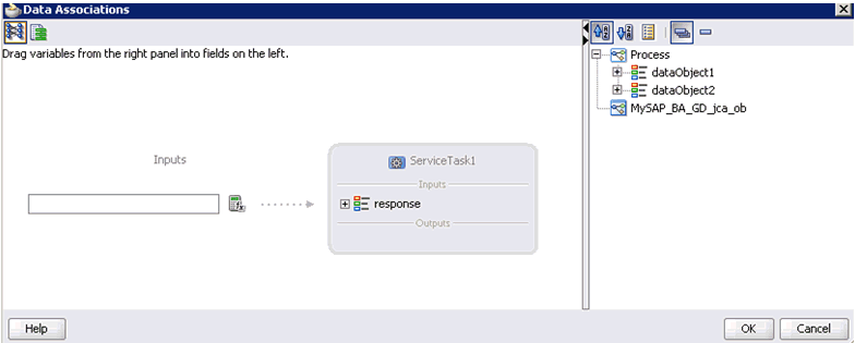
Select the Use Associations option and then click the Edit Data Associations icon.
The Data Associations window is displayed, as shown in Figure 1-124.
-
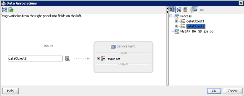
Drag and drop dataobject2 (response) to the Inputs field, as shown in Figure 1-125.
-
Click OK.
You are returned to the Properties - ServiceTask1 dialog, as shown in Figure 1-126.
Figure 1-126 Properties - ServiceTask1 Dialog
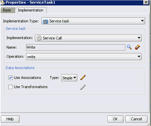
Description of "Figure 1-126 Properties - ServiceTask1 Dialog"
-
Click OK.
You are returned to the Process tab, as shown in Figure 1-127.
Notice that no errors or warnings are being indicated.
-
Save the process.
-
Double-click the composite.xml file.
Notice that the warning symbol is still indicated in the BPM Process component, as shown in Figure 1-128.
-
Restart Oracle JDeveloper.
Once Oracle JDeveloper has restarted, the warning symbol is not indicated in the BPM Process component, as shown in Figure 1-129.
Additional Modifications for Migrated Processes in 11g PS3
Upgraded J2CA outbound and inbound processes in 11g PS3 function properly and do not require any additional modifications. Only BSE outbound processes require additional modifications, which are described in this section.
-
Once the BSE outbound process is migrated successfully to 11g PS3, double-click the composite.xml file to open the migrated project, as shown in Figure 1-130
-
Double-click the BSE outbound WSDL file and then click the Source tab, as shown in Figure 1-131
-
Change the
<soap:address location>element to point to the system where 11g PS3 is running.For example:
<service name="mysap_isdsrv2_compcode_getdetail"> <documentation/><port name="mysap_isdsrv2_compcode_getdetailSoap1" binding="tns:mysap_isdsrv2_compcode_getdetailSoap"><soap:address location="http://172.19.95.190:8001/ibse/IBSEServlet/XDSOAPRouter"/> </port> </service></definitions>
Note:
The best option for both changes is to use localhost instead of an IP address, which eliminates the need for this change. -
Save and deploy the process.
