This chapter describes the Topology view. Topology is only available on the navigation bar if a replication topology, InnoDB Cluster, or NDB Cluster is selected.
The Topology tab graphically displays the replication topology of the selected group.
The Topology view contains the following:
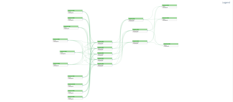
Topology graph: graphically displays the replication setup, enabling you to reposition the nodes for better visibility, and zoom in and out using your mouse wheel.
Tooltips: For information on an individual node or channel, hover the mouse cursor over the node or channel. A tooltip is displayed containing information about the node or channel. The node tooltip displays the ID, Name, and Status of the node, while the channel tooltip displays the name of the channel.
Legend : displays the meaning of each of the graphical elements.
Nodes:
Node OK
Replication Issues
Node/Replication Down
Node Unmonitored
Links:
Async Fetch OK
Async Fetch Down
Semi-Sync Fetch OK
Semi-Sync Fetch Down
Group Replication Recovery
Link Status Unknown
Group replication Status:
Online
Group Replication Recovering
Offline/Error
Unknown/Plugin Not Available
The topology graph displays semi-synchronous links only if both source and replica use the semi-sync plugins.
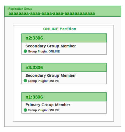
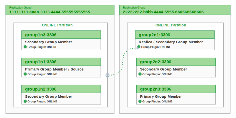
Group replication topologies are displayed differently. For example, the following is a three-node group:
While the following shows normal communication between two groups:
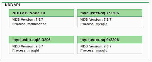
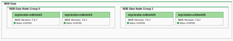
NDB Cluster topologies contain all the cluster components, Management node, API node, and data node, and uses color to display their states. Each layer is identified by host or process information. Further information can be seen by hovering the cursor over any of the elements.
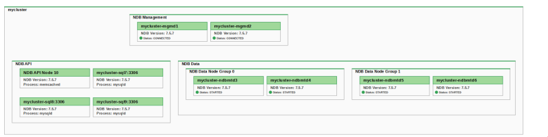
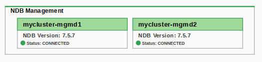
NDB Management Node:
NDB API Node: