Testing the Telephony Adapter
This chapter covers the following topics:
- Starting and Stopping the Test Utility
- Using Log Windows
- Oracle Telephony Adapter Server
- Configuring the Oracle Telephony Adapter Server Log
- Configuring Middleware
- Starting and Stopping Oracle Telephony Adapter Server
- Verification Tool
- Configuring the Verification Process
- Configuring Agent Information
- Starting and Stopping the Verification Tool
- TeleDevice Test Utility
- TeleDevices
- Assigning TeleDevices
- Connecting and Disconnecting a TeleDevice
- Deassigning a TeleDevice
- Viewing Events
- Invoking API Methods
- Disconnecting a TeleDevice
- Launching the Softphone
- Closing the Softphone
- Switch Simulator
- Starting and Stopping the Switch Simulator
- Configuring Switch Simulator Server Settings
- Configuring Simulated Extensions and Route Points
- Configuring the Switch Simulator for Standard or Advanced Integration
- Configuring the Switch Simulator for Basic Integration
- Javadoc
Starting and Stopping the Test Utility
The Oracle Telephony SDK Integrated Test Utility is a tool for testing the Telephony Adapter implementation, which is loaded and run by the Oracle Telephony Adapter Server. The Telephony SDK Integrated Test Utility contains user interfaces for running the Oracle Telephony Adapter Server, the Verification Tool, the TeleDevice Test Utility, Switch Simulator, and the Javadoc. Developers can use the Oracle Telephony SDK Integrated Test Utility to test the full functions of the TeleDevice implementations.
The Oracle Telephony SDK Integrated Test Utility interface has five tabs:
-
Oracle Telephony Adapter Server, for configuring and running the Oracle Telephony Adapter Server
-
Verification Tool, for configuring and running the TeleDevices
-
TeleDevice Test Utility, for configuring and running the TeleDevice and softphone
-
Switch Simulator, for configuring and running the switch simulator
-
Help, which displays the Javadoc
Use the following procedures to start and stop the Oracle Telephony SDK Integrated Test Utility.
Log in
Not applicable
Responsibility
Not applicable
Prerequisites
-
Obtain the Oracle Telephony SDK Zip file.
-
Update the SDK_JRE_HOME environment variable in the file sdkenv.cmd to point to a JDK installation, such as D:/jdk1.2.2.
Steps
-
Navigate to the directory oracle/apps/cct/bin.
-
The Oracle Telephony Adapter SDK Integrated Test Utility appears, opened to the Oracle Telephony Adapter Server tab > Server sub tab.
-
To stop the Oracle Telephony SDK Integrated Test Utility, close the Oracle Telephony Adapter SDK Integrated Test Utility window.
Using Log Windows
By default each main tab (excluding Help) of the Oracle SDK Integrated Test Utility includes a Log window that shows the progress and completion of configurations. To view the log messages in a separate, individual window, right click in the Log window and select Undock. The Log window detaches as a smaller, separate window that contains the log messages.
To close the separate log window and restore the log file to the main Log window, right click in the separate window and select Dock.
To clear log messages, right click in the selected log window and select Clear.
Oracle Telephony Adapter Server
The Oracle Telephony SDK Integrated Test Utility's Oracle Telephony Adapter Server user interface consists of the Server tab, to stop Oracle Telephony Adapter Server and to configure and view logs, and the Middleware tab, and configure CTI middleware.
Note: Oracle Telephony Adapter Server cannot be started in the Middleware tab.
Configuring the Oracle Telephony Adapter Server Log
Use the following procedure to configure the Oracle Telephony Adapter Server log.
Log in
Not applicable
Responsibility
Not applicable
Prerequisite
Install and configure Oracle Telephony Adapter SDK.
Steps
-
Select the Oracle Telephony Adapter Server tab > Server sub tab.
-
From the Log Level list, select one of the four log levels:
-
error, to print only error messages
-
warning, to print error and warning messages
-
info, to print error, warning and information messages
-
verbose, to print all messages
-
-
In the Log Directory field, enter the directory path of the log file. The log file created by Oracle Telephony Adapter Server is named using the pattern OTASyyyymmdd_hhmmss.log. The default directory is oracle/apps/cct/bin/log.
-
Select File > Save to save the configuration.
Configuring Middleware
In the Oracle Telephony SDK Integrated Test Utility, the Oracle Telephony Adapter Server middleware configuration consists of three types of data:
-
Data that Oracle Telephony Adapter Server requires to load the correct type of adapter, which includes the Middleware Type, Library Name and Factory Class Name.
-
Custom data that the adapter requires to be connected to the third-party CTI middleware systems, which includes IP addresses, ports and custom attributes. This data is passed to the TeleDeviceFactory.init() method.
-
Dialing data in the Dialing section that Oracle Telephony Manager requires to generate the local dial string based on the location from which the call is placed. Typically, developers are not required to use the data in the Dialing section.
Use the following procedure to configure middleware.
Log in
Not applicable
Responsibility
Not applicable
Prerequisite
Install and configure Oracle Telephony Adapter SDK.
Steps
-
In the Oracle Telephony SDK Integrated Test Utility, select the Oracle Telephony Adapter Server tab > Middleware sub tab.
The Middleware page appears.
-
Do one of the following:
For an adapter developed in Java:
-
All other fields are passed to the TeleDeviceFactory.init() method as key-value pairs stored in a Hashtable. The hashtable keys used for each field are defined in interface Constants (for Java) and occt_pub.h (for C) and are listed in the following table.
Oracle Telephony Adapter Server Field and Hashtable Keys Field Hashtable Key (Java) Passive mode KEY_PASSIVE_MODE CTI Server IP Address 1 KEY_CTI_SERVER_IP_1 CTI Server IP Address 2 KEY_CTI_SERVER_IP_2 CTI Server Port 1 KEY_CTI_SERVER_PORT_1 CTI Server Port 2 KEY_CTI_SERVER_PORT_2 Adapter Server Info 1 KEY_ADAPTER_SERVER_INFO_1 Adapter Server Info 2 KEY_ADAPTER_SERVER_INFO_2 Adapter Server Info 3 KEY_ADAPTER_SERVER_INFO_3 Adapter Server Info 4 KEY_ADAPTER_SERVER_INFO_4 Adapter Server Info 5 KEY_ADAPTER_SERVER_INFO_5 Adapter Server Info 6 KEY_ADAPTER_SERVER_INFO_6 Domestic Dialing Prefix KEY_DOMESTIC_PREFIX International Dialing Prefix KEY_IDD_PREFIX Outgoing Prefix KEY_OUTGOING_PREFIX Site Overlay KEY_SITE_OVERLAY Site Area Code KEY_SITE_AREA_CODE Site Country Code KEY_SITE_COUNTRY_CODE Site Internal Number Length KEY_SITE_INTERNAL_NUM_LENGTH Site Local Number Maximum Length KEY_SITE_LOCAL_NUM_MAX_LENGTH -
Select File > Save to save the configuration.
Starting and Stopping Oracle Telephony Adapter Server
Use the following procedures to start and stop the Oracle Telephony Adapter Server of the Oracle Telephony SDK Integrated Test Utility.
Log in
Not applicable
Responsibility
Not applicable
Prerequisites
-
Install and configure Oracle Telephony SDK.
-
Configure the CTI middleware.
Steps
To start Oracle Telephony Adapter Server, use the following procedure.
-
In the Oracle Telephony Adapter Server window select the Server tab.
-
Click Start.
Oracle Telephony Adapter Server launches as a background Java process and uses the current middleware configuration to start. A log file appears in the Oracle Telephony Adapter Server Log window.
Note: Any configuration changes made while Oracle Telephony Adapter Server is running will not take effect until Oracle Telephony Adapter Server is stopped and restarted.
To stop Oracle Telephony Adapter Server, use the following procedure.
-
In the Oracle Telephony Adapter Server window select the Server tab.
-
Click Stop.
The Oracle Telephony Adapter Server background process terminates. The log file remains open in the Oracle Telephony Adapter Server Log window.
Verification Tool
The Verification Tool automates testing the adapter implementation by performing the following functions:
-
Runs a series of common test cases and validates an implementation
-
Reads a test case file written in proprietary Oracle internal syntax
-
Executes the series of steps in the test case sequentially
-
Waits and collects the events after each step in the test case
-
Verifies the collected set of events with the expected set of events (from the solutions file) for every test step
-
Prints the result of the verifications in the Results file and in the log window
Configuring the Verification Process
Use the following procedure to configure the settings in the Verification Tool Control tab, including starting and stopping the verification process, and configuring input and output files and log levels.
Log in
Not applicable
Responsibility
Not applicable
Prerequisites
Implement the telephony adapter.
Steps
-
Select the Verification Tool tab > Control sub tab.
The Control page appears.
-
In the Solutions File field, enter or browse for the default solution file Solutions.txt. The path is oracle/apps/cct/scripts directory. To use a different solutions file, enter the full path and file name of the file in the Solutions File box. The solutions file contains the expected events and event details for every SDK API invocation and compares the collected events at runtime with the expected events.
-
In the Test Cases File field, enter or browse for the default test case file TestCases.txt in the directory oracle/apps/cct/scripts. The Test Cases file contains the listing of all the test cases that the Verification Tool will execute. Each line in this file points to a specific script file. Each script file name should be either the absolute file name or relative to the bin directory of the installation. Optionally, to use a different test case file, enter the full path and file name of the file in the Test Cases File field. You can edit the TestCases.txt file to modify the order of Script files to execute, and add or drop a script file to execute.
-
In the Results File field, enter or browse for the default results file output.txt. The Results File is the output file to which the Verification Tool writes results. Optionally, to use a different results file, enter the full path and file name of the file in the Results File field.
-
From the Log Level list, select one of the four levels of logging sensitivity.
-
Error: Error messages only
-
Warning: Error and warning messages
-
Info: Error, warning and informational messages
-
Verbose: All messages
-
-
From the Event Delay Threshold list select the number of seconds that the Verification Tool must wait between executing every two steps in a script. Set the value of the EventDelay Threshold to correspond to greater than or equal to the time delay between command execution and event reception for your telephony platform.
-
Select File > Save to save the configuration.
Configuring Agent Information
Use the following procedure to configure the Verification Tool settings in the Configure tab, including the agent and teleset and route point numbers that are required to run the tool.
Prerequisites
-
Implement the telephony adapter.
-
Configure the Verification Tool Control tab settings.
Steps
-
Select the Verification Tool tab > Configure sub tab.
The Configure page appears.
-
The Verification Tool uses three telesets (Agent A, Agent B and Agent C) for most of the test cases. In the Linen Extn# fields, enter the line extension number of each teleset.
-
For each teleset, enter the AgentLoginId, AgentPassword, and AgentQueue. The Verification Tool uses these configuration values to log in to each teleset before executing the scripts.
-
Some test cases involve outbound calls to external numbers and inbound calls from external numbers. In the External Numbers fields, enter external telephone numbers which the Verification Tool can use to make calls and answer calls to verify the ANI and DNIS values for the events collected in those test cases.
-
Some test cases involve making calls to Busy Numbers and Invalid Numbers. In the Busy & Invalid Numbers fields enter the telephone numbers that the Verification Tool can use to verify the ANI and DNIS values for the events collected in those test cases.
-
The Verification Tool uses two route points, one active and one passive, for testing the RoutePointDevice implementations. In the Active RP # field, enter the extension number of an active route point. In the Passive RP # field, enter the extension number of a passive route point.
-
Select File > Save to save the configuration.
Starting and Stopping the Verification Tool
To start the Verification Tool, use the following procedure.
Log in
Not applicable
Responsibility
Not applicable
Prerequisite
Install the Verification Tool.
Steps
-
Select the Verification Tool tab > Control sub tab.
-
Click Start.
The Verification Tool uses the current configuration and starts as a background process. The log file appears in the Verification Tool Log window.
Note: Any changes you make while the Verification Tool is running will not take effect until you stop and restart the Verification Tool.
To stop the Verification Tool, use the following procedure.
-
Select the Verification Tool tab > Control sub tab.
-
Click Stop.
The background process terminates.
TeleDevice Test Utility
TeleDevice Test Utility is an interface for controlling and monitoring TeleDevices. Developers can use TeleDevice Test Utility as a client to Oracle Telephony Adapter Server, and invoke API methods on TeleDevice implementations. Events that are sent by TeleDevice implementations are received by TeleDevice Test Utility and displayed on the user interface. Additionally, developers can use TeleDevice Test Utility to launch the softphone and perform unit testing for TelesetDevice implementations.
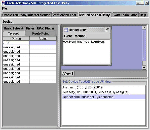
The user interface consists of the following components:
-
Left device tab for configuring and starting TeleDevice clients
-
Top right side contains multiple internal frames (one per Device)
-
Bottom right side message window for displaying messages
These components are illustrated in the following figure.
TeleDevice Test Utility Interface
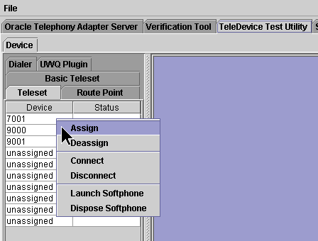
To configure a device, right click on it to open a menu and select an option: Assign, Deasign, Connect, Disconnect, Launch Softphone, or Dispose Softphone, as shown in the following illustration.
TeleDevice Configuration Options
TeleDevices
Each TeleDevice simulates a communication channel between an Oracle component and the third-party component, through the different SDK interfaces.
Teleset
Represents a Teleset device in Oracle Telephony Adapter Server, and simulates the channel between Oracle Telephony Manager and Oracle Telephony Adapter Server. Use this TeleDevice only for Standard or Advanced Integration.
Route Point
Represents a Route Point device in Oracle Telephony Adapter Server, and simulates the channel between Inbound Telephony Server and Oracle Telephony Adapter Server. This TeleDevice should only be used for Advanced Integration.
Dialer
Represents a Dialer device in Oracle Telephony Adapter Server, and simulates the channel between Advanced Outbound Dial Server and Oracle Telephony Adapter Server. Use this TeleDevice only for Standard or Advanced Integration with Oracle Advanced Outbound.
Basic Teleset
Represents a Teleset device in a third party provider's process, and simulates the channel between Media Provider Plug-in (in the Universal Work Queue Client process space) and the third party provider. Use this TeleDevice only for Basic Integration.
UWQ Plug-in
Represents an Oracle Universal Work Queue Client plug-in, and simulates the channel between Oracle Universal Work Queue Client, and the third-party provider. Use this TeleDevice only for Basic Integration.
Assigning TeleDevices
Each of the Oracle SDK Integrated Test Utility TeleDevice tabs has a table of ten rows. Each row represents a TeleDevice object. The TeleDevice objects must be associated to specific configurations to be able to connect to Oracle Telephony Adapter Server. This association is called "Assign" in the TeleDevice Test Utility. Developers can assign up to ten devices.
Assigning TelesetDevice
Use the following procedure to assign a TelesetDevice.
Log in
Not applicable
Responsibility
Not applicable
Prerequisites
Successfully start Oracle Telephony Adapter Server.
Steps
-
Select the TeleDevice Test Utility tab.
The Device page appears.
-
Select the Teleset sub tab.
-
Select the Device or Devices to assign.
-
Right click on the selected rows.
A menu appears.
-
Choose Assign.
The Assign Teleset window appears.
-
Enter the three extension numbers.
-
Click OK.
The TeleDevice Test Utility Log window displays the progress and completion of the assignments.
Assigning Route Point Device
Use the following procedure to assign a Route Point Device.
Log in
Not applicable
Responsibility
Not applicable
Prerequisite
Successfully start Oracle Telephony Adapter Server.
Steps
-
Select the TeleDevice Test Utility tab.
The Device page appears.
-
Select the Route Point sub tab.
-
Select the Device or Devices to assign.
-
Right click on the selected rows.
A menu appears.
-
Choose Assign.
The Assign RoutePoint window appears.
-
Enter the Route Point Number.
-
Optionally, if you want this route point to receive route requests, click Route Requested.
-
For Nortel Meridian with Intel CT Connect/NetMerge Call Processing Software only, in the Immediate Treatment field specify the immediate treatment of inbound calls arriving at this route point CDN (Control Directory Number). Enter ##R for ringback, ##M for music, or ##S for silence.
-
For Nortel Meridian with Intel CT Connect/NetMerge Call Processing Software only, if music treatment (##M) is specified in step 7, in the Music Route Number field specify the route number of a music source that is configured in the Meridian PBX. Enter # followed by a two-digit route number specified in hexidecimal. For example, if the music route number is 10, then enter #0A in the Music Route Number field.
-
Click OK.
The TeleDevice Test Utility Log window displays the progress and completion of the assignments.
Assigning Dialer
Use the following procedure to assign a Dialer.
Log in
Not applicable
Responsibility
Not applicable
Prerequisite
Successfully start Oracle Telephony Adapter Server.
Steps
-
Select the TeleDevice Test Utility tab.
The Device page appears.
-
Select the Dialer sub tab.
-
Select the Device or Devices to assign.
-
Right click on the selected rows.
A menu appears.
-
Choose Assign.
The Assign Dialer window appears.
-
Enter the Dialer ID and Vdu ID. Dialer ID is the ID to uniquely identify this Dialer Device. Vdu ID is the ID to identify the Vdu that the Dialer Device will control.
-
Press OK.
The TeleDevice Test Utility Log window displays the progress and completion of the assignments.
Assigning Basic Teleset
Use the following procedure to assign a Basic Teleset.
Log in
Not applicable
Responsibility
Not applicable
Prerequisite
Successfully start Oracle Telephony Adapter Server.
Steps
-
Select the TeleDevice Test Utility tab.
The Device page appears.
-
Select the Basic Teleset sub tab.
-
Select the Device or Devices to assign.
-
Right click on the selected rows.
A menu appears.
-
Choose Assign.
The Assign Basic Teleset window appears.
-
Enter the 3rd Party url, Agent ID, Teleset ID and Listener Port.
-
Click OK.
The TeleDevice Test Utility Log window displays the progress and completion of the assignments.
Assigning UWQ Plug-in
Use the following procedure to assign a UWQ Plug-in.
Log in
Not applicable
Responsibility
Not applicable
Prerequisite
Successfully start Oracle Telephony Adapter Server.
Steps
-
Select the TeleDevice Test Utility tab.
The Device page appears.
-
Select the UWQ Plug-in sub tab.
-
Select the Device or Devices to assign.
-
Right click on the selected rows.
A menu appears.
-
Choose Assign.
The Assign UWQ Plug-in window appears.
-
Enter the Agent ACD ID, Agent ACD Password, Agent ACD Queue, Listener Port, 3rd Party url, Reconnect Interval(sec), and Log Level.
-
Agent ACD ID: The Agent ACD ID to log in to the switch
-
Agent ACD Password: The Agent ACD Password to login into the switch
-
Agent ACD Queue: The Agent ACD Queue to log in to the switch
-
Listener Port: The Listener port for Basic SDK HTTP Listener
-
3rd Party url: Third-party URL implementing the Callout handling
-
Reconnect Interval: Number of seconds before the Basic SDK Plug-in tries to ping or reconnect to the third-party URL
-
Log Level: Error, warning, info, or verbose
-
-
Click OK.
The TeleDevice Test Utility Log window displays the progress and completion of the assignments.
Connecting and Disconnecting a TeleDevice
When a TeleDevice is assigned, the next step is to connect it to Oracle Telephony Adapter Server. Use the following procedure to connect a TeleDevice.
Note: Check that Oracle Telephony Adapter Server is started and running before connecting a TeleDevice.
Log in
Not applicable
Responsibility
Not applicable
Prerequisite
Assign at least one TeleDevice.
Steps
-
Select the appropriate TeleDevice tab: Dialer, UWQ Plug-in, Basic Teleset, Teleset, or Route Point.
-
Right click on the TeleDevice that you want to connect.
A menu appears.
-
Choose Connect.
-
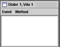
If the TeleDevice has connected successfully, a TeleDevice internal window appears, as shown in the following illustration.
TeleDevice Window
-
The message window shows that "RoutePoint X successfully connected" or "Teleset X successfully connected." Other TeleDevices display similar windows and messages.
Deassigning a TeleDevice
Removing a device assignment is called deassigning. Use the following procedure to deassign a TeleDevice.
Log in
Not applicable
Responsibility
Not applicable
Prerequisite
Assign at least one TeleDevice.
Steps
-
Select the appropriate TeleDevice tab (Dialer, UWQ Plug-in, Basic Teleset, Teleset, or Route Point).
-
Right click on the TeleDevice that you want to deassign.
A menu appears.
-
Select Deassign.
The configuration associated with the row is deassigned and removed.
Viewing Events
In the Event History window you can view up to thirty events that are sent by TeleDevice object implementations and cached.
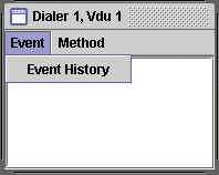
To open the Event History window, open a device message window (see Connecting and Disconnecting a TeleDevice) and select Event > Event History, as shown in the following illustration.
Event History Option
The Event History window opens, showing any event messages.
Invoking API Methods
You can invoke API methods for TelesetDevice, RoutePointDevice, DialerDevice, BasicTelesetDevice, and UWQPluginDevice.
Use the following procedures to invoke API methods for TeleDevices.
Log in
Not applicable
Responsibility
Not applicable
Prerequisites
Connect TeleDevice.
Steps
-
In an opened TeleDevice internal message window, select Method.
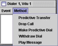
The Methods menu appears, as shown in the following illustration for the Dialer method.
Methods Options
-
Select a method.
For some methods, no result is apparent. For other methods, a window appears.
-
If a window appears, then enter the required information in the fields.
-
Click OK.
Route Point
RoutePointDevice invokes the following methods:
-
assignMediaItemId
-
routeCall
Teleset
TelesetDevice invokes the following methods:
-
makeCall
-
answerCall
-
releaseCall
-
holdCall
-
retrieveCall
-
loginAgent
-
logoutAgent
-
agentReadyOn
-
agentReadyOff
-
blindTransfer
-
consultationCall(Transfer)
-
completeTransfer
-
consultationCall(Conference)
-
completeConference
Dialer
DialerDevice invokes the following methods:
-
Predictive Transfer
-
Drop Call
-
Make Predictive Dial
-
Withdraw Dial
-
Play Message
UWQ Plug-in
UWQ Plug-in invokes the following methods:
-
Make Call
-
Next Work
-
Cancel Work Request
-
Login Agent
-
Logout Agent
Basic Teleset
Basic Teleset invokes the following methods:
-
Make Call
-
Agent Ready
-
Agent Not Ready
-
Login Agent
-
Logout Agent
-
Register Agent
-
Unregister Agent
Disconnecting a TeleDevice
Use the following procedure to disconnect a TeleDevice.
Log in
Not applicable
Responsibility
Not applicable
Prerequisite
Connect a TeleDevice.
Steps
-
Select the appropriate TeleDevice tab (Dialer, UWQ Plug-in, Basic Teleset, Teleset, or Route Point).
-
Right click on the TeleDevice that you want to disconnect.
A menu appears.
-
Choose Disconnect.
Launching the Softphone
To verify the softphone functionality, use the following procedures to launch and close the softphone.
Log in
Not applicable
Responsibility
Not applicable
Prerequisite
Assign a Teleset Device.
Steps
-
Select the TeleDevice Test Utility tab > Teleset sub tab.
-
In the Device column, right click on the applicable, assigned teleset device number.
A menu appears.
-
Select Launch Softphone.
The loginAgent window appears.
-
Enter the acdAgentId, acdAgentPassword and acdQueue.
-
Click OK.
The softphone interface opens.
Closing the Softphone
Use the following procedure to close the softphone.
Log in
Not applicable
Responsibility
Not applicable
Prerequisite
None
Steps
-
Select the TeleDevice Test Utility tab > Teleset sub tab.
-
In the Device column, right click on the applicable teleset device number.
A menu appears.
-
Select Dispose Softphone.
The Agent Logout window appears.
-
Click OK.
The softphone interface closes.
Switch Simulator
The Switch Simulator is one of the Interaction Center server processes that is used in demonstration environments where a real switch is not available. The switch simulator supports teleset and route point functions, and three integration levels: Basic, Standard and Advanced.
In Standard and Advanced Integration, the Switch Simulator acts as a simulated switch that listens for Oracle Telephony Adapter's Server's teleset and route point commands (makeCall) and fake events (callRinging) to the appropriate teleset or route point extensions.
In Basic Integration, the Switch Simulator acts as a third party HTTP listener that listens for callouts from the Basic Telephony SDK plug-ins and fake HTTP and XML events to the appropriate Basic Telephony SDK plug-ins.
The Switch Simulator interface consists of two tabs:
-
Server tab, to start and stop the Switch Simulator server, and to configure and view logs.
-
Configure tab, the extension configuration for starting the Switch Simulator server.
Starting and Stopping the Switch Simulator
Use the following procedures to start or stop the Oracle SDK Integrated Test Utility Switch Simulator.
Log in
Not applicable
Responsibility
Not applicable
Prerequisite
Configure the Switch Simulator.
Steps
-
In the Oracle SDK Integrated Test Utility, select the Switch Simulator tab > Server sub tab.
The Server page opens.
-
Do one of the following:
-
To start the Switch Simulator, click Start.
The Switch Simulator launches as a background Java process, and starts by using the current extension configuration.
-
To stop the Switch Simulator, click Stop.
The Switch Simulator background process terminates.
-
Configuring Switch Simulator Server Settings
Use the following procedure to configure the Switch Simulator server settings.
Log in
Not applicable
Responsibility
Not applicable
Prerequisites
None
Steps
-
In the Oracle SDK Integrated Test Utility, select the Switch Simulator tab > Server sub tab.
The Server page opens.
Note: Any changes you make while the Switch Simulator is running do not take effect until you stop and restart the Switch Simulator.
-
Choose the extent of detail in the Switch Simulator Log by selecting a logging level:
-
error: Print only error messages.
-
warning: Print error and warning messages.
-
info: Print error, warning and informational messages.
-
verbose: Print all messages.
-
-
Optionally, you can configure the directory of the log file by typing the directory path into the Log Directory text box. To name the log file, use the pattern swsimyyyymmdd_hhmmss.log. The default directory is oracle/apps/cct/bin/log.
-
Configure the port number of the Switch Simulator by entering the port number in the Server Port field. This is the port number that Oracle Telephony Adapter Server uses to communicate with the Switch Simulator for Standard and Advanced Integration.
-
Configure the port number of the Switch Simulator HTTP listener by entering the port number in the HTTP Server Port text box. This is the port number that UWQ Client uses to communicate with the Switch Simulator in Basic Integration.
-
Select File > Save to save the configurations.
Configuring Simulated Extensions and Route Points
Use the following procedure to configure simulated extensions and route points.
Log in
Not applicable
Responsibility
Not applicable
Prerequisites
None
Steps
-
Select the Switch Simulator tab > Configure sub tab.
The Extensions and Route Points page appears.
-
In the Extension Range fields, enter extension ranges 1 through 3 for simulated telesets.
-
In the three Route Point fields, enter route point extensions for simulated route points.
-
Select File > Save to save the configurations.
Configuring the Switch Simulator for Standard or Advanced Integration
Use the following procedure to configure the Oracle SDK Integrated Test Utility's Oracle Telephony Adapter Server settings for Standard Integration or Advanced Integration.
Log in
Not applicable
Responsibility
Not applicable
Prerequisites
-
Configure Oracle Telephony Adapter Server to connect to the Switch Simulator.
-
Configure the Switch Simulator.
Steps
-
Select the Oracle Telephony Adapter Server tab > Middleware sub tab.
The Middleware page opens.
-
From the Middleware Type list, select Java Adapter.
-
In the Factory Class Name field, enter
oracle.apps.cct.sdk.sample.advanced.SampleTeleDeviceFactory
-
In the CTI Server IP Address 1 field, enter the IP Address of the machine on which the Switch Simulator starts.
-
In the CTI Server IP Port 1 field, enter the Server Port (not the HTTP Server Port) of the Switch Simulator.
-
Select the TeleDevice Test Utility tab > Device sub tab.
The Device page opens.
-
In Teleset Device fields 1 through 3, assign extensions within the range that are the same as those configured in the Switch Simulator.
-
In the Route Point Status fields, assign Route Point Number to be one of the Route Point extensions that are configured in the Switch Simulator.
-
Select File > Save to save the configuration.
Configuring the Switch Simulator for Basic Integration
When developing Basic Integration, the Switch Simulator acts as the third-party provider that listens for callouts from UWQ Client. The Basic Teleset and UWQ Plug-in TeleDevices can be used to simulate connectivity between UWQ Client and the Switch Simulator.
Use the following procedure to configure the Oracle SDK Integrated Test Utility's Switch Simulator for Basic Integration.
Log in
Not applicable
Responsibility
Not applicable
Prerequisites
Configure the Switch Simulator.
Steps
-
Select the TeleDevice Test Utility tab > Device sub tab.
The Device page opens.
-
Do either a or b:
-
Select the Basic Teleset sub tab.
-
Right click on a Device that you want to configure.
A menu appears.
-
Select Assign.
The Assign Basic Teleset window opens.
-
In the 3rd Party url field, enter
http://<IP Address of Switch Simulator>:<HTTP Server Port of Switch Simulator>/
-
-
Select the UWQ Plug-in tab.
-
Right click on a Device that you want to configure.
A menu appears.
-
Select Assign.
The Assign UWQ Provider Plug-in window opens.
-
In the 3rd Party url field, enter
http://<IP Address of Switch Simulator>:<HTTP Server Port of Switch Simulator>/
-
-
Javadoc
Javadoc is a facility provided within the Java Development Kit that produces HTML documentation from a program. Javadoc reads the source code and parses specially formatted and positioned comments into documentation.
To access the Javadoc for Oracle Telephony Adapter SDK, select the Help tab in the Oracle Telephony SDK Integrated Test Utility.