Your NAT Scenario
When building security policies using NAT, define the security policy rules in terms of internal addresses. All packets that are destined for external addresses used in NAT must be routed to the Screen.
Note -
If you use static NAT to map a machine's address, a machine on any other network can initiate traffic to that machine, given a properly defined reverse rule.
In routing mode (unlike stealth mode), the Screen does not automatically answer ARP requests for destination address. Consequently, the Screen must either route to a separate network that has a destination address, or a proxy ARP entry must be configured manually.
Static NAT is a one-to-one mapping of the internal address to an external address. Dynamic NAT is many-to-one or many-to-few mapping of internal addresses to an external address.
For more information on NAT and the possible set up, see "Network Address Translation" in SunScreen 3.2 Administrator's Overview. For an example that uses NAT, see SunScreen 3.2 Configuration Examples manual.
Note -
In cases where NAT will occur between the Administration station and the Screen, do not include the address of a remote Administration Station in any of your NAT rules.
If Centralized Management is in place, each NAT rule must be associated explicitly with the Screen to which it applies.
To Manually Add an ARP Entry
For networks that attach to the Screen on the inside and have NAT mappings applied, use the following command.
This is recommended for any network on which there are addresses to which you want to allow public access.
# arp -s IP_Address ether_address pub |
You must add this entry each time you reboot the Screen, so you may want to modify a startup script to do this automatically when you reboot.
Note -
This entry is not necessary in stealth mode.
The following information describes how to use the administration GUI. Chapter 10, Using the Command Line Interface contains information about the command line interface.
To Define NAT Rules
When you design a static NAT mapping, be sure that the ranges and groups used in the Source and Translated Source fields and the ranges and groups used in the Destination and Translated Destination fields are exactly the same size.
-
Execute the steps in "To Modify Rules".
-
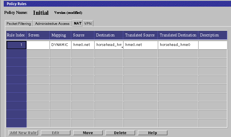
Select the NAT tab in the Policy Rules area.
The Network Address Translation area is displayed.

-
Click Add New Rule below the Network Address Translation area.
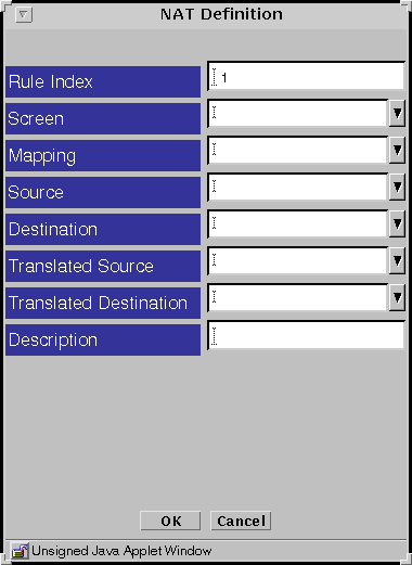
The NAT Definition dialog box is displayed.

-
Select the Screen that should use NAT mapping.
The default is NAT applied to the policies of all Screens.
-
Select all four addresses in the NAT Definition dialog box.
-
Click the OK button.
-
Repeat the previous steps until you have configured all the rules as required.
-
Click the Save Changes button to save the edited mappings.
You must click the Activate button for the changes take effect.
In most cases, when you define a static mapping, the internal address and external address are both single addresses.
To Edit the NAT Rules
-
Execute the steps in "To Modify Rules".
-
Select the NAT tab in the Policy Rules area.
The Network Translation area appears.

-
In the Mapping field, select the mapping on the table that you want to edit.
-
Click the Edit button below the Network Address Translation area.
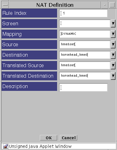
The NAT Definition dialog box for that mapping appears.

-
Select the type of mapping that you want in the Mapping field.
-
Select the address that you want in the Source field.
The source address in the Source field should match the packet.
-
Select the address that you want in the Destination field
The destination address in the Destination field should match the packet.
-
Select the translated source that you want.
-
Select the translated destination that you want.
-
Click the OK button of the NAT Definition dialog box to save your edits.
-
Repeat the previous steps until you have edited all the mappings as required.
-
Click the Save Changes button to save the edited mappings to a file.
You must click the Activate button for the changes take effect.
- © 2010, Oracle Corporation and/or its affiliates
