Chapter 1 Overview of ChorusOS Operating System and its Initialization
This section describes porting and the mechanisms that you need to understand to be able to write a new board support package.
Introduction to Porting ChorusOS Operating System
The Sun Embedded Workshop software provides reference implementations of the ChorusOS operating system as a set of binary products, one for each of the supported target families of processors. The processors on the boards in each target family are electronically different but are identical in their interactions with the operating system.
The binary product for a given family consists of:
-
A set of generic runtime binaries
-
A set of boot program sources
-
A set of device driver sources
The generic runtime is compiled for the given family of processors. For example, the ChorusOS operating system for PowerPC generic runtime will work with the PowerPC 750 and 7400 processors. The generic runtime needs additional board-specific components in order to produce a system that can boot and do useful work. In particular, you need to add a boot program and a set of device drivers.
The set of items that you need to add to support a specific board is called the Board Support Package (BSP).
The set of boot programs and device drivers provided with the binary product will work with the reference platforms. However, you may need to customize these components to, for example, optimize your system. The BSP source for the target family that you have installed is included in the binary product, therefore allowing you to modify it. In addition the BSP source for the other supported processor families is provided in a separate package for you to refer to (see the corresponding ChorusOS Target Family Guide) .
When you have selected the board that you wish to port ChorusOS to, you will need to identify the reference implementation from the supported BSP source that most closely resembles your target board. Use this reference implementation as the basis for your BSP, porting the components as necessary.
To create a BSP for a specific target board, you need to provide four components:
-
A bootstrap program
-
A reboot program
-
A driver for the host bus bridge of the board (if not already available)
-
Drivers for the board's other devices (if not already available)
The boot program is heavily dependent on the board and will need to be adapted or rewritten. Whereas the host bus driver is dependent on the target family and therefore may be used for boards in the same target family (maybe with some adaptation). You may be able to reuse existing drivers for managing the board's other devices, using the Sun Embedded Workshop device driver framework. For more information on writing device drivers and using the device driver framework see section "Overview of Creating a New Device/Bus Driver".
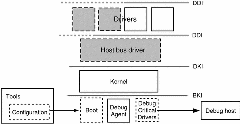
In Figure 1-1, the elements drawn with dotted lines are the elements that must be modified or replaced when porting a ChorusOS operating system. The elements shown in gray with dotted lines may need to be modified or replaced. Finally the elements shown with unbroken lines are not usually changed when porting the system to another target board.
Figure 1-1 Component Architecture

The figure also shows the interfaces between each of the component layers. DDI stands for the device driver interface. DKI stands for the device-kernel interface. BKI stands for the boot-kernel interface. For more information on these interfaces see "Device Driver Interface (DDI)", "Driver/Kernel Interface (DKI)" and "The Boot-Kernel Interface".
Driver Framework Architecture Overview
In the ChorusOS operating system, a driver entity is a software abstraction of the physical bus or device. Creating a device driver using the Driver Framework allows the device or bus to be represented to, and managed in the ChorusOS operating system. The hierarchical structure of the driver software within the ChorusOS operating system mirrors the structure of the physical device/bus.
Each device or bus is represented by its own driver. A driver's component code is linked separately from the microkernel as a supervisor actor, with the device-specific code strongly localized in the corresponding device driver.
Note that a supervisor actor containing a driver code should be considered a container only rather than a real supervisor actor with its own execution personality. Driver code runs either in the interrupt execution environment (typically up-calls) or in the driver client execution environment (typically down-calls). In other words, the driver component code logically belongs to the current driver client (microkernel module or supervisor actor).
Note -
The driver is always considered a trusted system component.
This means that the Driver Framework defines a structure and principle. Since the driver is a trusted system component, care should be taken to ensure that drivers are written in conformance with the framework. Only the APIs that are authorized for drivers can be used (see API(5FEA)). Even if the task of creating drivers with the Driver Framework seems relatively simple. Some checking can be done when building in debug mode but this cannot replace writing the driver in compliance with the Driver Framework.
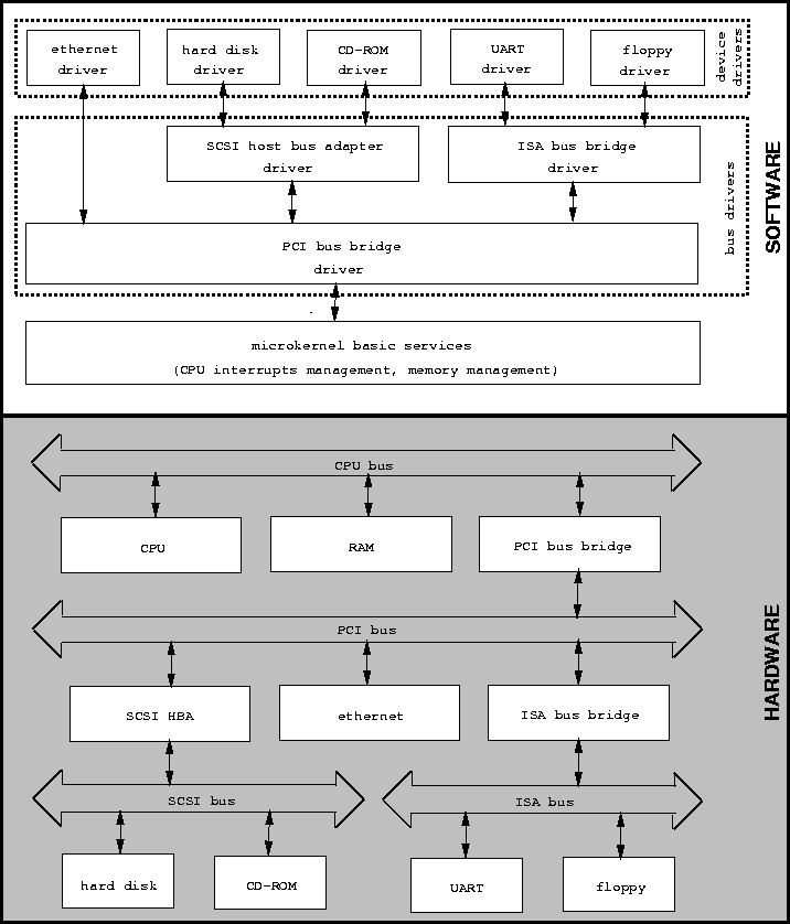
Driver components are organized, through a service-provider/user relationship, into hierarchical layers which mirror the hardware bus/device connections.
Interactions between these drivers are implemented via simple indirect function calls (down-calls and up-calls).
Figure 1-2 Bus/Device Hierarchy, in Hardware and Software

Overview of ChorusOS Boot Process
There are three stages to booting ChorusOS on the target system:
-
Power-up initialization
-
Loading the system image
-
The initialization of the ChorusOS operating system, including the system drivers
Power-up Initialization
When the board is powered up or reset, the processor starts executing code at a fixed address. This code sets up the minimum hardware environment required by the system loader. The initialization code (the initial loader) is stored in non-volatile physical memory.
Loading the System Image
The last action of the power-up initialization code is to hand control to the initial loader which loads the system image into physical memory and jumps to the image entry point.
If the system image is already stored in non-volatile memory on the board, the initial loader is not required, and the initialization code terminates by jumping to the entry point of the system image.
The initial loader may either be the firmware provided by the board, or the ChorusOS Boot Monitor (see bootMonitor(1M)).
Most development boards are provided with a standard firmware power-up initialization code and loader in PROM. This firmware is able to download a system image from a local device or from the network (for example, PPC-Bug firmware on platforms in the PowerPC target family). Sun Embedded Workshop provides tools that build the ChorusOS system image in the format required by the firmware loaders supported.
For some target families it is also possible to use bootMonitor (instead of the board firmware) as the initial loader. It downloads the ChorusOS system image from a local device or from the network. See the ChorusOS 5.0 Installation Guide.
The bootMonitor utility is implemented as an application on top of a minimal ChorusOS configuration.
The Initialization of the ChorusOS Microkernel and OS
The ChorusOS operating system boots from the system image. The system image contains binary executable files of the bootstrap program, debug agent, microkernel, drivers, OS servers and applications. It can also contain a set of data files such as networking configuration files.
System image files are organized in one or more memory banks. Each memory bank can be formatted as a file system volume (for example, FAT12) and exported through the microkernel API as a memory device. Thus a system image file can be viewed as a file in a file system volume on a memory device.
The ChorusOS operating system is initialized in two stages:
-
microkernel initialization
-
OS service initialization
The microkernel is the minimal ChorusOS operating system comprising the microkernel and the built-in drivers. The bootstrap program starts the microkernel. The microkernel then starts the built-in drivers.
The operating system (OS) is implemented on top of the microkernel as a set of actors that provide services such as file systems and networking protocols. ChorusOS actors are defined and detailed in "Using Actors" in ChorusOS 5.0 Application Developer's Guide.
The microkernel starts the OS services by creating the initial subset of OS actors from the system image binary files. The OS can then activate additional system services by loading actors from files located on the system image memory, or from local or remote devices.
Overview of ChorusOS Reboot Process
The ChorusOS operating system supports three system reboot scenarios:
-
Cold reboot
-
Hot reboot
-
Boot of the system image loaded by the ChorusOS bootMonitor (equivalent to booting a new system image that is loaded by the one that is running).
A system reboot can be initiated by either the operating system sysShutdown() call, by the system failure recovery procedure, or by some special system applications such as bootMonitor.
All system reboot scenarios will use the sysReboot() microkernel call. sysReboot() calls the emergency stop services of all registered drivers and then transfers control to a board-specific reboot program.
When performing a cold reboot, the reboot program will reset the hardware and the system lifecycle will be restarted from the power-up initialization program.
In the case of a hot reboot, the system boots from the system image, originally deployed by the cold reboot (that is, it boots from itself). For further information on this, see the Chapter 5, The ChorusOS Reboot Program.
Finally, if one ChorusOS system (that is, bootMonitor) boots another ChorusOS system (that is, the system image loaded by bootMonitor) then the new system image is installed at the required address and the reboot program will jump to it. For further information on this, see Chapter 5, The ChorusOS Reboot Program.
For more information on booting a ChorusOS operating system, see Chapter 4, The ChorusOS Boot Program.
- © 2010, Oracle Corporation and/or its affiliates
