Installing PCI-SCI Cluster Interconnect Hardware
Table 3-2 lists procedures for installing PCI-SCI-based cluster interconnect hardware. Perform the procedures in the order that they are listed. This section contains a procedure for installing cluster hardware during an initial cluster installation, before Sun Cluster software is installed.
Table 3-2 Task Map: Installing PCI-SCI Cluster Interconnect Hardware|
Task |
For Instructions, Go To |
|---|---|
|
Install the PCI-SCI transport cables (and PCI-SCI switch for four-node clusters). |
How to Install PCI-SCI Transport Cables and Switches
-
If not already installed, install PCI-SCI host adapters in your cluster nodes.
For the procedure on installing PCI-SCI host adapters and setting their DIP switches, see the documentation that shipped with your PCI-SCI host adapters and node hardware.
Note -Sbus-SCI host adapters are not supported by Sun Cluster 3.0. If you are upgrading from a Sun Cluster 2.2 cluster, be sure to remove any Sbus-SCI host adapters from the cluster nodes or you may see panic error messages during the SCI self test.
-
Install the PCI-SCI transport cables and optionally, switches, depending on how many nodes are in your cluster:
-
A two-node cluster can use a point-to-point connection, requiring no switch. See Figure 3-3.
Connect the ends of the cables marked "SCI Out" to the "O" connectors on the adapters.
Connect the ends of the cables marked "SCI In" to the "I" connectors of the adapters as shown in Figure 3-3.
Figure 3-3 Typical Two-Node PCI-SCI Cluster Interconnect

-
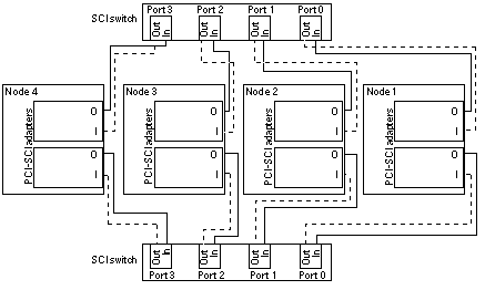
A four-node cluster requires SCI switches. See Figure 3-4 for a cabling diagram. See the SCI switch documentation that came with your hardware for more detailed instructions on installing and cabling the switches.
Connect the ends of the cables that are marked "SCI Out" to the "O" connectors on the adapters and the "Out" connectors on the switches.
Connect the ends of the cables that are marked "SCI In" to the "I" connectors of the adapters and "In" connectors on the switches. See Figure 3-4.
Note -Set the Unit selectors on the fronts of the SCI switches to "F." Do not use the "X-Ports" on the SCI switches.
Figure 3-4 Typical Four-Node PCI-SCI Cluster Interconnect

-
Troubleshooting PCI-SCI Interconnects
If you have problems with your PCI-SCI interconnect, check the following items:
-
Verify that the LED on the PCI-SCI host adapter is blinking green rapidly. If it is not, refer to the documentation that came with your host adapter for detailed LED interpretations and actions.
-
Verify that the PCI-SCI host adapter card DIP switch settings are correct, as described in the documentation that came with your PCI-SCI host adapter.
-
Verify that the PCI-SCI cables are correctly connected so that the PCI-SCI cable connectors that are marked "SCI In" are connected to the "I" ports on the PCI-SCI adapter cards and to the "In" ports on the SCI switches (if you are using switches).
-
Verify that the cables are correctly connected so that the PCI-SCI cable connectors that are marked "SCI Out" are connected to the "O" ports on the PCI-SCI adapter cards and to the "Out" ports on the switches (if you are using switches).
-
Verify that the PCI-SCI switch Unit selectors are set to "F."
Where to Go From Here
You install the cluster software and configure the interconnect after you have installed all other hardware. To review the task map for installing cluster hardware, see "Installing Sun Cluster Hardware".
- © 2010, Oracle Corporation and/or its affiliates
