Chapter 3 Configuring the SCI Network Interface
This chapter explains how to configure the SCI network interface in a Sun HPC 3.0 cluster. It covers the following procedures:
-
Creating a temporary network map for later reference - See "Create a Temporary Network Map for Later Reference"
-
Creating the SCI configuration file, sci_config.hpc - See "Create sci_config.hpc"
-
Running sm_config to initialize the SCI network interface - See "Propagate the SCI Configuration"
-
Verifying the rank of the SCI interfaces - "Verify the Rank of the SCI Interface"
-
Rebooting the cluster nodes - "Reboot Nodes"
The first section, "Preconditions", describes a few conditions that must be in effect before the SCI interface can be configured.
Preconditions
Ensure that the conditions described below are in effect before proceeding with the SCI setup procedure.
SCI Network Hardware Must Be Installed
The SCI network hardware must already have been installed.
ClusterTools 3.0 Software Must Be Installed
The Sun HPC ClusterTools 3.0 software must be installed on the cluster--either on an NFS server or locally on each node. If this has not yet been done, refer to the Sun HPC ClusterTools 3.0 Installation Guide for instructions.
If you will be using the LSF suite as the cluster's workload manager, the LSF components must be installed before the ClusterTools software.
Verify that the following Sun HPC ClusterTools 3.0 packages are present.
-
SUNWsci
-
SUNWscid
-
SUNWscidx - required only on clusters with 64-bit Solaris 7
-
SUNWsma
-
SUNWsmax - required only on clusters with 64-bit Solaris 7
-
SUNWrsmop
-
SUNWrsm
These SCI and RSM packages may not be present if, during installation of the ClusterTools 3.0 software, the installer responded "No" when asked if SCI packages should be installed. If they are not present, they must be installed.
The installation GUI (graphical user interface) includes an option for installing the SCI-related packages exclusively. See the Sun HPC ClusterTools 3.0 Installation Guide for more information.
If any of these packages were installed from another source, you must remove them and install the packages provided on the Sun HPC ClusterTools 3.0 software release.
Caution for NIS+ Users
sm_config may have trouble contacting other node in the cluster in an NIS+ environment. By default, the NIS+ version of /etc/nsswitch.conf specifies the services entry as: nisplus [NOTFOUND=return] files. Since the /etc/services file is modified and used by SUNWsma and other packages, the /etc/nsswitch.conf entry should be as follows:
services: files nisplus |
Place the term files first before other entries.
Create a Temporary Network Map for Later Reference
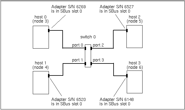
Before you create the SCI configuration file, sci_config.hpc, sketch out a rough map of the physical network connections and identify each SCI adapter by its serial number. Look on the connector panel of the node. An adapter's serial number will be printed on a white label in the upper left corner of the adapter`s connector. It is usually a four- or five-digit number.
Figure 3-1 shows an example of a temporary map of a four-node configuration without striping--that is, with one SCI network adapter connection per node.
This information will make it easier to verify that the adapter ID values specified in the sci_config.hpc file match the actual values assigned by the device driver. Instructions for using this map are provided in the section "SCI Configuration Templates".
Figure 3-1 Sample Temporary Map of a Four-Node, Nonstriped Configuration
Create sci_config.hpc
The SCI configuration procedure reads network mapping information from the configuration file /opt/SUNWsma/sci_config.hpc, which you create.
SCI Configuration Templates
The Sun HPC ClusterTools 3.0 software release includes the following SCI configuration templates to simplify the creation of sci_config.hpc. Each template represents a supported SCI network topology.
-
sma2.hpc - Two nodes connected directly by a single SCI station cable. There is no intervening SCI switch. Because this configuration uses only one network interface per node, it does not support message striping.
-
sma3.hpc - Three nodes connected through an SCI switch. Each node is connected to the switch by a single station cable. Consequently, message striping is not supported.
-
sma4.hpc - Four nodes connected through a single SCI switch. Each node is connected to the switch by a single station cable. Again, message striping is not supported.
-
sma2-2stripes.hpc - Two nodes connected directly by two SCI station cables. There is no intervening SCI switch. Because both nodes have two network interfaces, messages can be striped across both cables.
-
sma4-2stripes.hpc - Four nodes connected through two SCI switches via two station cables per node. Because each node has two network interfaces, striping is supported. Two SCI switches are needed because each switch has only four ports.
These templates are in /opt/SUNWhpc/bin/Install_Utilities/config_dir.
Editing a Configuration Template
Copy the applicable template to /opt/SUNWsma/sci_config.hpc. For example, to create a configuration file for the two-node striped topology,
# cd /opt/SUNWsma # cp /opt/SUNWhpc/bin/Install_Utilities/config_dir/sma2-2stripes.hpc sci_config.hpc |
Use the sma4-2stripes.hpc template for creating a three-node, striped configuration.
Next, edit sci_config.hpc. Every template type is organized into eight sections. Instructions for editing each section are provided below.
Section 1 - Cluster Configuration Type
Section 1 asks you to specify the type of cluster you have; you are given the options: SC (Sun Cluster) or HPC. Enter HPC, as follows:
Cluster is configured as = HPC
SC is not a valid entry for clusters running Sun HPC ClusterTools software.
Section 2 - Host Names
List all of the nodes in the cluster by replacing <host_namen> placeholders with the host names of the cluster's nodes. For example, if your cluster contains the nodes: node3, node4, node5, and node6, Section 2 should look like this:
HOST 0 = node3
HOST 1 = node4
HOST 2 = node5
HOST 3 = node6
The nodes can be listed in any order.
Section 3 - Number of Switches
Specify the number of SCI switches in the cluster. This will be determined by which network topology you implement, as follows:
-
Two-node cluster - either nonstriped or striped, set
Number of Switches in cluster = 0
-
Three- or four-node cluster - nonstriped, set
Number of Switches in cluster = 1
-
Three- or four-node cluster - striped, set
Number of Switches in cluster = 2
Section 4 - Number of Direct Links
Specify the number of unswitched node-to-node connections your cluster has. Again, this will depend on which topology you implement, as follows:
-
Two-node cluster - nonstriped, set
Number of Direct Links in cluster =
1
-
Two-node cluster - striped, set
Number of Direct Links in cluster =
2
-
Three- or four-node cluster - either nonstriped or striped, set
Number of Direct Links in cluster =
0
Section 5 - Number of Ring Connections
Ring connections are not supported by Sun HPC ClusterTools 3.0 software. Therefore, always specify
Number of Rings in cluster = 0
Section 6- Adapter Information
List all SCI adapters in the cluster and describe the connection details for each.
Use a separate line for each adapter description. The format for describing unswitched connections is
host n :: adp n is connected to = link
n :: endpt n
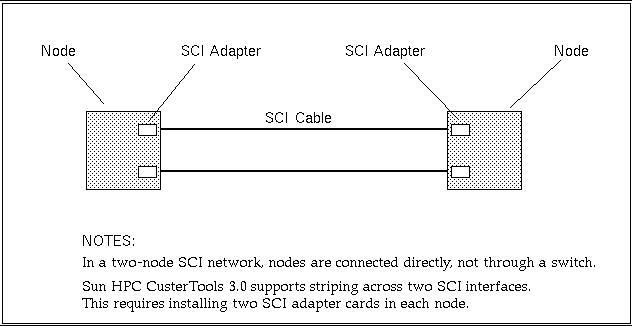
When no switch is used, an adapter (adp) is connected to a particular endpoint (endpt n) on a particular channel (link n). See Figure 3-2 and Figure 3-3.
Each adapter has its own endpoint. That is why two different endpoints are shown on one link.
Figure 3-2 Two-Node Nonstriped Configuration

Figure 3-3 Two-Node, Striped Configuration
The format for describing switched connections is slightly different.
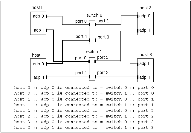
host n :: adp n is connected to = switch
n :: port n
Here, an adapter is connected to port n of switch n. Figure 3-4 through Figure 3-7 show examples of this format.
Figure 3-4 Three-Node, Nonstriped Configuration
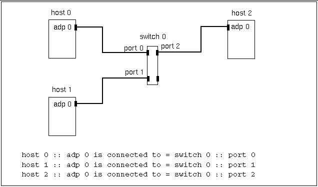
Figure 3-5 Three-Node, Striped Configuration
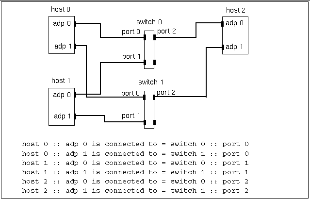
Figure 3-6 Four-Node, Nonstriped Configuration
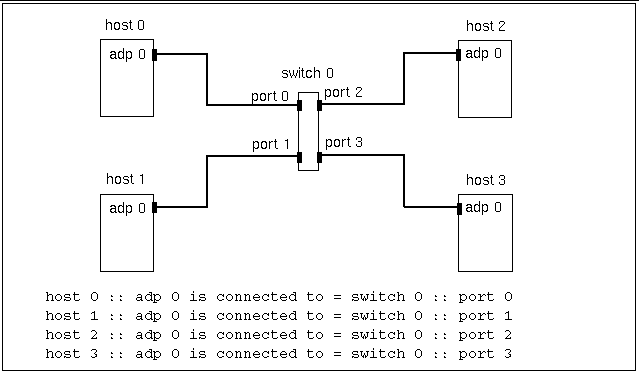
Figure 3-7 Four-Node, Striped Configuration
Adapter ID values are assigned automatically by the device driver. Initially, the device driver assigns ID 0 to the adapter installed in the lowest-numbered SBus slot, ID 1 to the adapter in the next higher-numbered slot, and so forth. ID value assignments are always consecutive, even if the adapters are not installed in adjacent slots. Consequently, if adapter cards are not installed in adjacent slots, adapter ID values do not necessarily correspond to SBus slot numbers.
Once an ID value is assigned, it will not be reassigned, even if the adapter to which it was originally assigned is removed.
Because a ID values do not necessarily correspond to SBus slot numbers, the adp n values that you assign in the sci_config.hpc file may not match the actual ID assignments made by the device driver. For this reason, you may need to revise this adapter connection description (that is, the contents of Section 7) to match the actual adapter connections.
This is why you were advised to make the temporary map of the physical network layout. Instructions for ensuring that the sci_config.hpc file matches the actual adapter ID values are provided in "Compare sm_config Output With Contents of sci_config.hpc"
Section 7 - Network IP Addresses
Specify the first three octets of the IP address of each link or switch. For example, for a two-node, striped configuration,
Network IP address for Link 0 = 204.71.29
Network IP address for Link 1 = 204.71.15
An example of a four-node, nonstriped configuration might be
Network IP address for Switch 0 = 204.101.30
Section 8 - Netmask Value
Specify the netmask to be used for the private SCI subnet. For example,
Netmask = e0
This netmask value will support up to eight subnets with up to 30 hosts per subnet.
Propagate the SCI Configuration
Perform the following steps on the node that contains the sci_config.hpc file.
Run sm_config
Go to /opt/SUNWsma/bin and run the SCI setup program, sm_config.
If possible, do this from a console terminal so you can see the output generated by sm_config. If this is not possible, examine the output in /var/adm/messages. The following example shows the output that would be generated for the four-node, nonstriped sample configuration shown in Figure 3-1.
# cd /opt/SUNWsma/bin # sm_config -f ../sci_config.hpc For Host #0 (node3), adapter details :- Adp #0 :- serial no = 6269; bus slot = 0; For Host #1 (node4), adapter details :- Adp #0 :- serial no = 6520; bus slot = 0; For Host #2 (node5), adapter details :- Adp #0 :- serial no = 6527; bus slot = 0; For Host #3 (node6), adapter details :- Adp #0 :- serial no = 6148; bus slot = 0; Press Return to continue: |
Do not press Return yet. Instead, go to the next section.
Compare sm_config Output With Contents of sci_config.hpc
Compare the list of serial numbers in the sm_config output with the serial numbers in the temporary map you made of the actual network configuration. Verify that the adapter IDs and connection details you entered in Section 6 of sci_config.hpc correspond to your temporary network map. If not, change the contents of sci_config.hpc to correspond to physical configuration described by the temporary map.
When examining the sm_config output, also look for any error messages reported by sm_config or sm_configd.
If the sm_config output conflicts with Section 6 of the sci_config.hpc file, stop execution of sm_config (press Control-C) and correct the configuration file. Then run sm_config again and compare its output with sci_config.hpc again.
When the contents of the sci_config.hpc file are confirmed by the sm_config output, press Return to allow sm_config to complete execution.
Verify the Rank of the SCI Interface
Look in the file hpc.conf and change the default ranking of the SCI interface to give it the highest priority. That is, give it a lower number in the RANK column than any other interface listed in the file--for example, change its rank to 1.
If you don't know the hpc.conf file's location, do one of the following:
-
LSF - If your cluster is running LSF, open the LSF file /etc/lsf.conf. The LSF_CONFDIR entry in lsf.conf identifies the directory containing hpc.conf.
-
CRE - If your cluster is running the CRE, look in /opt/SUNWhpc/conf/hpc.conf.
Add Variable to sci.conf File
Add the following line to /usr/kernel/drv/sci.conf.
max-vc-number = 1024;
Reboot Nodes
Reboot all the nodes in the cluster.
Next, verify that the SCI network is correctly configured. Instructions for verifying the network are provided in Chapter 4, Verify That the Network Is Functional .
- © 2010, Oracle Corporation and/or its affiliates
