Chapter 2 About X.25
This section provides an overview of X.25 concepts. None of the information in this chapter is specific to Solstice X.25 9.2--it applies to any implementation conforming to the X.25 Recommendations. Understanding the concepts explained here will help you make better use of the Solstice X.25 9.2 product.
Refer to Chapter 1, About Solstice X.25 for an overview of Solstice X.25 9.2.
The X.25 protocol suite enables the exchange of data between X.25 systems across Packet Switched Data Networks (PSDN), and Local Area Networks. Systems running one implementation of X.25, for example Solstice X.25, can exchange data with systems running any other implementation of X.25.
X.25 Overview
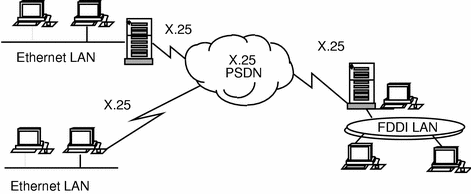
It is conventional to represent an X.25 network as a cloud, as in Figure 2-1.
Figure 2-1 X.25 Overview

As Figure 2-2 shows, X.25 defines the way the interface between a system running X.25 (often referred to as a DTE) and a system providing a network connection (often referred to as a DCE) works. There is almost always a modem between the DTE and the DCE to handle the physical connection. However, this is transparent to X.25. X.25 does not define the means of transmission that should be used between the two DCEs.
Figure 2-2 X.25 Detail

Dial-Up and Leased Lines
When connecting to a public network, for example one administered by a phone company, you must choose between using dial-up access and leased lines.
A leased line is a line allocated to you by the network's administration. You pay for exclusive use of this line and for it to be configured to your specification. You can only change the characteristics of this line in consultation with your network provider. For leased lines, the service provider typically provides a suitable modem for connecting your DTE to the network.
Dial-up access means that there is no particular line allocated for your use. When a DTE needs to access the public network, it uses a modem to place a call to the network. This means that there are no rental or set-up charges as there are with a leased line; charging is done on a per-call basis. Most dial-up services use the X.32 protocols to provide a degree of authentication, so the network knows the call is coming from an approved user.
Permanent and Switched Virtual Circuits
The end-to-end (DTE to DTE) connection provided by the X.25 Recommendations is called a virtual circuit. This is not a physical connection between the DTEs; it is a logical communication path. Public networks offer two types of virtual circuit--permanent and switched. Typically a subscription consists of a mixture of the two.
A permanent virtual circuit (PVC) is a permanent association between two DTEs that is established when a user subscribes to a public network. Many providers charge a flat rate per month for a PVC in addition to the charge per unit of data.
A switched virtual circuit (SVC) is a temporary association between two DTEs that exists only for the duration of a call. Most providers charge per minute for an SVC in addition to a charge per unit of data.
In general, SVCs are less expensive than PVCs unless two end-points need to be in constant communication, but this varies between providers depending on their tariff structure.
SVCs and PVCs can both be used across both dial-up and leased lines. However, using a PVC with a dial-up line is unlikely to be useful.
The X.25 Recommendations
X.25 is defined in a series of documents issued by the International Telecommunication Union--Telecommunication Standardization Sector. These documents are called the X.25 Recommendations and specify the following:
-
X.25 Physical Layer
-
X.25 Datalink Layer - LAP, LAPB and MLP
-
X.25 Packet Layer Protocol
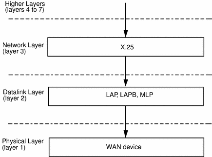
The component layers of X.25 fit together as shown in Figure 2-3:
Figure 2-3 X.25 Protocol Layers Overview

X.25 Physical Layer
As with any protocol stack, the physical layer specifies the mechanical, electrical, functional, and procedural characteristics that are necessary to activate, maintain, and terminate a physical connection between the DTE and DCE.
The ITU-T X.25 Recommendation does not itself specify how the physical layer should work. Instead, it refers to other ITU-T Recommendations, and specifies which of these may be used. The Recommendations specified are: X.21, X.21 bis, X.31 and the V-series interfaces, that is V11, V24 and V25bis.
Electronic Industries Association (EIA) specifications are often compatible with the V-series interfaces and can be used with X.25. The chart below lists equivalent standards.
Table 2-1 ITU-T V-series and Equivalent EIA Inferfaces|
ITU-T |
Equivalent EIA |
|---|---|
|
V24, V28 |
RS232, RS423 |
|
V11 |
RS449 |
X.25 Datalink Layer
The datalink layer's role is to specify the link access procedure for the exchange of data across the physical link. This layer must ensure that all data transmitted at one end of a link reaches the other end intact.
This means that as well as mechanisms for transmitting data, the datalink layer must provide ways of telling whether data has reached its destination correctly, and retransmitting if it has not.
The X.25 Recommendation defines two possible datalink layers: LAP and LAPB. In practice, LAP is rarely used. A Multilink Procedure (MLP) allows for multilink operations. It is used along with LAPB.
Single Link Operations
Figure 2-4 shows the standard frame structure for a bit-oriented datalink layer frame. The shaded parts are supplied by the datalink layer. The Data field contains the data supplied by higher layer protocols. Sizes are given in octets
Figure 2-4 Datalink Layer Frame Structure

Datalink layer frames are structured as follows:
- Flag
-
Frames are delimited at each end by a flag, with the value 01111110. This is necessary because X.25 is synchronous - in other words, data is transmitted as a continuous stream.
- Address
-
This is one octet. The value varies, depending on the direction of data flow, and on whether this is a single or multilink operation.
- Control
-
The control octet define the type of frame this is: an I(nformation)-frame containing data, a S(upervisory)-frame, which is a response frame, or an U(nnumbered)-frame, which performs control functions.
- Data
-
The data field contains X.25 protocol information, as well as user data from higher layer protocols. A frame need not contain data.
- Checksum
-
The two-octet checksum follows the data, and is derived from the contents of the data packet. It is usually generated automatically by the hardware.
Multilink Operations
Figure 2-5 Multilink Operation

The Multilink Protocol (MLP) lets you use more than one physical connection to make a single logical connection. This increases the amount of bandwidth available between the DTE and DCE improving response times and increasing traffic levels. An MLP connection does not provide a multiple channel end to end connection to remote DTEs. Not all of the DTEs attached to the PSDN need to use MLP and not all DTEs need to use the same number of physical connections.
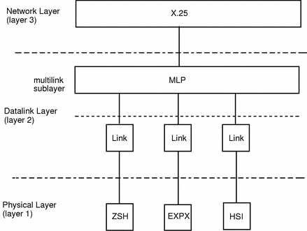
The internal structure of X.25 when using MLP is shown below:
Figure 2-6 Internal Structure of X.25 When Using MLP

MLP frames have two additional octets placed between the control octet and the data. These octets enable each frame to have a sequence number so that it can be reassembled in the correct order at the receiving end. The two extra octets are not present in the standard datalink frame shown in Figure 2-4.
X.25 Packet Layer
Within layer 3, the Packet Layer Protocol manages the exchange of data packets between DTE and DCE. This layer establishes, maintains, and terminates user sessions, handles addressing and carries out fault-management.
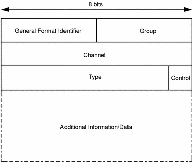
The general format of an X.25 packet header is shown below:
Figure 2-7 X.25 Packet Header Format

The components are:
- General Format Identifier
-
This specifies the format of the rest of the header, which varies according to packet-type.
- Group and Channel
-
Together, the Group and Channel fields identify the virtual circuit to be used for a call.
- Type
-
In a control (non-data) packet, the type field identifies the type of the packet. In a data packet, the type field is used for setting flow control, sequencing, and piggybacking information.
- Control
-
The Control field specifies whether this is a control or a data packet. It is set to 1 for control packets and 0 for data packets.
In data packets, the header is followed by data. In control packets, the header is followed by additional information that specifies, among other things, addressing and any special facilities that are to be used.
- © 2010, Oracle Corporation and/or its affiliates
