Building the Null Modem Cable
The following subsections provide four null-modem-cable schematic diagrams. The first pair of diagrams are RS-232-C null modems; the second pair are RS-449 null modems. Within each pair, one diagram illustrates a null modem cable to connect two Sun machines in which both Sun machines supply the clocking. The other diagram illustrates a null modem cable to connect a Sun machine to another Sun or non-Sun machine, in which only one Sun machine supplies clocking for both sides.
To build a null modem cable, you can configure your own cable or use a standard cable with an adapter box. If you decide to use an adapter box, be sure to obtain an adapter that allows you to change pin configurations. Pre-configured adapters generally do not work with synchronous protocols because they do not handle clock signals correctly.
For an RS-232-C cable, use a good quality, shielded wire. For an RS-449 cable, it is best to use shielded, twisted-pair wire.
RS-232-C Null Modem Cables
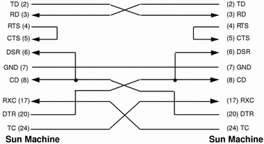
The following diagram illustrates a synchronous null modem that allows you to connect two Sun machines that each supply clocking, using the RS-232-C interface. Each Sun machine supplies clocking on pin 24. The null modem routes this clocking to pin 17 on the opposite side to provide receive clocking.
In x25tool Link Editor window, set the Tx Clock parameter to the bit rate you want (not External) on both machines.
Figure A-1 RS-232-C Null Modem: Both Sun Machines Supply Clocking
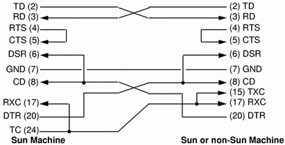
The following diagram illustrates a synchronous null modem that allows you to connect a Sun machine to another Sun or non-Sun machine, using the RS-232-C interface. The Sun machine supplies both the transmit and receive clocks for the other machine. Note that this null modem is not symmetrical.
In x25tool Link Editor, set the Tx Clock parameter to the bit rate you want (not External) on the Sun machine that is to supply clocking.
Figure A-2 RS-232-C Null Modem: Sun Machine Supplies Clocking for Both Sides
RS-449 Null Modem Cables
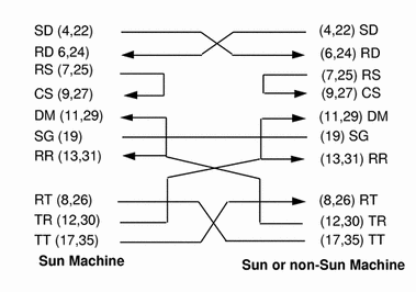
The following diagram illustrates a synchronous null modem cable that allows you to connect two Sun machines that each supply clocking, using the RS-449 interface. Each Sun machine supplies clocking on pins 17 and 35. The null modem cable routes this clocking to pins 8 and 26 on the opposite side to provide receive clocking.
Because the RS-449 interface is balanced, there are two pins for each signal. For example, in the diagram below, Send Data (SD), pins 4 and 22, is connected to Receive Data (RD), pins 6 and 24. This means that pin 4 is connected to pin 6 and pin 22 is connected to pin 24.
In x25tool Link Editor window, set the Tx Clock parameter to the bit rate you want (not External) on both machines.
Figure A-3 RS-449 Null Modem Cable: Both Machines Supply Clocking
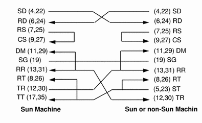
The following diagram illustrates a synchronous null modem cable that allows you to connect a Sun machine to another Sun or non-Sun machine, using the RS-449 interface. The Sun machine supplies both the transmit and receive clocks for the other machine. Note that this null modem cable is not symmetrical.
Because the RS-449 interface is balanced, there are two pins for each signal. For example, in the diagram below, Send Data (SD), pins 4 and 22, is connected to Receive Data (RD), pins 6 and 24. This means that pin 4 is connected to pin 6 and pin 22 is connected to pin 24.
In x25tool Link Editor, set the Tx Clock parameter to the bit rate you want (not External) on the Sun machine that is to supply clocking.
Figure A-4 RS-449 Null Modem Cable: Sun Machine Supplies Clocking
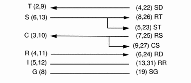
X.21-to-RS-449 Converter
Tables A-1 and A-2 list the signals and names for RS-449 and X.21 circuits.
Table A-1 RS-449 Signals|
Circuit |
Name |
Direction |
|---|---|---|
|
SD |
Send Data |
To DCE |
|
RD |
Receive Data |
From DCE |
|
TT |
Terminal Timing |
To DCE |
|
ST |
Send Timing |
From DCE |
|
RT |
Receive Timing |
From DCE |
|
RS |
Request to Send |
To DCE |
|
CS |
Clear to Send |
From DCE |
|
RR |
Receiver Ready |
From DCE |
|
TR |
Terminal Ready |
To DCE |
|
DM |
Data Mode |
From DCE |
|
SG |
Signal Ground |
|
Table A-2 X.21 Signals
|
Circuit |
Name |
Direction |
|---|---|---|
|
G |
Signal Ground |
|
|
T |
Transmit |
To DCE |
|
R |
Receive |
From DCE |
|
C |
Control |
To DCE |
|
I |
Indication |
From DCE |
|
S |
Signal Element Timing |
From DCE |
|
B |
Byte Timing |
From DCE |
The diagram below illustrates the pin connections required for an X.21-to-RS-449 converter.
Figure A-5 X.21-to-RS-449 Converter
- © 2010, Oracle Corporation and/or its affiliates
