Chapter 5 Administering VLANs
This chapter describes procedures to configure and maintain virtual local area networks (VLANs). The procedures include steps that avail of features such as support for flexible link names.
Administering Virtual Local Area Networks
A virtual local area network (VLAN) is a subdivision of a local area network at the data link layer of the TCP/IP protocol stack. You can create VLANs for local area networks that use switch technology. By assigning groups of users to VLANs, you can improve network administration and security for the entire local network. You can also assign interfaces on the same system to different VLANs.
Consider dividing your local network into VLANs if you need to do the following:
-
Create a logical division of workgroups.
For example, suppose all hosts on a floor of a building are connected on one switched-based local network. You could create a separate VLAN for each workgroup on the floor.
-
Enforce differing security policies for the workgroups.
For example, the security needs of a Finance department and an Information Technologies department are quite different. If systems for both departments share the same local network, you could create a separate VLAN for each department. Then, you could enforce the appropriate security policy on a per-VLAN basis.
-
Split workgroups into manageable broadcast domains.
The use of VLANs reduces the size of broadcast domains and improves network efficiency.
Overview of VLAN Topology
Switched LAN technology enables you to organize the systems on a local network into VLANs. Before you can divide a local network into VLANs, you must obtain switches that support VLAN technology. You can configure all ports on a switch to serve a single VLAN or multiple VLANs, depending on the VLAN topology design. Each switch manufacturer has different procedures for configuring the ports of a switch.
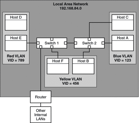
The following figure shows a local area network that has the subnet address 192.168.84.0. This LAN is subdivided into three VLANs, Red, Yellow, and Blue.
Figure 5–1 Local Area Network With Three VLANs

Connectivity on LAN 192.168.84.0 is handled by Switches 1 and 2. The Red VLAN contains systems in the Accounting workgroup. The Human Resources workgroup's systems are on the Yellow VLAN. Systems of the Information Technologies workgroup are assigned to the Blue VLAN.
VLAN Tags and Physical Points of Attachment
Each VLAN in a local area network is identified by a VLAN tag, or VLAN ID (VID). The VID is assigned during VLAN configuration. The VID is a 12-bit identifier between 1 and 4094 that provides a unique identity for each VLAN. In Figure 5–1, the Red VLAN has the VID 789, the Yellow VLAN has the VID 456, and the Blue VLAN has the VID 123.
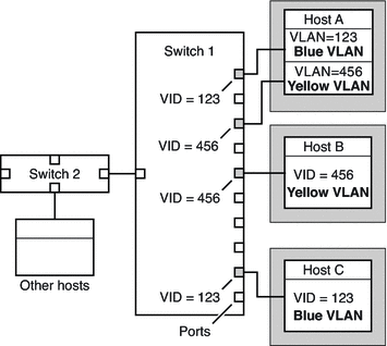
When you configure switches to support VLANs, you need to assign a VID to each port. The VID on the port must be the same as the VID assigned to the interface that connects to the port, as shown in the following figure.
Figure 5–2 Switch Configuration for a Network with VLANs

Figure 5–2 shows multiple hosts that are connected to different VLANs. Two hosts belong to the same VLAN. In this figure, the primary network interfaces of the three hosts connect to Switch 1. Host A is a member of the Blue VLAN. Therefore, Host A's interface is configured with the VID 123. This interface connects to Port 1 on Switch 1, which is then configured with the VID 123. Host B is a member of the Yellow VLAN with the VID 456. Host B's interface connects to Port 5 on Switch 1, which is configured with the VID 456. Finally, Host C's interface connects to Port 9 on Switch 1. The Blue VLAN is configured with the VID 123.
The figure also shows that a single host can also belong to more than one VLAN. For example, Host A has two interfaces. The second interface is configured with the VID 456 and is connected to Port 3 which is also configured with the VID 456. Thus, Host A is a member of both the Blue VLAN and the Yellow VLAN.
Meaningful Names for VLANs
In this Solaris release, you can assign meaningful names to VLAN interfaces. VLAN names consist of a link name and the VLAN ID number (VID), such as sales0 You should assign customized names when you create VLANs. For more information about customized names, see Assigning Names to Data Links. For more information about valid customized names, see Rules for Valid Link Names.
Planning for VLANs on a Network
Use the following procedure to plan for VLANs on your network.
 How to Plan a VLAN Configuration
-
Examine the local network topology and determine where subdivision into VLANs is appropriate.
For a basic example of such a topology, refer to Figure 5–1.
-
Create a numbering scheme for the VIDs, and assign a VID to each VLAN.
Note –A VLAN numbering scheme might already exist on the network. If so, you must create VIDs within the existing VLAN numbering scheme.
-
On each system, determine which interfaces will be members of a particular VLAN.
-
Check the connections of the interfaces to the network's switches.
Note the VID of each interface and the switch port where each interface is connected.
-
Configure each port of the switch with the same VID as the interface to which it is connected.
Refer to the switch manufacturer's documentation for configuration instructions.
Configuring VLANs
The following procedure shows how to create and configure a VLAN. In this Solaris release, all Ethernet devices can support VLANs. However, some restrictions exist with certain devices. For these exceptions, refer to VLANs on Legacy Devices.
 How to Configure a VLAN
Before You Begin
Data links must already be configured on your system before you can create VLANs. See How to Configure an IP Interface After System Installation.
-
On the system in which you configure VLANs, assume the Primary Administrator role, or become superuser.
The Primary Administrator role includes the Primary Administrator profile. To create the role and assign the role to a user, see Chapter 2, Working With the Solaris Management Console (Tasks), in System Administration Guide: Basic Administration.
-
Determine the types of links that are in use in your system.
# dladm show-link
-
Create a VLAN link over a data-link.
# dladm create-vlan -l link -v VID vlan-link
- link
-
Specifies the link on which the VLAN interface is being created.
- VID
-
Indicates the VLAN ID number
- vlan-link
-
Specifies the name of the VLAN, which can also be an administratively-chosen name.
-
Verify the VLAN configuration.
# dladm show-vlan
-
Configure an IP interface over the VLAN.
# ifconfig interface plumb IP-address up
where interface takes the same name as the VLAN name.
Note –You can assign IPv4 or IPv6 addresses to the VLAN's IP interface.
-
(Optional) To make the IP configuration for the VLAN persist across reboots, create an /etc/hostname.interface file to contain the interface's IP address.
The interface takes the name that you assign to the VLAN.
Example 5–1 Configuring a VLAN
This example configures the VLAN sales over the link subitops0. The VLAN is configured to persist across reboots.
# dladm show-link LINK CLASS MTU STATE OVER subitops0 phys 1500 up -- ce1 phys 1500 up -- # dladm create-vlan -l subitops0 -v 7 sales # dladm show-vlan LINK VID OVER FLAGS sales 7 subitops0 ---- |
When link information is displayed, the VLAN link is included in the list.
# dladm show-link LINK CLASS MTU STATE OVER subitops0 phys 1500 up -- ce1 phys 1500 up -- sales vlan 1500 up subitops0 # ifconfig sales plumb 10.0.0.3/24 up # echo 10.0.0.3/24 > /etc/hostname.sales |
VLANs on Legacy Devices
Certain legacy devices handle only packets whose maximum frame size is 1514 bytes. Packets whose frame sizes exceed the maximum limit are dropped. For such cases, follow the same procedure listed in How to Configure a VLAN. However, when creating the VLAN, use the -f option to force the creation of the VLAN.
The general steps to perform are as follows:
-
Create the VLAN with the -f option.
# dladm create-vlan -f -l link -v VID [vlan-link]
-
Set a lower size for the maximum transmission unit (MTU), such as 1496 bytes.
# dladm set-linkprop -p default_mtu=1496 vlan-link
The lower MTU value allows space for the link layer to insert the VLAN header prior to transmission.
-
Perform the same step to set the same lower value for the MTU size of each node in the VLAN.
For more information about changing link property values, refer to Administering NIC Driver Properties.
Performing Other Administrative Tasks on VLANs
This section describes the usage of new dladm subcommands for other VLAN tasks. These dladm commands also work with link names.
 How to Display VLAN Information
-
Assume the System Administrator role or become superuser.
The System Administrator role includes the Network Management profile. To create the role and assign the role to a user, see Chapter 9, Using Role-Based Access Control (Tasks), in System Administration Guide: Security Services.
-
Display VLAN information.
# dladm show-vlan [vlan-link]
If you do not specify a VLAN link, the command displays information about all configured VLANs.
Example 5–2 Displaying VLAN Information
The following example shows the available VLANs in a system.
# dladm show-vlan LINK VID OVER FLAGS sales 7 subitops0 ---- managers 5 net0 ---- |
Configured VLANs also appear when you issue the dladm show-link command. In the command output, the VLANs are appropriately identified in the CLASS column.
# dladm show-link LINK CLASS MTU STATE OVER subitops0 phys 1500 up -- sales vlan 1500 up subitops0 net0 phys 1500 up -- managers vlan 1500 up net0 |
 How to Remove a VLAN
-
Assume the System Administrator role or become superuser.
The System Administrator role includes the Network Management profile. To create the role and assign the role to a user, see Chapter 9, Using Role-Based Access Control (Tasks), in System Administration Guide: Security Services.
-
Determine which VLAN you want to remove.
# dladm show-vlan
-
Unplumb the VLAN's IP interface.
# ifconfig vlan-interface unplumb
where vlan-interface is the IP interface that is configured over the VLAN.
Note –You cannot remove a VLAN that is currently in use.
-
Remove the VLAN by performing one of the following steps:
Example 5–3 Removing a VLAN
# dladm show-vlan LINK VID OVER FLAGS sales 5 subitops0 ---- managers 7 net0 ---- # ifconfig managers unplumb # dladm delete-vlan managers # rm /etc/hostname.managers |
- © 2010, Oracle Corporation and/or its affiliates
