Deploying IPMP
This section describes various topics about the use of IPMP groups.
Why You Should Use IPMP
Different factors can cause an interface to become unusable. Commonly, an IP interface can fail. Or, an interface might be switched offline for hardware maintenance. In such cases, without an IPMP group, the system can no longer be contacted by using any of the IP addresses that are associated with that unusable interface. Additionally, existing connections that use those IP addresses are disrupted.
With IPMP, one or more IP interfaces can be configured into an IPMP group. The group functions like an IP interface with data addresses to send or receive network traffic. If an underlying interface in the group fails, the data addresses are redistributed among the remaining underlying active interfaces in the group. Thus, the group maintains network connectivity despite an interface failure. With IPMP, network connectivity is always available, provided that a minimum of one interface is usable for the group.
Additionally, IPMP improves overall network performance by automatically spreading out outbound network traffic across the set of interfaces in the IPMP group. This process is called outbound load spreading. The system also indirectly controls inbound load spreading by performing source address selection for packets whose IP source address was not specified by the application. However, if an application has explicitly chosen an IP source address, then the system does not vary that source address.
When You Must Use IPMP
The configuration of an IPMP group is determined by your system configurations. Observe the following rules:
-
Multiple IP interfaces on the same local area network or LAN must be configured into an IPMP group. LAN broadly refers to a variety of local network configurations including VLANs and both wired and wireless local networks whose nodes belong to the same link-layer broadcast domain.
-
Underlying IP interfaces of an IPMP group must not span different LANs.
For example, suppose that a system with three interfaces is connected to two separate LANs. Two IP interfaces link to one LAN while a single IP interface connects to the other. In this case, the two IP interfaces connecting to the first LAN must be configured as an IPMP group, as required by the first rule. In compliance with the second rule, the single IP interface that connects to the second LAN cannot become a member of that IPMP group. No IPMP configuration is required of the single IP interface. However, you can configure the single interface into an IPMP group to monitor the interface's availability. The single-interface IPMP configuration is discussed further in Types of IPMP Interface Configurations.
Consider another case where the link to the first LAN consists of three IP interfaces while the other link consists of two interfaces. This setup requires the configuration of two IPMP groups: a three-interface group that links to the first LAN, and a two-interface group to connect to the second.
Comparing IPMP and Link Aggregation
IPMP and link aggregation are different technologies to achieve improved network performance as well as maintain network availability. In general, you deploy link aggregation to obtain better network performance, while you use IPMP to ensure high availability.
The following table presents a general comparison between link aggregation and IPMP.
|
IPMP |
Link Aggregation |
|
|---|---|---|
|
Network technology type |
Layer 3 (IP layer) |
Layer 2 (link layer) |
|
Configuration tool |
ifconfig |
dladm |
|
Link-based failure detection |
Supported. |
Supported. |
|
Probe-based failure detection |
ICMP-based, targeting any defined system in the same IP subnet as test addresses, across multiple levels of intervening layer-2 switches. |
Based on Link Aggregation Control Protocol (LACP), targeting immediate peer host or switch. |
|
Use of standby interfaces |
Supported |
Not supported |
|
Span multiple switches |
Supported |
Generally not supported; some vendors provide proprietary and non-interoperable solutions to span multiple switches. |
|
Hardware support |
Not required |
Required. For example, a link aggregation in the system that is running the Solaris OS requires that corresponding ports on the switches be also aggregated. |
|
Link layer requirements |
Broadcast-capable |
Ethernet-specific |
|
Driver framework requirements |
None |
Must use GLDv3 framework |
|
Load spreading support |
Present, controlled by kernel. Inbound load spreading is indirectly affected by source address selection. |
Finer grain control of the administrator over load spreading of outbound traffic by using dladm command. Inbound load spreading supported. |
In link aggregations, incoming traffic is spread over the multiple links that comprise the aggregation. Thus, networking performance is enhanced as more NICs are installed to add links to the aggregation. IPMP's traffic uses the IPMP interface's data addresses as they are bound to the available active interfaces. Thus, for example, if all the data traffic is flowing between only two IP addresses but not necessarily over the same connection, then adding more NICs will not improve performance with IPMP because only two IP addresses remain usable.
The two technologies complement each other and can be deployed together to provide the combined benefits of network performance and availability. For example, except where proprietary solutions are provided by certain vendors, link aggregations currently cannot span multiple switches. Thus, a switch becomes a single point of failure for a link aggregation between the switch and a host. If the switch fails, the link aggregation is likewise lost, and network performance declines. IPMP groups do not face this switch limitation. Thus, in the scenario of a LAN using multiple switches, link aggregations that connect to their respective switches can be combined into an IPMP group on the host. With this configuration, both enhanced network performance as well as high availability are obtained. If a switch fails, the data addresses of the link aggregation to that failed switch are redistributed among the remaining link aggregations in the group.
For other information about link aggregations, see Chapter 6, Administering Link Aggregations.
Using Flexible Link Names on IPMP Configuration
With support for customized link names, link configuration is no longer bound to the physical NIC to which the link is associated. Using customized link names allows you to have greater flexibility in administering IP interfaces. This flexibility extends to IPMP administration as well. In certain cases of failure of an underlying interface of an IPMP group, the resolution would require the replacement of the physical hardware or NIC. The replacement NIC, provided it is the same type as the failed NIC, can be renamed to inherit the configuration of the failed NIC. You do not have to create new configurations for the new NIC before you can add it to the IPMP group. After you rename the new NIC's link with the link name of the replaced NIC, the new NIC automatically becomes a member of the IPMP group when you bring that NIC online. The multipathing daemon then deploys the interface according to the IPMP configuration of active and standby interfaces.
Therefore, to optimize your networking configuration and facilitate IPMP administration, you must employ flexible link names for your interfaces by assigning them generic names. In the following section How IPMP Works, all the examples use flexible link names for the IPMP group and its underlying interfaces. For details about the processes behind NIC replacements in a networking environment that uses customized link names, refer to IPMP and Dynamic Reconfiguration. For an overview of the networking stack and the use of customized link names, refer to Overview of the Networking Stack.
How IPMP Works
IPMP maintains network availability by attempting to preserve the original number of active and standby interfaces when the group was created.
IPMP failure detection can be link-based or probe-based or both to determine the availability of a specific underlying IP interface in the group. If IPMP determines that an underlying interface has failed, then that interface is flagged as failed and is no longer usable. The data IP address that was associated with the failed interface is then redistributed to another functioning interface in the group. If available, a standby interface is also deployed to maintain the original number of active interfaces.
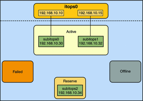
Consider a three-interface IPMP group itops0 with an active-standby configuration, as illustrated in Figure 7–1.
Figure 7–1 IPMP Active–Standby Configuration

The group itops0 is configured as follows:
-
Two data addresses are assigned to the group: 192.168.10.10 and 192.168.10.15.
-
Two underlying interfaces are configured as active interfaces and are assigned flexible link names: subitops0 and subitops1.
-
The group has one standby interface, also with a flexible link name: subitops2.
-
Probe–based failure detection is used, and thus the active and standby interfaces are configured with test addresses, as follows:
-
subitops0: 192.168.10.30
-
subitops1: 192.168.10.32
-
subitops2: 192.168.10.34
-
Note –
The Active, Offline, Reserve, and Failed areas in the figures indicate only the status of underlying interfaces, and not physical locations. No physical movement of interfaces or addresses nor transfer of IP interfaces occur within this IPMP implementation. The areas only serve to show how an underlying interface changes status as a result of either failure or repair.
You can use the ipmpstat command with different options to display specific types of information about existing IPMP groups. For additional examples, see Monitoring IPMP Information.
The IPMP configuration in Figure 7–1 can be displayed by using the following ipmpstat command:
# ipmpstat -g GROUP GROUPNAME STATE FDT INTERFACES itops0 itops0 ok 10.00s subitops1 subitops0 (subitops2) |
To display information about the group's underlying interfaces, you would type the following:
# ipmpstat -i INTERFACE ACTIVE GROUP FLAGS LINK PROBE STATE subitops0 yes itops0 ------- up ok ok subitops1 yes itops0 --mb--- up ok ok subitops2 no itops0 is----- up ok ok |
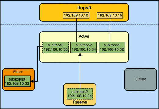
IPMP maintains network availability by managing the underlying interfaces to preserve the original number of active interfaces. Thus, if subitops0 fails, then subitops2 is deployed to ensure that the group continues to have two active interfaces. The activation of the subitops2 is shown in Figure 7–2.
Figure 7–2 Interface Failure in IPMP

Note –
The one–to–one mapping of data addresses to active interfaces in Figure 7–2 serves only to simplify the illustration. The IP kernel module can assign data addresses randomly without necessarily adhering to a one–to–one relationship between data addresses and interfaces.
The ipmpstat utility displays the information in Figure 7–2 as follows:
# ipmpstat -i INTERFACE ACTIVE GROUP FLAGS LINK PROBE STATE subitops0 no itops0 ------- up failed failed subitops1 yes itops0 --mb--- up ok ok subitops2 yes itops0 -s----- up ok ok |
After subitops0 is repaired, then it reverts to its status as an active interface. In turn, subitops2 is returned to its original standby status.
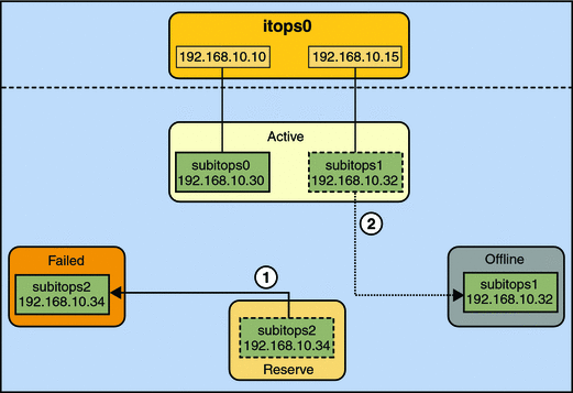
A different failure scenario is shown in Figure 7–3, where the standby interface subitops2 fails (1), and later, one active interface, subitops1, is switched offline by the administrator (2). The result is that the IPMP group is left with a single functioning interface, subitops0.
Figure 7–3 Standby Interface Failure in IPMP

The ipmpstat utility would display the information illustrated by Figure 7–3 as follows:
# ipmpstat -i INTERFACE ACTIVE GROUP FLAGS LINK PROBE STATE subitops0 yes itops0 ------- up ok ok subitops1 no itops0 --mb-d- up ok offline subitops2 no itops0 is----- up failed failed |
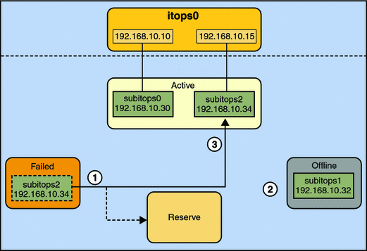
For this particular failure, the recovery after an interface is repaired behaves differently. The restoration depends on the IPMP group's original number of active interfaces compared with the configuration after the repair. The recovery process is represented graphically in Figure 7–4.
Figure 7–4 IPMP Recovery Process

In Figure 7–4, when subitops2 is repaired, it would normally revert to its original status as a standby interface (1). However, the IPMP group still would not reflect the original number of two active interfaces, because subitops1 continues to remain offline (2). Thus, IPMP deploys subitops2 as an active interface instead (3).
The ipmpstat utility would display the post-repair IPMP scenario as follows:
# ipmpstat -i INTERFACE ACTIVE GROUP FLAGS LINK PROBE STATE subitops0 yes itops0 ------- up ok ok subitops1 no itops0 --mb-d- up ok offline subitops2 yes itops0 -s----- up ok ok |
A similar restore sequence occurs if the failure involves an active interface that is also configured in FAILBACK=no mode, where a failed active interface does not automatically revert to active status upon repair. Suppose subitops0 in Figure 7–2 is configured in FAILBACK=no mode. In that mode, a repaired subitops0 is switched to a reserve status as a standby interface, even though it was originally an active interface. The interface subitops2 would remain active to maintain the IPMP group's original number of two active interfaces. The ipmpstat utility would display the recovery information as follows:
# ipmpstat -i INTERFACE ACTIVE GROUP FLAGS LINK PROBE STATE subitops0 no itops0 i------ up ok ok subitops1 yes itops0 --mb--- up ok ok subitops2 yes itops0 -s----- up ok ok |
For more information about this type of configuration, see The FAILBACK=no Mode.
- © 2010, Oracle Corporation and/or its affiliates
