Chapter 2 Sun N1 System Manager System and Network Preparation
This chapter provides the Sun N1 System Manager hardware and software requirements, reference architectures, and procedures for preparing your N1 System Manager components.
The tasks provided in this chapter can be performed in parallel with the management server preparation as described in Chapter 3, Installing and Configuring an OS on the Management Server and Chapter 1, Installing and Configuring the Sun N1 System Manager Software, in Sun N1 System Manager 1.1 Installation and Configuration Guide.
Note –
Do not run discovery or use the N1 System Manager system until all provisionable servers have been configured as described by the following sections.
This chapter discusses the following topics:
Sun N1 System Manager Hardware and OS Requirements
The information in this section will help you determine what operating system, hardware, and storage resources must be allocated or acquired to implement the N1 System Manager system.
This section discusses the following topics:
Management Server Requirements
N1 System Manager management server hardware and operating software minimum requirements are listed in the following table. See Table 2–3 for specific management server sizing information based on the number of provisionable servers to be managed.
Dedicate the management server only to N1 System Manager software. Do not install other applications on the management server.
Table 2–1 Management Server Hardware and Operating System Requirements
|
Type |
Operating System |
Disk Space |
RAM |
|
|---|---|---|---|---|
|
SPARC |
||||
|
NetraTM 240, 440 |
Solaris 10 |
72 Gbytes minimum |
4 Gbytes minimum |
|
|
Sun FireTM V210, V240, V440 |
Solaris 10 |
|||
|
x86 |
||||
|
Sun Fire X4100 and X4200 |
Solaris x86 Version 10 HW1 Red Hat Enterprise Linux 3.0 AS Update 5, 32–bit and 64–bit |
72 Gbytes minimum |
4 Gbytes minimum |
|
|
Sun Fire V20z and V40z |
Solaris x86 Version 10 Red Hat Enterprise Linux 3.0 AS Update 2 through 5, 32–bit and 64–bit |
|||
A minimum of 3.0 Gbytes should be allocated for each OS distribution you plan to provision.
-
On a Solaris-based management server, OS distributions are stored as follows:
-
Linux OS distributions are stored in /var/opt/SUNWscs/share/allstart
-
Solaris OS distributions are stored in /var/js
-
-
On a Linux-based management server, OS distributions are stored as follows:
-
Linux OS distributions are stored in /var/opt/sun/scs/share/allstart/
-
Solaris OS distributions are stored in /var/opt/sun/scs/share/allstart/jumpstart/
-
Note –
For ease of administration, install a 10/100 NIC as ETH2 in the N1 System Manager management server to provide connectivity through the management switch to the management interfaces of the provisionable servers. Example diagrams and configurations in this document assume that an additional 10/100/1000 NIC has been installed in the management server.
Provisionable Server Requirements
N1 System Manager provisionable server hardware and operating software requirements are listed in the following table.
Table 2–2 Provisionable Server Hardware and Operating System Requirements|
Server Type |
Provisionable OS |
Disk Space Requirements |
RAM Requirements |
|
|---|---|---|---|---|
|
SPARC |
||||
|
Sun Netra 240 and 440 |
Solaris 10 Solaris 9 7/05 |
12 Gbytes minimum |
512 Mbytes minimum, 1 Gbyte recommended |
|
|
Sun Fire V210, V240, and V440 |
Solaris 10 Solaris 9 7/05 |
12 Gbytes minimum |
512 Mbytes minimum, 1 Gbyte recommended |
|
|
x86 |
||||
|
Sun Fire X4100 and X4200 |
Solaris 10 HW1 Red Hat Enterprise Linux AS 4.0 Update 1, 64 bit only Red Hat Enterprise Linux ES 4.0 Update 1, 64 bit only Red Hat Enterprise Linux AS 3.0, Update 5, 32 bit and 64 bit Red Hat Enterprise Linux ES 3.0, Update 5, 32 bit and 64 bit SUSE Linux Enterprise Server 9 SP1, 64 bit only |
12 Gbytes minimum |
512 Mbytes minimum, 1 Gbyte recommended |
|
|
Sun Fire V20z and V40z |
Solaris x86 Version 10 Solaris x86 Version 9 Update 7 Red Hat Enterprise Linux AS 4.0, 32 bit and 64 bit Red Hat Enterprise Linux ES 4.0, 32 bit and 64 bit Red Hat Enterprise Linux AS 3.0, Updates 1 through 5, 32 and 64 bit Red Hat Enterprise Linux ES 3.0, Updates 1 through 5, 32 and 64 bit SUSE Linux Enterprise Server 9 and SP1, 32 and 64 bit |
12 Gbytes minimum |
512 Mbytes minimum, 1 Gbyte recommended |
|
Recommended Switch Configuration
You can use a single VLAN-programmable switch to provide the management, provisioning, and data network infrastructure. However, for ease of management, you should install one VLAN-programmable switch for the management network, and a second VLAN-programmable switch for the provisioning and data network. Each management, provisioning, and data network should be assigned to separate subnets and VLANs.
Note –
The management network switch must be configured to auto-negotiate link speed. If link speed is not auto-negotiated, firmware updates to Sun Fire V20z and V40z servers can fail.
The management switch and the provisioning and data network switch should support the following Ethernet connectivity.
-
-
10/100 megabit per second connectivity from the management server to the management switch to provide connectivity to each provisionable servers management port
-
10/100 megabit per second connectivity from each provisionable server management port to the management switch
The management network should be on a private subnet, and must provide connectivity to a management port on each provisionable server
-
-
Provisioning and Data Network Switch
-
1 gigabit per second connectivity from the management server ETH1 port to the provisioning and data switch
-
1 gigabit per second connectivity from each provisionable server ETH0 port to the provisioning and data switch
-
1 gigabit per second connectivity from each provisionable server ETH1 port to the provisioning and data switch
-
1 gigabit per second connectivity from the provisioning and data switch to the corporate network
The provisioning network should be on a private subnet.
Note –OS provisioning of Linux might fail if there is a delay in the transmission of data between the management server and the provisionable server is too long. A long delay can result if the spanning tree option is enabled for the switch port connected to the ETH0 port of the provisionable server. To address this issue, you can disable the spanning tree option for the switch or for the switch ports connected to the provisionable servers. Refer to your switch documentation for instructions about how to disable spanning tree on your switch.
Note –The data network should be on a public subnet accessible by the management server, provisionable servers, and the corporate network.
Due to the use of the DHCP protocol and the bandwidth requirements for OS provisioning, isolating the data network from the provisioning network might be required.
-
Sun N1 System Manager Connection Information
This section provides the connectivity requirements for the Sun N1 System Manager servers.
The following topics are discussed:
Management Server Connections
This section provides the logical port diagram and connectivity requirements for the Sun N1 System Manager management server.
A SPARC or x86 based server can be used as the management server as described by Table 2–1. Each server provides at least one 10/100/1000 (1 Gbit) network interface port, but adding additional Gbit network interface cards to the management server increases ease of management and physical separation of the corporate and provisioning networks. If you do not additional NICs, you can configure your network to route the corporate and provisioning networks through a single 1 Gbit port. This document assumes that your management server has three Gbit NICs.
Each server also provides one or two system management ports depending on server architecture, labeled Net Mgmt (Network Management), ALOM (Advanced Lights Out Manager port), or ILOM (Integrated Lights Out Manager port) on single management port servers, and labeled SP0 and SP1 (Service Processor 1 and 2) on dual management port servers. The management server requires only a single management port to provide connectivity with the corporate network. In this document, the management port is always shown as MGMT.
Note –
Depending on the system architecture and the operating system installed, the operating system refers to the Ethernet ports by different names. For example, the first Ethernet port on a machine is referred to as ETH0, HME0, or BGE0 depending on the operating system. This document refers to the lowest order Ethernet port on a machine as ETH0, the next port as ETH1 and so on regardless of architecture and operating system.
The following illustration provides the logical diagram of the management server ports, and is used in subsequent sections to illustrate reference architecture and production VLAN diagrams.
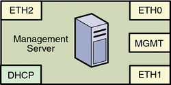
|
The management server should provide connectivity to three separate networks using the ports as follows:
-
The management port connects the management server to the corporate network. The management port connection provides external power up and power down access to the management server, enables firmware updates from the corporate network, and enables you to check the status of the management server from the corporate network. The management port is a 100–Mbit NIC interface.
-
ETH0 connects the management server to the corporate network to provide external access to the management server. The management server ETH0 IP address, netmask, and gateway should be configured to meet your corporate environment connectivity requirements. DNS configuration is performed during the N1 System Manager configuration process. ETH0 should be a 1 Gbit NIC interface.
-
ETH1 connects the management server to the provisioning network and should be on the same switch and network as the ETH0 connections of the provisionable servers. The management server ETH1 IP address, netmask, and gateway can be configured to support hundreds of provisionable servers. No devices other than the management server and the provisionable servers should reside on the provisioning network. ETH1 should be a 1 Gbit NIC interface.
-
ETH2 connects the management server to the management network and should be on the same switch and network as the management port connections of the provisionable servers. The management server connection is not required to be on the same switch as the management port connections of the provisionable servers as long as connectivity to the provisionable servers management port is provided. The management server ETH2 IP address, netmask, and gateway should be configured to enable connectivity to the provisionable servers management port IP addresses. ETH2 should be a 1 Gbit NIC interface.
-
The management server DCHP service allocates IP addresses to the provisionable servers for loading operating systems and updates over the provisioning network, and for runtime monitoring of the provisionable server operating environment.
Note –The management server DCHP service does not provide DHCP services for the data network. If you plan to dynamically configure IP services on the data network, you must provide an external DHCP server for the data network. You must not have another DHCP server on the same provisioning network.
Provisionable Server Connections
This section provides the logical port diagrams and connectivity requirements for the Sun N1 System Manager provisionable server.
A SPARC or x86–based server can be used as a provisionable server as described by Management Server Requirements. Each server provides two 10/100/1000 network interface ports. Each server also provides one or two system management ports depending on server architecture, labeled ALOM or ILOM on single management port servers, and labeled SP0 and SP1 on dual management port servers. In this document, the management port is always shown as MGMT.
The following illustrations provide the logical diagrams for the provisionable server ports based on the server architecture, and are used in subsequent sections to illustrate reference diagrams.
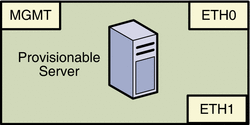
|
Each provisionable server should provide connectivity to three separate networks as follows:
-
The management port connects the provisionable server to the management network and should be on the same switch and network as the ETH2 connection of the management server. The provisionable server management port connection is not required to be on the same switch as the ETH2 connection of the management server as long as connectivity to the management server ETH2 port is provided.
The management port should be a 100 megabit connection.
-
ETH0 connects the provisionable server to the provisioning network and must be on the same switch and network as the ETH1 connection of the management server.
ETH0 should be a 1 Gbyte connection.
-
ETH1 connects the provisionable server to the data network through the switch to provide external corporate network access to the provisionable server.
ETH1 should be a 1 Gbyte connection.
The next section provides reference system connection and VLAN configurations for the N1 System Manager.
Reference Configurations
This section provides reference configurations that will assist you in designing and connecting your N1 System Manager equipment. The following topics are discussed:
-
Combined Management and Provisioning Network, and a Separate Data Network
-
Combined Provisioning and Data Network, and a Separate Management Network
Note –
In each of the following reference configurations, corporate access is shown as a connection to the management server. Alternatively, corporate access to the N1 System Manager can be provided through a switch instead of the management server.
Other configurations are possible, such as using separate switches for each network. You can implement your network using any combination of VLANs and switches. Each network, whether management, provisioning or data, should be assigned to separate VLANs.
Separate Management, Provisioning, and Data Networks
Figure 2–1 Separate Management, Provisioning, and Data Networks
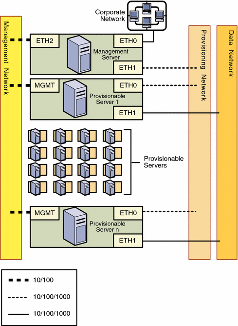
Notes:
-
Configuring separate management, provisioning, and data networks is the best practice
-
Separate networks provide the highest security and the lowest number of points of failure
-
The corporate DHCP service can be used to assign IP addresses to provisioned servers
-
You might need to install additional NICs in the management server and some provisionable servers to support this configuration
Combined Management and Provisioning Network, and a Separate Data Network
Figure 2–2 Combined Management and Provisioning Networks, and a Separate Data Network
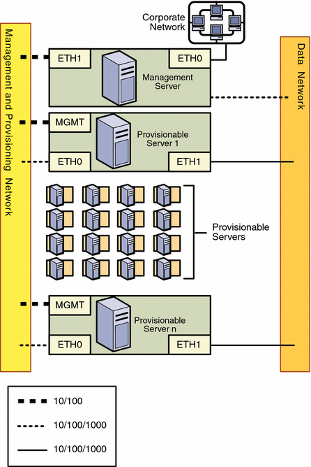
Notes:
-
An additional NIC does not need to be installed on the management server
-
The combined management and provisioning network reduces system and network security
-
The corporate DHCP service can be used to assign IP addresses to provisioned servers
The statically-assigned management IP addresses and the dynamically assigned IP addresses used during OS provisioning are part of the same network. The N1 System Manager does not manage IP addresses. You must ensure that the IP addresses used during provisioning do not conflict with the management network IP addresses.
Combined Provisioning and Data Network, and a Separate Management Network
Figure 2–3 Combined Provisioning and Data Network, and a Separate Management Network

Notes:
-
An additional NIC does not need to be installed on the management server
-
The combined provisioning and data network reduces system and network security
-
The data network must use the N1 System Manager DHCP service
The statically-assigned management IP addresses and the dynamically assigned IP addresses used during OS provisioning are part of the same network. The N1 System Manager does not manage IP addresses. You must ensure that the IP addresses used during provisioning do not conflict with the management network IP addresses.
Combined Provisioning, Data, and Management Network
Figure 2–4 Combined Provisioning and Data Network, and a Separate Management Network
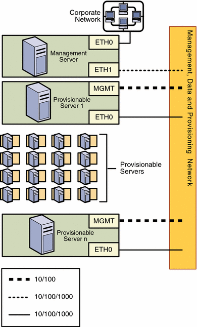
Notes:
-
An additional NIC does not need to be installed on the management server
-
The combined management, provisioning, and data networks greatly reduces system and network security
-
The data network must use the N1 System Manager DHCP service
The statically-assigned management IP addresses and the dynamically assigned IP addresses used during and after OS provisioning are part of the same network. The N1 System Manager does not manage IP addresses. You must ensure that the IP addresses used during provisioning and after provisioning do not conflict with the management network IP addresses.
Site Planning
This section provides guidelines for determining your management server and switch needs. The following topics are discussed:
Management Server Considerations
Hard drive capacity and the number of provisionable servers to be managed are the primary considerations for your management server.
-
Hard drive capacity is affected by two factors: the number of OS distributions that are to be provisioned, and the log files generated by each N1 System Manager job. OS distributions are stored in the /var/opt directory on the management server. Allocate 3 Gbytes for each OS distribution and its associated profiles and scripts.
Sufficient disk space should also be allocated for the N1 System Manager monitoring log files, which are stored in the N1 System Manager data base. Log file size depends on how you set up monitoring and the amount of detail chosen for each log. The n1smconfig utility is used to configure logging during initial N1 System Manager configuration, and can subsequently be used after the system is in production to reconfigure logging. For further information, see Chapter 5, Monitoring Your Servers, in Sun N1 System Manager 1.1 Administration Guide.
-
System processing is affected by three major factors: The number of provisionable servers being managed, the types of monitoring being performed on the provisionable servers, and the number of OS provisioning tasks running on the management server.
The following table provides sizing guidelines for the management server.
Table 2–3 Management Server Hardware Sizing Guidelines|
Small scale deployment: 1 to 256 provisionable servers |
||
|
Total number of processors |
1 or more single core AMD Opterons 1 or more 1x1 Ghz Ultra SPARC IIIi minimum |
|
|
Total memory |
4 Gbytes minimum |
|
|
Total file system space |
73 Gbytes minimum |
|
|
Media |
1 DVD ROM drive |
|
|
Qualified Sun Fire Models |
V20z, V40z, X4100, X4200, V210, V240, V280 and V440 |
|
|
Sample Configuration |
Sun Fire V20z Single Processor (single core) Opteron, 4 GB RAM, 1x73 GB HDD, DVD ROM Drive |
|
|
Medium scale deployment: 257 to 768 provisionable servers |
||
|
Total number of processors |
2 or more single core AMD Opterons, or 1 or more dual-core AMD Opterons 2 or more 1x1 Ghz Ultra SPARC IIIi minimum |
|
|
Total memory |
8 Gbytes minimum |
|
|
Total file system space |
146 Gbytes minimum |
|
|
Media |
1 DVD ROM drive |
|
|
Qualified Sun Fire Models |
V20z, V40z, X4100, X4200, V210, V240, V280 and V440 |
|
|
Sample Configuration |
Sun Fire V40z Dual Processor (dual core), 8 GB RAM, 1x146 GB HDD, DVD ROM Drive |
|
|
Large scale deployment: 769 to 1,024 provisionable servers |
||
|
Total number of processors |
4 single-core AMD Opterons, or 2 or more dual-core AMD Opterons 4 1x1 Ghz Ultra SPARC IIIi minimum |
|
|
Total memory |
16 Gbytes minimum |
|
|
Total file system space |
300 Gbytes minimum |
|
|
Media |
1 DVD ROM drive |
|
|
Qualified Sun Fire Models |
V20z, V40z, X4100, X4200, V440 |
|
|
Sample Configuration |
Sun Fire V40z Dual Processor (dual core), 16 GB RAM, 1x300 GB HDD, DVD ROM Drive |
|
Switch Considerations
Switch requirements are determined by the following factors:
-
Whether you have added a third 1–Gbit NIC to the management server
-
The number of management ports on each provisionable server
The number of provisionable servers to be connected to the switch
The V20z and V40z servers have two management ports, and subsequently can be daisy-chained. For further information, see Appendix A, Alternate Sun Fire V20z and V40z Reference Configuration.
-
The network topology you have chosen
The following worksheet will assist you in determining the total number of switch ports by type that you will need on your switch or switches.
Table 2–4 Switch Port Requirements Worksheet
Use the above totals to determine your switch requirements, and then connect the servers and switches according to your site plan.
Setting Up Provisionable Servers
Before you can use the N1 System Manager to discover provisionable servers, each provisionable server must be set up as follows:
-
An IP address must be assigned to the provisionable server's management port
-
The management processor credentials must be configured:
-
A Secure Shell (SSH) account must be created, and a password assigned to the account
-
The management processor Intelligent Platform Management Interface (IPMI) account must be configured and enabled where applicable
Discovery will fail if any of the above conditions are not met.
Tip –Install the operating system and the N1 System Manager software on your management server while you set up the provisionable servers.
-
Refer to your provisionable server documentation for procedures for assigning a management port IP address and for configuring the management processor credentials. You can also locate the server documentation at http://sunsolve.sun.com/handbook_pub/Systems/.
If you do not specify the Secure Shell (SSH) and Intelligent Platform Management Interface (IPMI) accounts and passwords, the discovery process assumes that the following credentials are configured on the provisionable servers:
-
Sun Fire X4100 and X4200 servers
-
SSH user = root
-
SSH password = changeme
-
IMPI user = root
-
IMPI password = changeme
-
-
Sun Fire V20z and V40z servers
-
SSH login = admin
-
SSH password = admin
-
IMPI login = Null
-
IMPI password= admin
-
SNMP read community string = public
-
-
Sun Fire V210, V240, V440 servers
-
Telnet login = admin
-
Telnet password = admin
-
Note –
Automatic configuration of credentials is supported for Sun Fire V20z and V40z servers if they are in the factory default state.
If you do specify the login accounts and passwords for discovery, the discovery process configures the provisionable server using the user-specified credentials. If only one credential is specified, the missing credential is configured with one of the defaults specified above.
- © 2010, Oracle Corporation and/or its affiliates
