Chapter 1 Sun N1 System Manager Overview
This chapter provides a summary of Sun N1 System Manager 1.0 functions and components.
Sun N1 System Manager Features
The Sun N1 System Manager is a system management tool that enables you to manage racks or other groupings of horizontally scaled servers using a single browser user interface. The Sun N1 System Manager browser interface provides an integrated command-line interface (CLI). A separate CLI is provided as well.
The Sun N1 System Manager system or N1 System Manager enables you to do the following tasks:
-
Discover servers on the network that can be provisioned by the N1 System Manager
-
Manage provisionable servers
-
Provision operating system and application software to the provisionable servers
-
Manage provisionable server firmware and patches
-
Monitor provisionable server health
-
Automate provisionable server configuration, recovery, and replacement
-
Maximize server utilization
-
Minimize user-visible hardware downtime
-
Log N1 System Manager and provisionable server events
Sun N1 System Manager Components
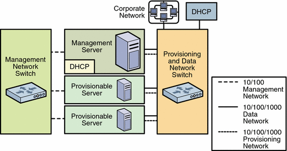
The following figure provides a high-level overview of the hardware components of the N1 System Manager.
Figure 1–1 N1 System Manager Components

The following list describes each of the components.
-
Management server and provisionable servers
-
The management server is the Solaris or Linux based server on which the N1 System Manager software is installed and run.
The management server DHCP service allocates IP addresses to the provisionable servers for loading operating systems and updates over the provisioning network, and for runtime monitoring of the provisionable server operating environment.
-
A provisionable server is one that has been successfully discovered by the N1 System Manager. Up to 32 provisionable servers can be installed in a single rack, and hundreds of provisionable servers can be managed by the N1 System Manager.
The management server and the provisionable servers can be any of the following machine types:
SPARC architecture: Sun NetraTM 240, and Sun FireTM V210, V240, and V440 servers
x86 architecture: Sun Fire X4100 and X4200, and Sun Fire V20z and V40z servers
-
-
The Corporate Network connection to the management server provides access to the data network and thus to the provisioned servers from the corporate network.
An Ethernet connection of 100 megabits per second is the minimum requirement. A 1,000 megabits (1 Gbit) connection is advised.
-
The Management Network provides the path to and from the management server and the provisionable servers management processor port. The management server uses the management network for server discovery, provisionable server firmware updates, and for provisionable server hardware management and monitoring.
The management network should be a private network that is accessible by the management server, and not accessible by the data network. An Ethernet connection of 100 megabits per second is the required minimum.
-
The management switch provides connectivity to a management port on each provisionable server, and should be a VLAN- programmable switch
-
The data and provisioning switch provides provisioning network and data network connectivity to and from the management server and the provisionable servers. The provisioning and data switch should be a VLAN- programmable switch
Ethernet connections of 1 Gbit per second are the required minimum.
The provisioning network requirements are as follows.
-
The provisioning network is used by the management server to configure and provision the operating and application environments on the provisionable servers, to monitor provisionable server OS resources, and to apply OS updates to provisionable servers.
Due to the use of the DHCP protocol and the bandwidth requirements for OS provisioning, isolating the provisioning network from the data network might be required.
-
The data network provides the connections from the provisionable servers to the corporate network through the management server for the end user. The corporate DHCP service allocates IP addresses to the provisionable servers to provide end user access to the provisionable server.
The data network should not have access to any of the N1 System Manager networks.
-
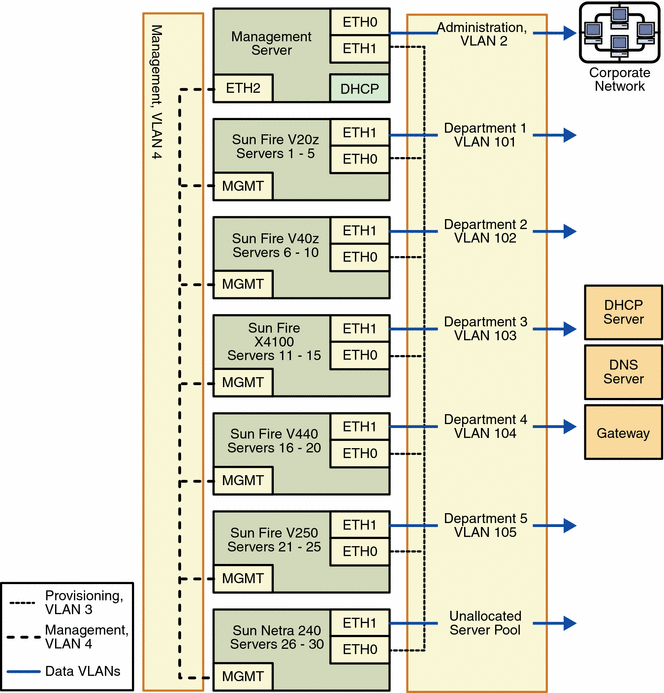
The following diagram illustrates a sample production environment in which the data and provisioning network are on separate VLANs, and in which multiple VLAN assignments have been used to configure the data network for end user access.

- © 2010, Oracle Corporation and/or its affiliates
