System Cabinet Fan Tray Assembly
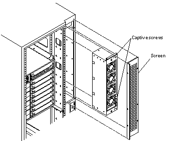
You must remove the fan tray screen (Figure E-1) to reach the assembly.
Note -
There is also a fan tray in the card cage ("Fan Tray Assembly, 200/240V") and one fan in the media tray.
Removing the Fan Tray Screen
Figure E-1 Replacing the Fan Tray Assembly in the Enterprise 6500/5500 Systems

-
Loosen the four screws on the left and the four screws on the right of the fan tray screen.
It is not necessary to completely remove these four screws.
-
Lift the screen up until the slotted screw holes clear the screw heads, and set it aside.
Removing the Fan Tray Assembly
-
Disconnect the power cable and fan cable assembly.
-
Loosen the two captive screws on the fan tray assembly (Figure E-1).
-
Tilt the fan tray assembly back slightly so that it clears the top of the cabinet.
-
Remove the fan tray assembly.
Replacing the Fan Tray Assembly
-
Tilt the fan tray assembly inward and lower it behind the upper sequencer bracket.
-
Push the fan tray into the cabinet until the fan tray cannot be inserted any further.
-
Tighten the two captive screws at the top and bottom of the fan tray (Figure E-1).
-
Replace the power cable and fan fail cable.
Replacing the Fan Tray Screen
- © 2010, Oracle Corporation and/or its affiliates
