Chapter 1 Product Overview
Standard Features
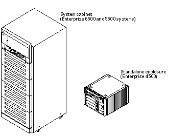
The Sun(TM) Enterprise(TM) 6500/5500/4500 systems are available in three styles of enclosures. This manual has specific details for two styles used for the Sun Enterprise 6500, 5500, and 4500 servers (Figure 1-1).
Many boards and modules are used in all three enclosures, including the CPU/Memory+ board, various types of I/O+ boards, the Disk board, processor modules, memory modules, most power supplies, and the CD-ROM drive.
Figure 1-1 Front Views of the Sun Enterprise 6500/5500 and 4500 Servers

Enterprise 6500 and 5500 Systems
The minimum configuration for the Enterprise 6500/5500 systems is:
-
Data center system cabinet (system cabinet)
-
16-slot (6500) or 8-slot (5500) card cage
-
Power/cooling modules (2)
-
Quad fan tray
-
Clock+ board
-
CPU/Memory+ board
-
UltraSPARC(TM) II module
-
Main memory
-
I/O+ board
-
Peripheral power supply
-
AC power sequencer
-
Media tray for removable SCSI media drives, such as the SunCD(TM) drive
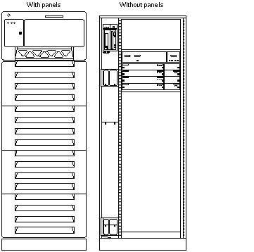
Figure 1-2 shows the front view of the Enterprise 5500 system. The Enterprise 6500 system is similar, but has a larger card cage (with eight boards in the front, eight boards in the rear).
Figure 1-2 Front View of the Enterprise 6500 System Cabinet

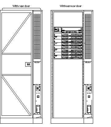
Figure 1-3 shows the rear view of the Enterprise 6500 system. Again, the Enterprise 5500 system is similar.
Figure 1-3 Rear View of the Enterprise 6500 System Cabinet

The top front panel varies with the number and type of options in the upper part of the Enterprise 6500/5500 system. Figure 1-4 shows two types of panels.
Figure 1-4 Bezels for Enterprise 6500/5500 System - Two Examples

Enterprise 4500 System
The minimum configuration for the Enterprise 4500 system is:
-
8-slot card cage
-
Power/cooling modules (2)
-
Fan box
-
Clock+ board
-
CPU/Memory+ board
-
UltraSPARC II module
-
Main memory
-
SBus+ I/O board
-
Peripheral power supply
-
AC power sequencer
-
Media tray for removable SCSI media drives, such as the SunCD drive
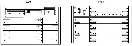
Figure 1-5 Enterprise 4500 System

Definitions of Terms
Centerplane - all Sun Enterprise X500 server systems use a centerplane. The orientation of the sockets on the rear of the centerplane is opposite the orientation of sockets on the front of the centerplane.
Board orientation - Boards in the front of the card cage are installed component side down, and boards in the rear of the card cage are installed component side up. Similarly, the orientation of the power/cooling modules installed in the rear of the system chassis is opposite the orientation of power/cooling modules in the front of the system chassis.
Viewer orientation - Since boards, modules, and power/cooling modules may be located on either side of the Enterprise server chassis centerplane, the terms "front," "rear," "right," and "left" are defined in Table 1-1.
Table 1-1 Definitions of Terms|
Orientation of the Server |
|
|
Front |
The key switch is located here. |
|
Rear |
The AC power switch and cable are located here. |
|
Orientation of Power/Cooling Module, Board, and UltraSPARC II Module |
|
|
Front |
Edge nearest you as you face the unit installed in a system |
|
Right |
Side to your right as you face the front of the installed unit |
|
Left |
Side to your left as you face the front of the installed unit |
Internal Options
Table 1-2 Internal Options for the Sun Enterprise Server Systems|
Option |
Enterprise 6500 |
Enterprise 5500/4500 |
Comments |
|---|---|---|---|
|
CPU/Memory+ boards, SBus+ I/O boards, Graphics+ I/O boards, and PCI+ I/O boards |
16, maximum |
8, maximum |
Each slot can accept any of these four types of boards: CPU/Memory+ board, SBus+ I/O board, Graphics+ I/O board, and PCI+ I/O board. Combinations can vary. One CPU/Memory+ board becomes the system master automatically. Jumper changes are not needed to select the system master. For easy cable connections, I/O+ boards should be installed at the rear of the card cage, although CPU/Memory+ boards and I/O+ boards will work in either the front or rear of the card cage. |
|
Disk boards |
2 per system (must use slot 15 if only 1 is installed) |
4 per system |
Can be installed only in slot 14 and slot 15 in the Enterprise 6500 system. For easier Disk boards cabling, CPU/Memory+ boards can be installed in the front and Disk boards in the rear of the Enterprise system. |
|
UltraSPARC II modules |
30 |
14 |
0-2 modules on each CPU/Memory+ board. |
|
Memory modules |
0, 8, or 16 SIMMs per CPU/Memory+ board |
0, 8, or 16 SIMMs per CPU/Memory+ board |
SIMM sizes are 8, 32, or 128 Mbyte DRAM. Do not mix sizes within the same bank. Add 8 SIMMs at a time. Install SIMMs in all bank 0 sockets first on each CPU/Memory+ board, from the lowest slot to the highest. Once bank 0 is full, install remaining SIMMs in bank 1 sockets in the same order. |
|
SBus cards |
15 per system |
7 per system |
0-3 cards per SBus+ I/O board, 0-2 cards per Graphics+ I/O board. |
|
Graphics (UPA) cards |
4 per system |
4 per system |
0-1 card per Graphics+ I/O board. |
|
PCI cards |
Dependent upon the type of PCI card, consult your customer representative |
Dependent upon the type of PCI card, consult your customer representative |
0-2 cards per PCI+ I/O board. |
|
Media tray |
CD-ROM and tape drive |
CD-ROM and tape drive |
Media tray takes removable-media drives only. One SunCD 32 is standard equipment per system. One optional tape drive is supported in the media tray. |
|
StorEdge(TM) Disk Array A5000 | See comments. | See comments. |
The Enterprise 6500 and 5500 system cabinets support Sun StorEdge(TM) A5000 disk arrays. The expansion cabinet also supports A5000 disk arrays. Refer to documentation that comes with the disk arrays and the expansion cabinet. |
|
StorEdge Flexipack or L400 | See comments. | See comments. |
The Enterprise 6500 and 5500 system cabinets support the StorEdge Flexipack or L400 tape unit. The expansion cabinet also supports the StorEdge Flexipack or L400 tape units. Refer to documentation that comes with the tape unit and the expansion cabinet. |
- © 2010, Oracle Corporation and/or its affiliates
