Replacing or Installing a PCI Card
-
Ensure that the voltage type of the PCI card you are replacing or installing matches the voltage type of the riser card, either 5.0V or 3.3V.
-
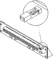
Verify that the JTAG Test Jumper is removed/disabled (Figure 4-28).
Note -PCI+ I/O boards purchased from Sun Microsystems are shipped with the JTAG Test Jumper disabled or removed on both of the 5.0V riser cards installed on the board.
Figure 4-28 JTAG Test Jumper

-
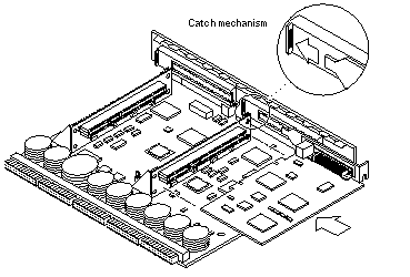
Align the PCI card so that the PCI bus connector mates with the PCI+ I/O board PCI bus connector, making sure that the external connector end of the card is retained on one side by the opening in the metal catch mechanism and the opposite end is properly aligned to accept the locking thumbscrew (Figure 4-29).
Figure 4-29 PCI Card Installation/Replacement

-
Once the card is properly positioned as described above and seated properly to the PCI board PCI Bus connector, tighten the locking thumbscrew.
Note -Some PCI cards may not require the standoffs provided for mounting.
-
Ensure that the standoff is positioned to capture the edge of the PCI card, and then tighten the screw securing the standoff.
-
Use the procedures in the "Installing a Board", to replace the I/O+ board.
- © 2010, Oracle Corporation and/or its affiliates
