Appendix B Modem and Null Modem Cables
This appendix provides the pinouts of cables that can be used for most modem and null modem configurations. Refer to the manufacturer's documentation for a detailed description of special cables you may need to connect your particular modem.
Standard EIA-232-E Modem Cables
Use the cable shown in Figure B-1 to connect a standard EIA-232-E serial port a synchronous modem:
Figure B-1 Synchronous EIA-232-E Modem Cable

Use the cable in Figure B-2 to connect a standard EIA-232-E serial port to an asynchronous modem:
Figure B-2 Asynchronous EIA-232-E Modem Cable
IPC/IPX Adapter Cables
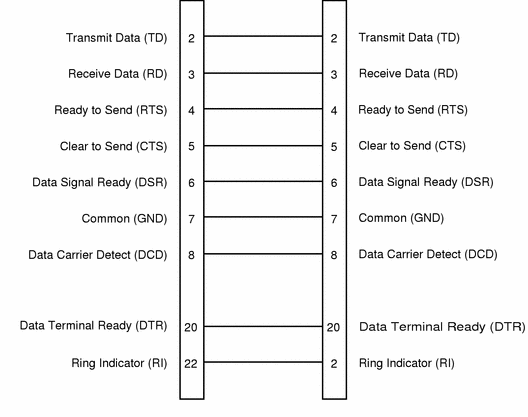
Figure B-3 and Figure B-4 show the pinouts for a cables used to convert the 8-pin serial port on a SPARCstation IPC or IPX to an EIA-232-E serial port.
Figure B-3 Synchronous IPC/IPX Adapter Cable

Figure B-4 Asynchronous IPC/IPX Adapter Cable
Asynchronous EIA-232-E Null Modem
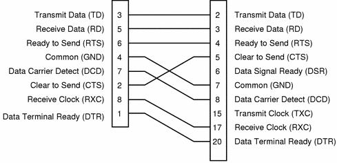
Use the cable shown in Figure B-5 to create a direct asynchronous connection between two hosts:
Figure B-5 Asynchronous EIA-232-E Null Modem
Synchronous EIA-232-E Null Modems
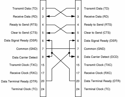
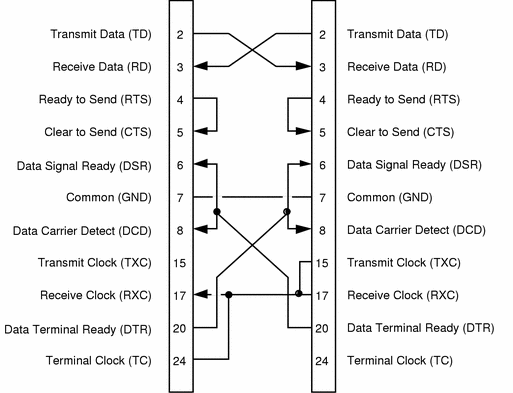
Use the cable shown in Figure B-6 to create a direct synchronous connection between two hosts when both sides provide a clock signal:
Figure B-6 Synchronous EIA-232 Null Modem (both sides provide clock)
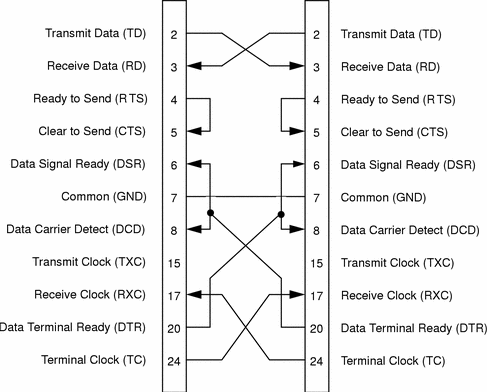
Use the cable shown in Figure B-7 to create a direct synchronous connection between two hosts when only one side provides a clock signal:
Figure B-7 Synchronous EIA-232 Null Modem (one side supplies clock)
Synchronous EIA-449 Null Modems
The high-speed serial interface for Sbus (HSI/S) has a 37-way EIA-449 port. This type of port uses balanced transmission to provide improved speed and distance characteristics; therefore, there are two pins for each signal.
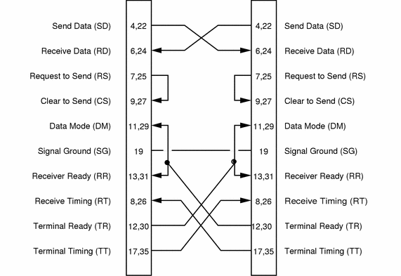
When both sides of the connection provide a clock signal, pins 17 and 35 (Terminal Timing) and pins 8 and 26 (Receive Timing) are crossed-over, as shown in Figure B-8.
Figure B-8 Synchronous EIA-449 Null Modem (both sides supply clock)
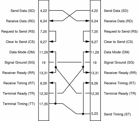
When one side of the connection provides a clock signal, pins 17 and 35 (Terminal Timing) on one side are connected to pins 8 and 26 (Receive Timing) on both sides, as shown in Figure B-9.
Figure B-9 Synchronous EIA-449 Null Modem (one side supplies clock)
X.21 to EIA-449 Converter
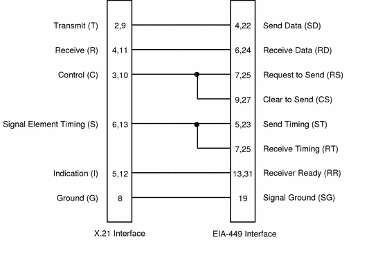
Use the cable shown in Figure B-10 to convert between standard X.21 and EIA-449 interfaces:
Figure B-10 X.21 to EIA-449 Converter
- © 2010, Oracle Corporation and/or its affiliates
