N1 Provisioning Server Concepts
This section provides summaries of the major N1 Provisioning Server logical components.
Administration
Administrative functionality for N1 Provisioning Server software and an I-Fabric is available in two forms: through the Administration screen within the Control Center and alternatively, by a set of command-line interface tools that interface directly with the Control Center.
Control Center
The Administration screen is the central point of administration within the Control Center. Using the Control Center from the Control Center Management PC, you can define classes of users that have access to the administration screen and its associated functionality. From the Control Center Administration screen, you have a comprehensive view of all users and logical server farms within an I-Fabric. You can do the following tasks from the Control Center Administration screen:
-
Create and delete logical server farms
-
Create and delete accounts
-
Set usage limits
-
Set user and administrator access privileges
-
Add and remove logical server farms
-
Add images to the image repository
-
Remove images from the image repository
-
Create and remove contracts
-
Publish pertinent news items to accounts
You also can manage security rights and administration privileges from the Administration screen. The Control Center has three levels of access privileges:
-
User Level – A standard user level that permits access to logical server farms within an account
-
Account Manager Level – A manager within an account that permits the ability to add and delete users within an account
-
Administrator – The highest level of access that permits access to the entire I-Fabric (including the control plane) as well as all accounts
For more information about the Control Center, see N1 Provisioning Server 3.1, Blades Edition, Control Center Management Guide.
For more information about access privileges, see Applying Role-Based Access Control in N1 Provisioning Server 3.1, Blades Edition, System Administration Guide.
Command-Line Tools
The command-line tools provide an interface to the Control Center that is used for managing an I-Fabric in conjunction with the Control Center administration functionality. The tools offer a more granular level of control, and also provide an interface for accessing devices and configuration data.
The tools are commonly used to view and track resources within an I-Fabric. Using the command line tools, you can:
-
Check the state of any devices within an I-Fabric
-
Trace details, such as physical Ethernet connectivity, from the network interface port in the device back to the physical port on the Ethernet switch within an I-Fabric
-
Track and manage the logical assignment of physical devices and ports to logical server farms
-
Manage VLANs and subnets within logical server farms
-
Update the physical resource pool of an I-Fabric
When a device, such as a server blade, is added to an I-Fabric, the command-line tools facilitate the wiring and configuration auditing required for integrating the new device into the available resource pool. Command-line tools also assist in the management of software images, the reconfiguration of devices, and the activation and updating of logical server farms.
For a list of the available command-line tools and a brief description of each tool, Appendix B, Command-Line Tools in N1 Provisioning Server 3.1, Blades Edition, System Administration Guide.
Resource and Network Virtualization
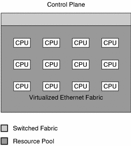
An important aspect of the design of N1 Provisioning Server software is the virtualization provided for all the hardware devices within the resource pool of an I-Fabric. This virtualization enables the rapid and dynamic association of devices to network connectivity and provides the capability to create a logical server farm from a pool of physical devices within an I-Fabric. Virtualization of network connectivity provides the foundation for deploying drag-and-drop connectivity between devices that can then be logically wired together.
Figure 1–4 Control Plane Resource Virtualization

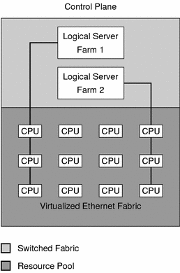
Virtualization of the network provides security, and enables the transparent management, configuration, and allocation of network devices. N1 Provisioning Server software utilizes VLANs and automates all aspects of VLAN configuration to enable network virtualization.
Network virtualization provides two distinct benefits:
-
Customized virtual wiring is created for each logical server farm. N1 Provisioning Server Network virtualization enables you to create arbitrary network topologies, associate subnet addresses, and assign IP addresses to servers and network devices placed on the subnets. You can add and remove resources from the logical server farm while automatically configuring newly added and existing devices in the logical server farm as necessary.
-
For provisionable devices, the N1 Provisioning Server software performs secure partitioning at the Layer 2 network layer by taking sets of network ports on a large-scale switched fabric and placing them on a protected Layer 2 virtual network. Each virtual network uses physical port-based virtual local area network (VLAN) technology built into current generation Layer 2 switches.
Figure 1–5 Control Plane Network Virtualization

Logical Server Farms
The control plane, switched fabric, and resource pool work together to dynamically create logical server farms within an I-Fabric. Logical server farms are securely allocated from the Resource Pool and managed by N1 Provisioning Server software. N1 Provisioning Server software creates server farms from the resources available within the Resource Pool. Logical server farms are built using the same physical resources as traditional server farms but they are established and managed under the flexible control of N1 Provisioning Server software. Logical server farms are analogous to traditional, manually built, dedicated server farms except that you can create, grow, shrink, and delete them as data structures that reside within N1 Provisioning Server software.
Logical server farms have the same performance and control characteristics as traditional server farms. N1 Provisioning Server software is not in the data path and does nothing to limit the performance of the devices or prevent the logical server farm from running at wire speed.
Secure partitions enforced by N1 Provisioning Server software and methodologies enable you to exercise independent administrative control over each logical server farm. Even though the user of a specific logical server farm has full administrative access on all devices within that farm, the user cannot view, access, or modify the devices or data associated with a different logical server farm.
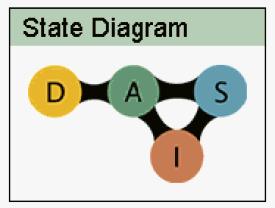
The following graphic illustrates the life cycle of a logical server farm in the Control Center.
Figure 1–6 Logical Server Farm States

-
D – Design State
-
A – Active State
-
S – Standby State
-
I – Inactive State
For more details on how to manage logical server farms, see Chapter 4, Building, Updating, and Monitoring Server Farms in N1 Provisioning Server 3.1, Blades Edition, Control Center Management Guide.
Description Languages
A logical server farm within an I-Fabric is constructed from a number of basic building blocks. Capturing a logical description of these building blocks and their interrelationships enables the creation of a digital blueprint that specifies a farm's logical structure. This logical blueprint facilitates the automation of many manual tasks involved in constructing logical server farms.
N1 Provisioning Server software uses the following three description languages to capture logical descriptions of server farms:
-
FML is an XML dialect used to represent the logical blueprint of a logical server farm. FML is scalable and capable of describing, with a high degree of abstraction, network and configuration data for servers within a logical server farm.
The general structure of FML is to describe an I-Fabric as a structure composed of sets of devices that have both connectivity as well as configuration-related information. The connectivity information describes how these various devices are interconnected, for example, how device Ethernet ports are connected to specific subnets and VLANs. In addition to devices and their interconnectivity, FML provides the ability to describe roles that servers may occupy within a logical server farm, for example, a web server, database server, and application server. This ability enables the Control Center to deploy multiple instances of a given server within a logical server farm.
FML also enables the replication of entire logical server farms. Such replication might be required for creating site mirrors at different geographic locations, implementing business continuance solutions, or for creating a testing and staging area for a future version of a logical server farm.
-
Monitoring Mark-Up Language (MML)
MML is an XML dialect that describes monitor deployments and configurations as defined using the Control Center. MML describes monitoring configurations as they pass from the control center to the provisioning server.
-
Wiring Mark-Up Language (WML)
WML is an XML dialect that describes the physical wiring characteristics within an I-Fabric. WML is also used to describe the physical wiring of an I-Fabric. The difference between FML and WML is that FML describes the logical device wiring of a logical server farm and layout, whereas WML describes the physical wiring of all the devices present within an I-Fabric.
Network Packages
N1 Provisioning Server software runs with the following network packages:
-
Packet filtering – TSPRipf
The TSPRipf tool filters IP packets based on configurable packet characteristics, such as protocol, port number, source address, or destination address. Each service processor has one packet filtering tool installed to prevent malformed or malicious packets from one account's network entering another account's network or the Control Center network. The tool is statically configured by the Control Center at installation time. The default configuration denies any packets not specifically used by the Control Center.
-
Network API – TSPRnetcf
This API defines the Java™ interfaces for networking configuration on the Control Center server. The network API supports the DHCP and DNS protocols.
-
The DHCP protocol implementation is based on the public domain package from the Internet Software Consortium (http://www.isc.org). The service processor uses the DHCP facility to configure the servers in a logical server farm with their hostname and IP addresses. The DHCP configuration information for a logical server farm is stored in the control plane database (CPDB) for persistency and ease of migrating a logical server farm from one service processor to another. The information in the CPDB is used to create the DHCP configuration file /etc/dhcp.conf at logical server farm activation time.
In the service processor, the TSPRdhcp utility assigns IP addresses and parameters to hosts, thus enabling the setup of IP addresses and parameters without having to modify or reboot the host. The utility does not allocate IP addresses. IP addresses are allocated by the Farm Manager.
Note –Do not edit the dhcpd.conf file. dhcpd.conf is maintained by the N1 Provisioning Server software.
-
The DNS protocol implementation is based on the public domain package from the Internet Software Consortium (http://www.isc.org). The service processor uses the DNS facility for hostname resolution for servers and network devices in a logical server farm. The service processor that owns the logical server farm also serves as the DNS server for the logical server farm. The DNS information is stored in the CPDB for persistency and ease of migrating a logical server farm from one service processor to another. The information in the CPDB is used to create the DNS configuration file etc/named.conf at logical server farm activation time.
Note –Do not manually edit the named.conf. named.conf is dynamically updated by the service processor.
Hardware Abstraction Layer
Hardware Abstraction Layers (HALs) are sets of application programming interfaces (APIs) that provide device independence for the Control Center software. HALs are used to automate the interaction with physical devices within an I-Fabric. The HAL module translates abstract Control Center actions into device-specific commands. HALs might provide interfaces to specific manufacturer's Ethernet switches.
Because the Control Center software deals with only the abstract behavior of the device, HALs enable the Control Center software to manage different devices that exhibit the same overall behavior but might differ in how they are configured and managed. This difference could exist because the equipment is from different manufacturers or because of differences between current and next-generation products.
- © 2010, Oracle Corporation and/or its affiliates
