Connecting the Chassis to the Control Plane Server and Switches
This section provides the procedures for connecting the control plane server, blade system chassis, Control Center Management PC, and switches for each of the supported configurations.
Connecting a Single Chassis with a Single SSC
This section illustrates the topology of a single-chassis single-SSC I-Fabric, and provides the procedure for connecting the I-Fabric components.
The SSC must be installed in chassis slot SSC0 for a single chassis, single SSC configuration. The Provisioning Server software cannot configure and provision the server blades if the SSC is installed in SSC1.
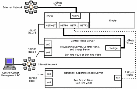
Figure 3–3 Single Chassis With a Single SSC and no External Switch

 To Connect A Single Chassis With a Single SSC to the Control
Plane Server
Steps
-
Connect the NETMGT port of SSC0 to the eri0 port of the control plane server with 100 base T copper Ethernet cable.
-
Connect the NETP0 port of SSC0 to the ce0/skge0 port of the control plane server with 1000 base T copper Ethernet cable.
-
Connect the NETP7 port of SSC0 to the external network with 1000 base T copper Ethernet cable. Farms are accessed through the NETP7 connection.
-
Connect the eri1 port of the control plane server to your internal network switch with 100 base T copper Ethernet cable.
-
Connect the Control Center Management PC NIC port to the internal network switch.
The type of cable depends on the capacity of the PC NIC and the network switch ports.
-
If you have chosen to install the image server as a separate machine, connect the image server ports as follows.
-
Connect the NETP1 port of SSC0 to the NIC port of the image server machine
Use a cable appropriate for the type of interface card installed in the image server: 100 base T copper for a 10/100 base T NIC, and 1000 base T copper for a gigabyte-capable NIC.
Note –If you have chosen to install the N1 image server on a separate machine, install a gigabyte-capable card such as the Sun GigaSwift NIC or the SysKonnect NIC in the image server machine.
-
If you have a separate image server machine, connect the eri0 port of the image server to your internal network switch with 100 base T copper Ethernet cable.
-
Connecting a Single Chassis with Two SSCs
This section illustrates the topology of a single-chassis dual-SSC I-Fabric, and provides the procedure for connecting the I-Fabric components.
Note –
For security, install a separate control plane switch and data plane switch. Use of a single switch for the control plane and data plane is not supported for an installation where any chassis contains two SSCs.
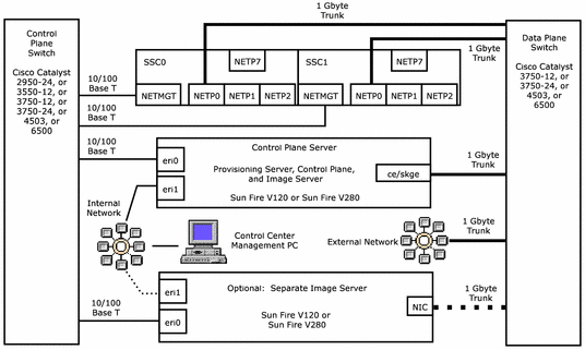
Figure 3–4 Single Chassis with Two SSCs and Separate Control Plane and Data Plane Switches

 To Connect A Single Chassis with Dual SSCs to the Control
Plane Server and Switches
Steps
-
Connect the NETMGT ports of SSC0 and SSC1 to the control plane switch with 100 base T copper Ethernet cable.
-
Connect the NETP0 ports of SSC0 and SSC1 to a data plane switch gigabit port with 1000 base T copper Ethernet cable.
-
Connect the ce0/skge0 port of the control plane server to data plane switch gigabit port with 1000 base T copper Ethernet cable.
-
Connect the eri0 port of the control plane server to a 100 base T port on the control plane switch with 100 base T copper Ethernet cable.
-
Connect the eri1 port of the control plane server to the internal network switch with 100 base T copper Ethernet cable.
-
Connect the Control Center Management PC NIC port to the internal network switch.
The type of cable depends on the capacity of the PC NIC and the network switch ports.
-
Connect the data plane switch to the external network with 1000 base T copper Ethernet cable. Farms are accessed through this connection.
-
If you have chosen to install the image server as a separate machine, connect the image server ports as follows.
-
Connect the eri0 port of the image server to a 100 base T port on the control plane switch with 100 base T copper Ethernet cable.
-
Connect the eri1 port of the image server to the internal network switch with 100 base T copper Ethernet cable.
-
Connect the NIC port of the image server to a port with the same bit-rate capacity on the data plane switch.
Use a cable appropriate for the type of interface card installed in the image server and control plane switch: 100 base T copper for a 10/100 base T NIC, and 1000 base T copper for a gigabyte-capable NIC.
Note –If you have chosen to install the N1 image server on a separate machine, install a gigabyte-capable card such as the Sun GigaSwift NIC or the SysKonnect NIC in the image server machine.
-
Connecting Two or More Chassis
This section illustrates the topology of a two or more chassis I-Fabric, and provides the procedure for connecting the I-Fabric components.
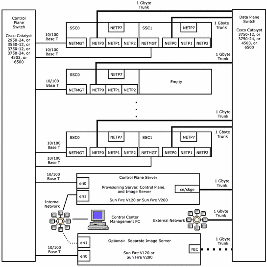
Figure 3–5 Two or More Chassis with Separate Control Plan and Data Plane Switches

 To Connect Two or More Chassis to the Control Plane Server
and Switches
Steps
-
For each chassis, perform the following steps:
-
Connect the NETMGT port of SSC0 to the control plane switch with 100 base T copper Ethernet cable.
-
Connect the NETP0 port of SSC0 to a data plane switch gigabit port with 1000 base T copper Ethernet cable.
-
If SSC1 present, connect the NETMGT port of SSC1 to the control plane switch with 100 base T copper Ethernet cable.
-
If SSC1 present, connect the NETP0 port of SSC1 to a data plane switch gigabit port with 1000 base T copper Ethernet cable.
-
-
Connect the ce0/skge0 port of the control plane server to data plane switch gigabit port with 1000 base T copper Ethernet cable.
-
Connect the eri0 port of the control plane server to a 100 base T port on the control plane switch with 100 base T copper Ethernet cable.
-
Connect the eri1 port of the control plane server to the internal network switch with 100 base T copper Ethernet cable.
-
Connect the Control Center Management PC NIC port to the internal network switch.
The type of cable depends on the capacity of the PC NIC and the network switch ports.
-
Connect the data plane switch to the external network with 1000 base T copper Ethernet cable. Farms are accessed through this connection.
-
If you have chosen to install the image server as a separate machine, connect the image server ports as follows.
-
Connect the eri0 port of the image server to a 100 base T port on the control plane switch with 100 base T copper Ethernet cable.
-
Connect the eri1 port of the image server to the internal network switch with 100 base T copper Ethernet cable.
-
Connect the NIC port of the image server to a port with the same bit-rate capacity on the data plane switch.
Use a cable appropriate for the type of interface card installed in the image server and control plane switch: 100 base T copper for a 10/100 base T NIC, and 1000 base T copper for a gigabyte-capable NIC.
Note –If you have chosen to install the N1 image server on a separate machine, install a gigabyte-capable card such as the Sun GigaSwift NIC or the SysKonnect NIC in the image server machine.
-
Connecting Terminal Servers
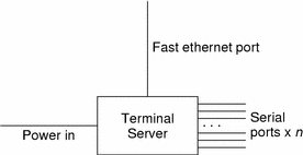
Connecting a terminal server to the control plane is optional. The terminal server typically has power in, one Ethernet port, and 32 serial ports out, as shown in the following figure.
Figure 3–6 Terminal Server Connections

Serial connections allow out-of-band access to certain devices. Devices with serial connections have their ports labeled s0, s1, and so forth. Terminal servers have their ports labeled with a number, for example, 1, 2, 3, and so forth.
Note –
Only the control plane server, image server, and the chassis SSC switch controller and system controller are automatically discovered during the installation process. Other devices, such as terminal servers, are not added to the database.
The connection guidelines for a terminal server are as follows:
-
Connect the terminal server to a power controller or constant power.
-
Connect the terminal server serial port to the control plane switch.
-
Connect the terminal server Fast Ethernet port to a control plane switch port.
- © 2010, Oracle Corporation and/or its affiliates
