Physical Components
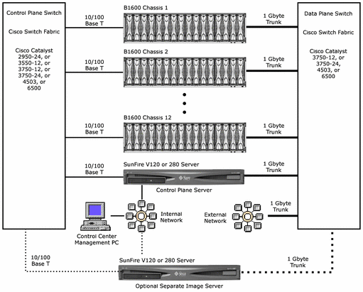
The following diagram is an example of the hardware that comprises a typical N1 Provisioning Server system.
Figure 1–1 Representative N1 Provisioning Server System

The following sections describe the hardware components shown by the above diagram.
Sun Fire B1600 Blade System Chassis
Each blade system chassis contains the following components:
-
One or two chassis switch and system controllers (SSCs). An SSC must be installed in SSC0 in each chassis.
-
One or more of the following server blades:
-
B100s: SPARC architecture, Solaris Operating System
-
B100x: Single processor x86 architecture, Solaris x86 or Linux operating system
-
B200x: Dual processor x86 architecture, Solaris x86 or Linux operating system
Note –The B200x blade occupies 2 chassis slots and is treated as an unmanaged device.
-
B10n: Content Load balancing blade
-
B10p: SSL Proxy blade
Note –The SSL proxy blade is treated as an unmanaged device.
-
Each blade system chassis can support up to 8 B200x server blades, or 16 single-slot server blades.
Control Plane Server
The control plane server hosts all N1 Provisioning Server software, which includes the control plane software, the control plane database (CPDB), the Control Center server and database, the Control Center software, and, in a standard install, the N1 Provisioning Image Server.
Control Center Management PC
The Control Center Management PC provides access to the Control Center software using a web browser-based user interface. The Control Center is used to design and deploy logical server farms, and to define numerous characteristics including network topology, storage requirements, monitors, and alerts. The Control Center is also used to define the kinds of monitoring you want to perform. The monitoring definition is saved using the Monitoring Mark-up Language (MML).
N1 Image Server
The N1 Image Server (N1 IS) is used to store operating system disk images for each type of server blade in a chassis, and to load the disk images to server blades using the JumpStartTM and Flash archives depending on the type of server blade and operating system. The image server is typically installed on the control plane server. If desired, the image server can be installed on a separate machine.
Note –
For best results, use a Gigabit copper Network Interface Card (NIC) for the image server.
Control Plane Switch and Data Plane Switch
The control plane switch connects all management and control interfaces on a designated control subnet and virtual local area network (VLAN). The control plane switch is optional only for a single blade system chassis installation in which the chassis contains a single switch and system controller (SSC). The control plane switch is required for an installation if any chassis contains two SSCs or if there is more than one chassis.
The data plane switch provides connectivity between the control plane Server, the N1 image server, the blade system chassis SSCs and server blades, and your network.
- © 2010, Oracle Corporation and/or its affiliates
