 Dual-Core CPU configuration to an AMD Opteron Quad-Core or Enhanced Quad-Core CPU configuration. To perform the procedures in this document, you must have the correct kit for your type of upgrade. There are two kits.
|
Quad-Core CPU Upgrade Kit Installation Guide |
The instructions provided in this document describe how to use the Quad-Core CPU Upgrade Kits to upgrade your Sun Fire X2200 M2 server from a dual-core CPU configuration to a quad-core CPU configuration.
This document includes the following sections:
| Note - This kit is available as a customer replaceable unit (CRU). If you need assistance, contact your Sun Microsystems service representative. |
The procedures in this document describe how to use the quad-core upgrade kits to upgrade a Sun Fire X2200 M2 server from an AMD Opteron Dual-Core CPU configuration to an AMD Opteron Quad-Core or Enhanced Quad-Core CPU configuration. To perform the procedures in this document, you must have the correct kit for your type of upgrade. There are two kits.
The following table lists the CPU upgrade options that are available using the upgrade kits and this document. To use the table, locate your current configuration and match it to the new configuration. The hardware required is listed in the last column.
|
1-Enhanced Quad-Core CPU Upgrade Kit Note - Kit contains two CPUs. Use one CPU in socket CPU0 only. |

|
Caution - Do not mix CPU types on the same motherboard. |
The kits are available as dual CPU server configurations only. See the next section, Upgrade Kit Contents, for the kit contents.
|
To order, contact your Sun Account Manager or your Sun authorized reseller. |
|
The time required to complete this upgrade: 45 - 60 minutes.
In addition to the two quad-core upgrade kits, an Enhanced Quad-Core CPU X-option is also available. The X-option contains one AMD Opteron Enhanced Quad-Core CPU and one heatsink and is used for upgrading from a quad-core CPU to an enhanced quad-core CPU. The X-option provides the following quad-core-to-enhanced quad-core upgrade paths:
|
1-Enhanced Quad-Core CPU X-Option Note - Use one CPU in socket CPU0 only. Update to enhanced quad-core BIOS before upgrading. |
| Note - The Enhanced Quad-Core CPU X-Option does not contain a firmware PROM. |
The X-Option does not contain a firmware PROM. Therefore, it does not contain the necessary hardware to upgrade a dual-core CPU server to an enhanced quad-core CPU server. For this upgrade path, you must use the Enhanced Quad-Core CPU Upgrade Kit.
For CPU replacement procedures using the Enhanced Quad-Core CPU X-option, see the Sun Fire X2200 M2 Server Service Manual.
This section lists software, hardware, and firmware issues related to upgrading your server from dual-core processors to quad-core processors.
Some Micron 4 GB DIMMs supplied for use with dual-core CPU servers can have single-bit or multiple bit errors after the servers are upgraded to quad-core CPUs. Symptoms include system crash and boot failure. Not all existing Micron 4 GB DIMMs are affected.
Before you upgrade your server to quad-core CPUs, you should inspect the label on any 4 GB DIMMs installed in your server. Affected DIMMs have the following three identifiers on the label:
For more information, see the Sun Fire X2200 M2 Server Product Notes.
Sun Fire X2200 M2 Server Product Notes
Sun Fire X2200 M2 Server Service Manual
Sun Fire X2200 M2 Server Installation Guide
Embedded Lights Out Manager Administration Guide for the Sun Fire X2200 M2 and X2100 M2 Servers
Sun Fire X2200 M2 server product documentation is available at:
http://docs.sun.com/app/docs/prod/sf.x2200m2#hic
Upgrading a dual-core CPU server to a quad-core CPU server involves performing the following steps:
1. Safety Information and ESD Prevention
2. Reviewing Product Note Documentation
3. Downloading the Tools and Drivers CD
4. Recording Your Current BIOS settings
5. Preparing the Server for the Upgrade
1. Removing the Air Duct and Heatsinks
3. Installing the Quad-Core CPUs
4. Installing the New Heatsink
5. Replacing the Firmware PROM
6. Installing the New Firmware PROM
1. Preparing the Server for Operation
4. Performing Power On and BIOS Setup Procedures
1. Returning Parts to Sun Microsystems
Before you begin the upgrade procedure, you must understand the safety information and electrostatic discharge and antistatic prevention measures.
This section describes important safety information that you need to know prior to removing or installing parts in your Sun Fire X2200 M2 server.

|
Caution - Hazardous voltage present. Never attempt to run the server with the covers removed. |

|
Caution - Equipment damage possible. The covers must be in place for proper air flow. |
For your protection, observe the following safety precautions when setting up your equipment:
Electrostatic discharge (ESD) sensitive devices, such as the motherboards, PCI cards, hard drives, and memory modules, require special handling.

|
Caution - You must disconnect the power supply before servicing any of the components documented in this chapter. |
Wear an antistatic wrist strap and use an antistatic mat when handling components such as hard drive assemblies, circuit boards, or PCI cards. When servicing or removing server components, attach an antistatic strap to your wrist and then to a bare metal area on the chassis. Following this practice equalizes the electrical potentials between you and the server.
| Note - An antistatic wrist strap is included in the upgrade kit. |
Place static-sensitive components such as motherboards, memory, and other PCBs on an antistatic mat.
1. Prepare an antistatic surface to set parts on during the removal, installation, or replacement process.
Place static-sensitive components such as the printed circuit boards, memory modules, and CPUs on the antistatic mat. The following items can be used as an antistatic mat:
2. Attach an antistatic wrist strap.
When servicing or removing server components, attach an antistatic strap to your wrist and then to a bare metal area on the chassis. Proceed to the next section, Preparing for the Upgrade.
Step |
||
|---|---|---|
1 |
||
2 |
||
3 |
The Sun Fire X2200 M2 Server Product Notes contains updated information about issues and developments for your server. Before you begin the quad-core CPU upgrade, review this document.
|
 View or download the latest revision of the Sun Fire X2200 M2 Server Product Notes at:
http://docs.sun.com/app/docs/prod/sf.x2200m2
To upgrade the server to quad-core CPUs you must update the firmware using the firmware available on the Sun Fire X2200 M2 Server Tools and Drivers CD v2.0 (or later). The CD is available online as an ISO image. You need to download the ISO image and burn a CD to use after you perform the hardware upgrade of your server.
| Note - For the quad-core upgrade, the server’s service processor (SP) firmware must be upgraded to the firmware level v3.15. |
|
1. Download the Sun Fire X2200 M2 Server Tools and Drivers CD v2.0 (or later) ISO image at:
http://www.sun.com/servers/x64/x2200/downloads.jsp
2. From the description of the contents of the Tools and Drivers CD, make note of the BIOS firmware version number.
3. Burn a CD using the ISO image.
4. Retain the CD for use after the server hardware upgrade.
To upgrade your dual-core server to quad-core or enhanced quad-core CPUs, you need to replace the firmware PROM, which contains the default BIOS settings. If you had previously customized the BIOS by changing the default settings, then you need to access the BIOS Setup Utility and record those changes before you begin this upgrade procedure. After the upgrade is finished, you must enter the BIOS Setup Utility again to customize the BIOS settings.
The method described here for accessing the BIOS Setup Utility involves attaching a keyboard, video, and mouse (KVM) to the server. You can also use the Remote Console application in the Embedded Lights Out Manager’s (ELOM) web GUI and the Remote Power Control submenu to boot directly to the BIOS Setup Utility. For information about the Remote Console application, see the Sun Fire X2200 M2 Installation Guide and the Embedded Lights Out Manager Administration Guide.
1. Attach a KVM to the server, so that you can view the power-on self test (POST) messages.
2. Boot the server, and watch the POST messages as they appear on the display.
3. When prompted, press the F2 key to enter the BIOS Setup Utility screens.
The BIOS Setup Utility screen appears.
4. Use the arrow keys to scroll through the BIOS Setup Utility screens and record your customized settings.
5. To exit the BIOS Setup Utility press the Esc key or the F10 key.
Preparing the server for the upgrade involves placing the server in an area that provides enough space and light to allow you to perform the steps in each procedure safely and easily.
|
1. Perform a clean shutdown of the operating system.
Use the OS-specific shutdown procedure.
4. Power off and remove all peripheral devices connected to the server.
5. Label and disconnect all cables connected to the server.
Use tape, color-coding, or some other scheme that will assist you in cabling the system at the end of the upgrade.
6. Remove the server from the rack.
For more information, see the Sun Fire X2200 M2 Server Service Manual.
7. Place the server on a flat surface.
Choose a surface with an ample amount of surrounding work space.
8. To remove the server cover, use a #2 Phillips screwdriver to loosen the two captive screws located on the rear of the server (see FIGURE 1).
9. Remove the cover and set aside.
FIGURE 1 Removing the Server Cover
10. Put the anti-static wrist strap on your wrist. If necessary, connect the grounding cord to the wrist strap, and connect the other end (clip end) of the cord to bare metal on the server chassis.
The strap should fit snugly enough on your wrist so that the metal contact point constantly touches bare skin.
11. Inspect the interior of the server, and, if necessary, use compressed air to remove dust from the server.
Use the figure to identify and familiarize yourself with the components referenced in these procedures.
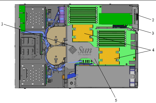
Proceed to the next section, Removals and Replacements.
Step |
||
|---|---|---|
1 |
||
2 |
||
3 |
||
4 |
||
5 |
||
6 |
||
7 |
| Note - Retain all packaging materials and old heatsinks and CPUs for return to Sun Microsystems, Inc. |
Before you can upgrade the CPUs, you must first remove the air duct and the heatsinks. The Sun Fire X2200 M2 heatsink is a passive thermal dissipation device that helps to move heat away from the CPU. The air duct provides a concentrated flow of air from the system fans to the heatsinks. The heatsinks sit atop the CPUs, and are secured to the motherboard with four screws. A thin layer of thermal compound is between the top of the CPU and the bottom of the heatsink. In addition to facilitating the transfer of heat away from the CPU to the heatsink, this compound also acts as an mild adhesive.

|
Caution - The heatsink can become hot. Allow sufficient time for cooling before handling. |
|
1. Use a #1 Phillips screwdriver to remove the air duct retaining screw (see FIGURE 2).
FIGURE 2 Removing the Air Duct Retaining Screw
Set the air duct and retaining screw aside.
3. To remove the heatsink, gently press down on the center of the heatsink, and use a #2 Phillips screwdriver to loosen the four captive screws that secure the heatsink to the motherboard (see FIGURE 3).
The four captive screws are spring-loaded. Pressing down slightly on the center of the heatsink relieves the spring tension.
FIGURE 3 Removing the Heatsink
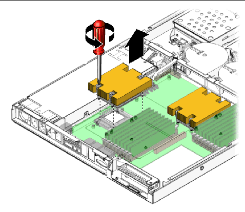
The heatsink assembly is also secured to the top surface of the CPU by a layer of thermal compound, which acts as an adhesive.
4. Grip the sides of the heatsink, and while pulling slightly upward, wiggle the heatsink right and left to break the adhesive seal created by the thermal compound.
5. Place the heatsink upside-down on a flat surface to prevent the thermal compound from contaminating the work area and other components.
6. Repeat Step 1 through Step 5 to remove the other heatsink.
7. Proceed to the next section, Removing the CPUs.
The CPUs are secured in the socket by a CPU retaining cover. To open the CPU retaining cover, you must unlock the retaining cover release lever. The release lever is located on one side of the socket and is held in place by a clip.
|
1. Gently push down on the socket release lever, and move the lever slightly away from the CPU.
This action frees the lever, which is held in place by a clip.
2. Lift the lever to the fully open position (see FIGURE 4).
3. Lift the hinged CPU retaining cover to the fully open position (see FIGURE 4).
| Note - The top of the CPU might have a residual layer of thermal compound. |
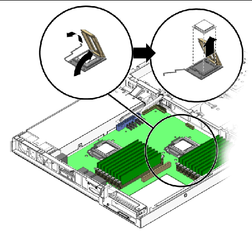
4. Lift the CPU out of the socket (see FIGURE 4).
Leave the release lever and the CPU retaining cover in the fully open position.
5. Set the CPU aside, taking care to prevent the thermal compound from contaminating the work area and other components
6. Repeat Step 1 through Step 5 for the other CPU.
7. Proceed to the next section, Installing the Quad-Core CPUs.
The CPU and CPU socket are keyed to assist you in proper installation. Both the CPU and the CPU socket are marked with a small triangle in one corner. Some CPU sockets might have a corner that is trimmed instead of marked with a triangle. This trimmed corner also acts as the key. When installing the CPU, align the triangle on the CPU with the triangle or trimmed corner on the CPU socket.
|
| Note - If you are installing a single CPU only, the CPU must be installed in socket CPU0. |
1. Unpack the new quad-core CPUs from the upgrade kit.
Handle the CPU with care. Do not touch the metal contacts.
2. Ensure that the socket release lever and the CPU retaining cover are in the fully open position (see FIGURE 4).
3. Align the keyed CPU corner with the keyed CPU socket corner.
The CPU has a small triangle mark on one corner. The CPU socket has a similar mark on one corner. This mark is the key, indicating proper positioning of the CPU in the CPU socket (see FIGURE 5).
FIGURE 5 Installing CPU Using Triangular Key Marks
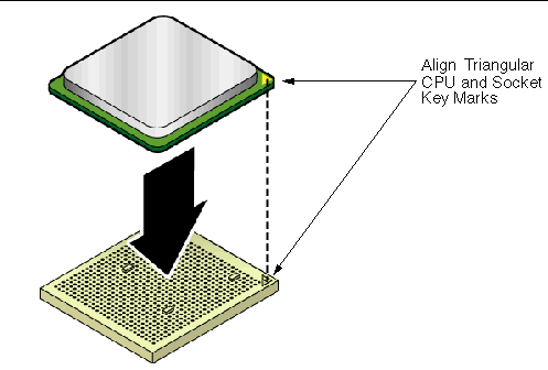
4. Gently place the CPU onto the CPU socket (see FIGURE 6). Do not press down on the CPU. The CPU does not need to be forcibly seated or inserted.
The CPU should be lying flat on the socket. It should not be skewed or sitting unevenly. When properly positioned the CPU fits snugly in the CPU socket.
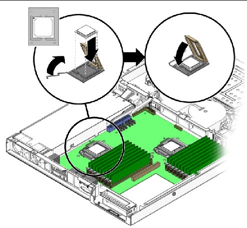
5. Close the CPU retaining cover (see FIGURE 6).
6. To secure the CPU in the socket, rotate the socket release lever down until it snaps into place under the lever retaining clip.
7. To install the other quad-core CPU, repeat Step 1 through Step 6.
8. Proceed to the next section, Installing the New Heatsink.
The new heatsink has the thermal compound pre-applied. This compound is protected by a thin plastic cover, which you must remove before installing the heatsink onto the CPU.
|
1. Remove the heatsink from the upgrade kit.
2. Remove the plastic cover that protects the thermal compound.
3. Position the heatsink over the CPU. Allow the captive screws in the heatsink to dangle, and align the screws with the screw holes on the motherboard.

|
Caution - Thermal damage to the CPU can occur if the heatsink is moved too much during installation. The layer of thermal grease might become uneven, leading to component damage. |
4. Gently lower the heatsink onto the CPU.
5. To attach the heatsink to the motherboard, alternately tighten the four screws by turning each screw approximately 180 degrees (see FIGURE 7).
The captive heatsink screws are spring-loaded. To counteract the springs, you might need to gently press down on the center of the heatsink while tightening the screws.
6. Continue alternately tightening the screws until all four screws are tight.
FIGURE 7 Installing the Heatsink
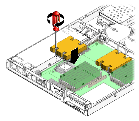
7. To install the other heatsink, repeat Step 1 through Step 6.
8. Proceed to the next section, Replacing the Firmware PROM.
To complete the hardware portion of the CPU upgrade, you need to replace the server’s firmware PROM with the new firmware PROM that is included with the kit.

|
Caution - Irreparable damage can occur to the motherboard if you do not use a PLCC extraction tool to remove the firmware PROM. A PLCC extraction tool is included in the upgrade kit. |
|
| Note - The firmware PROM is located at the rear of the server. Access to the PROM is obstructed by the PCI riser assembly. To replace the firmware PROM, you must first remove the PCI riser assembly. |
1. First, remove PCI riser assembly by gripping the ends of the assembly and lifting it straight up out of the PCI slot on the motherboard (see FIGURE 8).
| Note - If a PCI card is installed in the riser assembly, you do not need to remove the card. |
The firmware PROM is located toward the rear of the server (see FIGURE 8).
FIGURE 8 Removing the PCI Riser and Extracting the Firmware PROM
2. Set the PCI riser assembly next to the server.
3. Insert the ends of the PLCC extraction tool into the elongated corner slots on the firmware PROM socket (see FIGURE 8).
4. To remove the firmware PROM, gently squeeze the extraction tool.
This action pulls the PROM from the socket.
5. Remove the PROM from the server, and proceed to the next section.
The firmware PROM chip is keyed for proper installation in the PROM socket. The PROM chip has three right-angle corners. The fourth corner, on the beveled edge side of the firmware PROM chip, is trimmed at 45 degrees. One of the outer-edge corners of the PROM socket is trimmed the same way, and the same interior corner of the PROM socket has a semi-circular protrusion. This is the key to proper installation (see FIGURE 9). To install the firmware PROM chip properly, the trimmed corner of the chip must align with the corner of the PROM socket with the semi-circular protrusion.

|
1. Remove the new 1 Mbyte firmware PROM chip from the upgrade kit.
Handle the chip carefully. Avoid touching the metal contacts.
2. Align the trimmed corner of the PROM chip with the keyed corner of the socket.
The trimmed corner of the chip, when properly seated in the socket, must align with the socket corner that has the rounded protrusion (see FIGURE 9).
FIGURE 9 Socket and PROM Chip Alignment Key
3. When properly aligned, place the PROM chip on top of the socket.
4. Using your finger or thumb, gently push the firmware PROM chip downward into the socket until the top of the chip is flush with the top of the socket.
The new firmware PROM chip is now installed.
5. Proceed to the next section, Clearing CMOS.
After replacing the firmware PROM, you need to clear the CMOS before you update the firmware. You clear the CMOS by removing the system battery and shorting the battery terminals for 60 seconds.
|
1. Remove the system battery by pulling it up and out of the holder (see FIGURE 10).
The battery is secured in the battery holder by a metal clip that contacts the positive (‘+’) side of the battery. The opposite side of the battery, the negative side, presses against a metal contact point in the base of the battery holder. When the battery is removed the metal clip and the contact point do not touch. To clear CMOS, you must make the clip and the contact point in the battery holder touch (short) for a period of 60 seconds.
FIGURE 10 Removing System Battery and Clearing CMOS
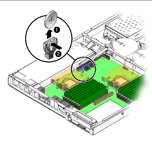
2. Press the metal clip on the battery holder inward until it touches (shorts) the metal contact point in the base of the battery holder (see FIGURE 10).
You can use your thumb and finger to press (squeeze) the clip against the contact point.
3. Continue shorting the clip and the contact point for a period of 60 seconds.
The two points must touch (short) for 60 seconds.
4. After 60 seconds, install the battery, making certain that the positive (‘+’) side of the battery faces outward (see FIGURE 10) and contacts the metal clip.
5. Install the PCI riser assembly.
6. Install the air duct, and secure it with the air duct retaining screw.
7. Proceed to the next section, Preparing for Operation.
Step |
||
|---|---|---|
1 |
||
2 |
||
3 |
||
4 |
Perform the following procedures to prepare the upgraded server for operation.
|
1. Inspect the interior of the server, ensuring that all cables are properly routed and all components are properly seated.
3. Install the server top cover.
4. Retain the kit packaging material, old heatsinks, and old CPUs.
You can return these items to Sun Microsystems.
5. Install the server in the rack, and plug in the power cable.
Before you can use the server, you must upgrade the SP and BIOS firmware. You upgrade the server firmware using the Sun Fire X2200 M2 Server Tools and Drivers CD that you created at the beginning of the upgrade procedure.
|
1. Attach a KVM to the server, so that you can view the Tools and Drivers boot menu.
2. Power on the server and insert the Tools and Drivers CD v2.0 (or later) into the server’s CD/DVD drive.
The system boots from the CD and the Tools and Drivers CD main menu appears.
A Load Defaults prompt message appears.
b. When prompted, press F2 to load defaults.
The defaults load, the server reboots, and the Tools and Drivers main menu appears.
3. From the Tools and Drivers main menu, select option #4, Exit to DOS.
4. At the DOS prompt navigate to the \flash\sp\latest directory by entering the following command:
5. At the prompt list the contents of the \flash\sp\latest directory by executing the dir command:
The contents of the directory appears.
6. Review the contents of the directory, and make note of the name of the s39uversion.bin file.
Where version is the version number of the SP firmware.
7. To update the firmware enter the following command:
C:\flash\sp\latest> download.exe -f s39uversion.bin
C:\flash\sp\latest> download.exe -f s39u315.bin
The update script verifies the PROM size before starting the update. The following warning message might appear:
If the above message appears, you do not have the 1 Mbyte PROM installed in the server. To complete the quad-core upgrade you must install the 1 Mbyte PROM that came with the Quad-Core Upgrade Kit. To replace the PROM, see Replacing the Firmware PROM.
The SP update process takes about two minutes to finish.
8. When the firmware update process ends, the server reboots.
9. Do the following depending upon the type of upgrade you are performing:
For a dual-core CPU to quad-core CPU upgrade:
For a quad-core CPU to enhanced quad-core CPU upgrade:
The firmware version preflashed onto the upgrade kit PROM chip might not be the latest version. When the server is operational verify the firmware version, and if necessary, update the PROM. During the update process the following error message appears if you are attempting to update the PROM with the wrong file:
If this message occurs during the update process, update the PROM with the correct file.
|
1. Use the ELOM web GUI or the command-line interface (CLI) to check the server’s BIOS version.
See the Sun Fire X2200 M2 Server Embedded Lights Out Manager Administrative Guide for instructions about using the web GUI or the CLI to view BIOS and SP version numbers.
2. Compare the BIOS version number of the server to the version number, that you noted in Downloading the Tools and Drivers CD.
3. If the server BIOS firmware does not match the version on the Tools and Drivers CD, use the ELOM web GUI or the CLI to update the firmware PROM.
If the version numbers match, then proceed to the next section, Performing Power On and BIOS Setup Procedures.
See the Sun Fire X2200 M2 Server Embedded Lights Out Manager Administrative Guide for instructions on updating the BIOS and SP firmware.
4. Proceed to the next section, Performing Power On and BIOS Setup Procedures.
You must access the BIOS Setup Utility and load default settings. You can then customize the BIOS settings, returning the server to the settings you retained in Recording Your Current BIOS settings.
|
1. Attach a KVM to the server, so that you can view the power-on self test (POST) messages.
2. Boot the server, and watch the POST messages as they appear on the display.
3. When prompted, press the F2 key to enter the BIOS Setup Utility.
The BIOS Setup Utility screen appears.
4. Load default settings, and Save and Exit the BIOS.
5. If you need to customize the BIOS settings, repeat Step 1 through Step 3 and enter the settings you saved in Recording Your Current BIOS settings.
6. After customizing the BIOS settings, Save and Exit the BIOS Setup Utility.
The server boots and is ready for operation.
7. Proceed to the next section, Returning Parts to Sun Microsystems.
The final step in the quad-core upgrade procedure is to return the old heatsinks and CPUs to Sun Microsystems using the SunReturns trade-in program. For information on SunReturns and trade-ins, go to:
http://www.sun.com/tradeins/sunreturns/index.jsp
|
Copyright |
Copyright 2008 Sun Microsystems, Inc., 4150 Network Circle, Santa Clara, California 95054, U.S.A. All rights reserved.
Sun Microsystems, Inc. has intellectual property rights relating to technology that is described in this document. In particular, and without limitation, these intellectual property rights may include one or more of the U.S. patents listed at http://www.sun.com/patents and one or more additional patents or pending patent applications in the U.S. and in other countries.
This document and the product to which it pertains are distributed under licenses restricting their use, copying, distribution, and decompilation. No part of the product or of this document may be reproduced in any form by any means without prior written authorization of Sun and its licensors, if any.
Third-party software, including font technology, is copyrighted and licensed from Sun suppliers.
Parts of the product may be derived from Berkeley BSD systems, licensed from the University of California. UNIX is a registered trademark in the U.S. and in other countries, exclusively licensed through X/Open Company, Ltd.
Sun, Sun Microsystems, the Sun logo, Java, Sun Fire, docs.sun.com, and Solaris are trademarks or registered trademarks of Sun Microsystems, Inc. in the U.S. and in other countries.
All SPARC trademarks are used under license and are trademarks or registered trademarks of SPARC International, Inc. in the U.S. and in other countries. Products bearing SPARC trademarks are based upon an architecture developed by Sun Microsystems, Inc.
The OPEN LOOK and Sun Graphical User Interface was developed by Sun Microsystems, Inc. for its users and licensees. Sun acknowledges the pioneering efforts of Xerox in researching and developing the concept of visual or graphical user interfaces for the computer industry. Sun holds a non-exclusive license from Xerox to the Xerox Graphical User Interface, which license also covers Sun’s licensees who implement OPEN LOOK GUIs and otherwise comply with Sun’s written license agreements.
U.S. Government Rights--Commercial use. Government users are subject to the Sun Microsystems, Inc. standard license agreement and applicable provisions of the FAR and its supplements.
DOCUMENTATION IS PROVIDED "AS IS" AND ALL EXPRESS OR IMPLIED CONDITIONS, REPRESENTATIONS AND WARRANTIES, INCLUDING ANY IMPLIED WARRANTY OF MERCHANTABILITY, FITNESS FOR A PARTICULAR PURPOSE OR NON-INFRINGEMENT, ARE DISCLAIMED, EXCEPT TO THE EXTENT THAT SUCH DISCLAIMERS ARE HELD TO BE LEGALLY INVALID.
Copyright 2008 Sun Microsystems, Inc., 4150 Network Circle, Santa Clara, Californie 95054, États-Unis. Tous droits réservés.
Sun Microsystems, Inc. possède les droits de propriété intellectuels relatifs à la technologie décrite dans ce document. En particulier, et sans limitation, ces droits de propriété intellectuels peuvent inclure un ou plusieurs des brevets américains listés sur le site http://www.sun.com/patents, un ou les plusieurs brevets supplémentaires ainsi que les demandes de brevet en attente aux les États-Unis et dans d’autres pays.
Ce document et le produit auquel il se rapporte sont protégés par un copyright et distribués sous licences, celles-ci en restreignent l’utilisation, la copie, la distribution, et la décompilation. Aucune partie de ce produit ou document ne peut être reproduite sous aucune forme, par quelque moyen que ce soit, sans l’autorisation préalable et écrite de Sun et de ses bailleurs de licence, s’il y en a.
Tout logiciel tiers, sa technologie relative aux polices de caractères, comprise, est protégé par un copyright et licencié par des fournisseurs de Sun.
Des parties de ce produit peuvent dériver des systèmes Berkeley BSD licenciés par l’Université de Californie. UNIX est une marque déposée aux États-Unis et dans d’autres pays, licenciée exclusivement par X/Open Company, Ltd.
Sun, Sun Microsystems, le logo Sun, Java, Sun Fire, docs.sun.com, et Solaris sont des marques de fabrique ou des marques déposées de Sun Microsystems, Inc. aux États-Unis et dans d’autres pays.
Toutes les marques SPARC sont utilisées sous licence et sont des marques de fabrique ou des marques déposées de SPARC International, Inc. aux États-Unis et dans d’autres pays. Les produits portant les marques SPARC sont basés sur une architecture développée par Sun Microsystems, Inc.
L’interface utilisateur graphique OPEN LOOK et Sun a été développée par Sun Microsystems, Inc. pour ses utilisateurs et licenciés. Sun reconnaît les efforts de pionniers de Xerox dans la recherche et le développement du concept des interfaces utilisateur visuelles ou graphiques pour l’industrie informatique. Sun détient une license non exclusive de Xerox sur l’interface utilisateur graphique Xerox, cette licence couvrant également les licenciés de Sun implémentant les interfaces utilisateur graphiques OPEN LOOK et se conforment en outre aux licences écrites de Sun.
LA DOCUMENTATION EST FOURNIE "EN L’ÉTAT" ET TOUTES AUTRES CONDITIONS, DÉCLARATIONS ET GARANTIES EXPRESSES OU TACITES SONT FORMELLEMENT EXCLUES DANS LA LIMITE DE LA LOI APPLICABLE, Y COMPRIS NOTAMMENT TOUTE GARANTIE IMPLICITE RELATIVE À LA QUALITÉ MARCHANDE, À L’APTITUDE À UNE UTILISATION PARTICULIÈRE OU À L’ABSENCE DE CONTREFAÇON.