Opening the Workstation
This section describes how to open and close the workstation by removing and installing the left-side access panel and the front bezel.
Do not operate the workstation for more than 10 minutes when the left-side access panel is removed. Improper cooling air flow might damage the system’s components.
 To Remove the Left-Side Access Panel
Before you remove, replace, or install any components, perform the following steps.
-
Observe the ESD procedures described in the section, Observing Electrostatic Discharge (ESD) Precautions.
-
Power off the workstation using the procedure described in section, To Power Off the Workstation.
-
Turn the power switch on the back of the chassis to the Off position (0).
 Caution –
 Failure to properly turn off the system before you start installing components can cause serious component damage.
-
To maintain system grounding, do not unplug the AC power cord from the back of the system unless the specific procedure instructs you to unplug it.
-
Power off all peripherals connected to the workstation.
-
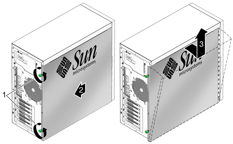
Loosen the two captive thumbscrews located on the rear edge of the left-side access panel (see Figure 3–1).
Figure 3–1 Removing the Side Access Panel

-
Slide the access panel approximately 1.5 cm toward the back of the workstation.
-
Tilt the top edge of the panel out, then lift the panel upward.
-
Set the panel aside.
 To Remove the Front Bezel
Note –
Do not remove the front bezel unless removal is required to perform a maintenance procedure.
-
Perform the steps described in the section, To Remove the Left-Side Access Panel.
-
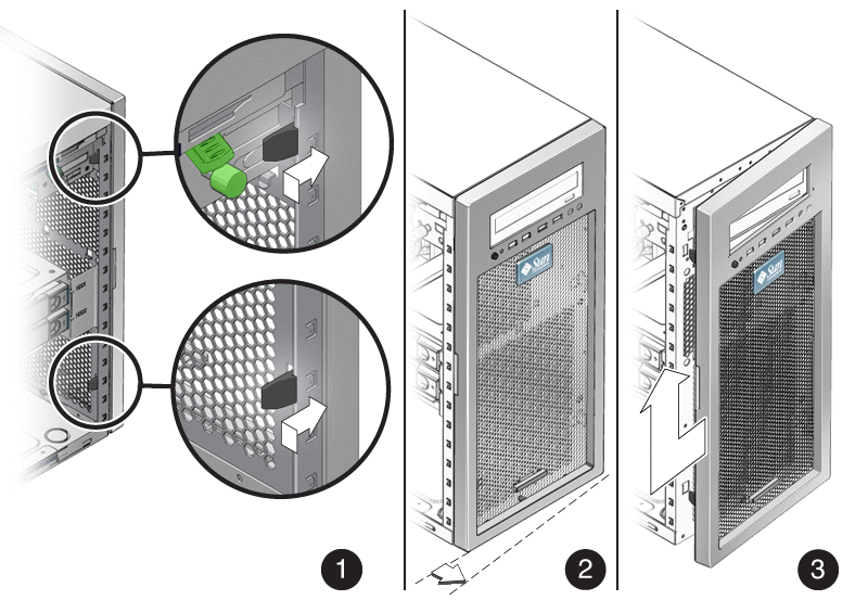
Unlatch the three left-side bezel tabs by gently pressing the side of each tab inward and slightly forward (see Figure 3–2).
The edge of the bezel nearest the tabs moves slightly away from the front of the chassis as the ridges holding each tab in place are released.
 Caution –
 The bezel tabs and the chassis hooks might break if you apply too much force or attempt to swing the bezel open. Be very careful when pulling the bezel away from the chassis.
Figure 3–2 Removing the Front Bezel

-
Gently move the bezel slightly to the left and gently pull forward to disengage the three chassis hooks on the right side.
-
Remove the bezel and set it aside.
- © 2010, Oracle Corporation and/or its affiliates
