Chapter 4 Deployment Scenarios
This chapter describes how to deploy Web Server on a single node and a cluster environment. The following topics are discussed in this chapter:
Deployment Architecture
This section describes the single node deployment architecture.
The following figure represents Web Server in a single node deployment set up.
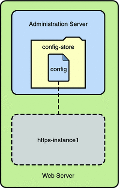
In the preceding figure, the Web Server deployment set up comprises the following components:
-
Administration Server- Administration Server is a specially configured web server instance. You can deploy web applications on the administration server.
-
Administration Node- Administration Node is deployed on a node or a server/host within a server farm and has the ability to communicate with the remote Administration Server. The server configurations available within the Administration Server can be deployed to this node. All the Administration Nodes within the server farm need to be homogeneous. That is, all the nodes must use the same operating system and have the same hardware architecture.
-
Configuration- A configuration refers to a set of all configurable elements of a Web Server instance, such as web applications, configuration files, and search collection indexes. A configuration can be created, modified, or deleted. Web Server can manage multiple configurations. Instances can be created for a configuration. Deploying a modified configuration updates the instance of that configuration.
-
config-store This is the file system-based repository where all the configurations are stored.
 Caution –
 Do not edit any file in the config-store directory. The files under this directory are created by Web Server for internal use.
If you must manually edit the configuration file in the config-store directory, deploy the configuration using the wadm deploy-config command.
For more information on using this command, see the Sun Java System Web Server 7.0 Update 8 CLI Reference Manual.
-
Instance - An instance refers to the environment of a web server on a given node, including its configuration, log files, and other runtime artifacts such as lock databases, caches, and temporary files. For management purposes, an instance can be started, stopped, restarted, or dynamically re-configured.
Deployment Overview
You can deploy Web Server on a single node for the following purposes:
-
Hosting simple web or CGI applications.
-
Developing and testing web applications.
The following flowchart provides the schematic representation of how to deploy Web Server on a single node:
Figure 4–1 Flowchart representing the deployment of web server on a single node
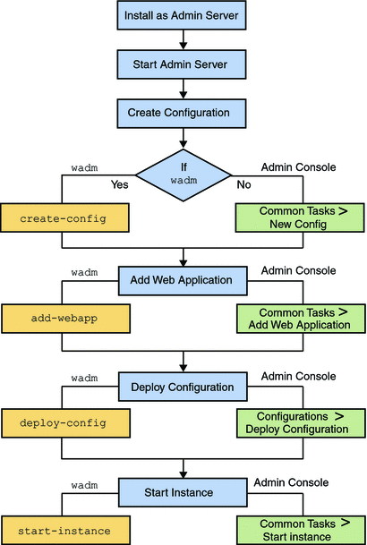
The deployment process is described in the following sections:
Pre-Deployment Requirements
To deploy the Web Server on a single node, prepare the system by performing the following tasks:
-
Install Web Server on a node.
If you choose the Express Installation option while installing Web Server, the following default entities are created:
-
An Administration Server.
-
A default configuration with one HTTP listener and a virtual server are created. The name of the configuration and the virtual server are same as the host name.
-
An instance of the default configuration.
For information on installing the Web Server, see Chapter 2, Installing the Web Server, in Sun Java System Web Server 7.0 Update 8 Installation and Migration Guide.
For information on the supported platforms and the system requirements, see Supported Platforms in Sun Java System Web Server 7.0 Update 8 Release Notes.
-
-
Start the Administration Server.
The Administration Server starts running on a specified SSL port.
Deploying Web Server
Use the following procedure to deploy Web Server on a node:
-
You can either use the default configuration or create a new configuration.
If you are creating a new configuration, specify a unique name for the configuration. The new configuration creates a virtual server and a default HTTP listener.
Note –If you are using the Administration Console to create a configuration, the wizard prompts you to create a new instance. If you are using the CLI, you must explicitly create an instance of the configuration using the create-instance command.
All the configurations are stored in the config-store directory located under <install_dir>/admin-server/ directory.
 Caution –
 Do not edit any file under the config-store directory. The files under this directory are created by Web Server for internal use.
-
Deploy the modified configuration.
Cluster Environment
A cluster is a group of multiple server instances spanning across more than one node, all running identical configurations. All instances in a cluster work together to provide high availability, reliability, and scalability.
With load balancing, a cluster offers uninterrupted service and session data persistence by providing failover and session replication.
Hardware and Software Requirements
The use case described in this section, consists of the following entities:
|
1) Four instances (running on four identical nodes) |
|
2) An Administration Server |
|
3) A reverse proxy for load balancing HTTP requests |
To set up a cluster, you need two or more identical nodes with the same operating system version and patches. For example, if you select a machine with Solaris® 9 SPARC® operating system, other machines in the cluster must also have Solaris 9 SPARC installed.
For information on supported platforms and patch requirements, see the Sun Java System Web Server 7.0 Update 8 Release Notes.
The following figure describes a clustered environment.
Figure 4–2 Cluster Set Up
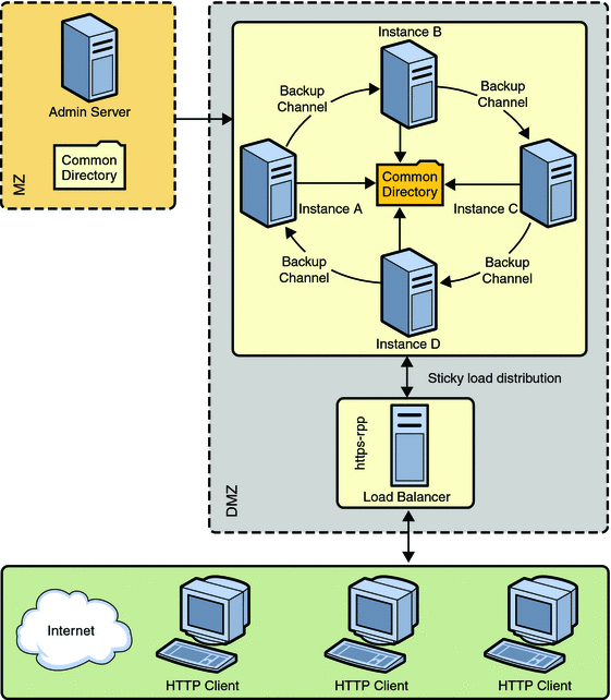
In the preceding figure, nodes are configured in the De-Militarized Zone (DMZ). The Administration Server is configured behind a firewall, the Militarized Zone, to restrict and protect the Administration Server against general access. Another node is configured as the Reverse Proxy Server. A reverse proxy server resides inside the DMZ to enhance security.
Note –
The Solaris zone feature is supported only on Solaris 10 operating system.
Setting Up a Cluster
This section describes the procedure to set up the cluster and enable reverse proxy to support load-balancing on HTTP requests.
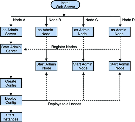
The following flowchart illustrates the procedure to set up a cluster.
Figure 4–3 Flowchart illustrating the cluster set up
-
On one of the nodes, install Web Server that acts as the Administration Server in a cluster.
-
On the other three nodes, install the Web Server. Select the option of installing Web Server as an Administration Node. During the installation, choose the option of registering the node with the server.
-
Make sure the Administration Server is using SSL port for communication, as an Administration Node can be registered with the server only in secure mode.
-
Make sure the system date and time on all the nodes where the Administration Server and the Administration Nodes are installed are the same. The certificate associated with the server is created based on the system date and time of the node where the Administration Server is installed. If the system date of the Administration Node is earlier than the Administration Server, the registration fails as the certificate of the Administration Server will not yet be valid. As a corollary, the certificate may be deemed valid if it is has expired.
-
Start the Administration Server from the install_dir/admin-server/bin/ directory.
install_dir/admin-server/bin>./startserv
-
Start the wadm command-line tool from the Administration Node. The wadm command-line tool is located in the install_dir/bin directory.
install_dir/bin>./wadm
-
Register each Administration Node with the Administration Server. Use the register-node command to register each node with the server.
For Example:
./wadm register-node -user=admin --host=abc.sfbay.sun.com --port=8989
Where,
- abc.sfbay.sun.com
-
is the host name of the Administration Server to which you are registering the Node.
- port
-
is the SSL Port number of the Administration Server.
-
You will be prompted to enter the administration password. Enter the administration password of the Administration Server.
The Administration Server authenticates by the Administration Server trusting the Administration Node's server certificate and the Administration Node trusting the client certificate presented by the Administration Server. During registration of an Administration Node, the Administration Server generates a server certificate for that Administration Node, which is then downloaded and installed on the Administration Node. The issuer of the server certificate is also installed on the Administration Node.
Note –The registration can be done only over SSL.
For information about registering nodes, see Registering the Administration Node From the Command-Line in Sun Java System Web Server 7.0 Update 8 Installation and Migration Guide.
-
Start all the Administration Nodes using the startserv command from the install_dir/admin-server/bin/ directory.
-
Using the Admin Console or the CLI, create a new configuration in the Administration Server.
Provide configuration information such as configuration name, HTTP Listener port, and the server name for the new configuration.
-
Create instances of the configuration on all the nodes.
-
Start the instances on all the nodes.
Note –Web Server provides the flexibility to expand or reduce your cluster. You can add or remove instances to the cluster at any point of time.
Configuring Reverse Proxy in Web Server 7.0
The Sun Java System Web Server 7.0 integrates the reverse proxy functionality within the core server.
When web server is configured with reverse proxy functionality, it acts as a proxy for one or more backend servers and serves as a single point of access or gateway in a server farm. In a reverse proxy setup, the web server forwards the HTTP request it received from the browser client to the appropriate backend server. The HTML response from the backend server is sent back to the browser through the web server. Thus, the web server with reverse proxy hides the existence of backend servers.
Figure 4–4 Reverse Proxy Setup
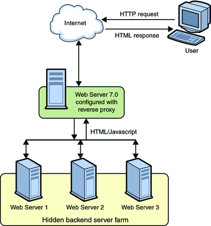
Web Server 7.0 with reverse proxy functionality acts as a simple software load balancer with the added ability to forward the sticky requests back to the same backend server.
Web server with reverse proxy can serve static content like gif and html files from its internal cache. At the same time, it functions as a load balancer and processes request for dynamic content like jsp, servlet or php files to the backend server. When web server is deployed in this configuration, disabling the Java web container will significantly reduce the memory footprint of the server. For information about disabling Java web container, see Tuning Web Container Within Web Server 7.0 in Sun Java System Web Server 7.0 Update 8 Performance Tuning, Sizing, and Scaling Guide. See CLI Reference, disable-java(1).
The advantages of reverse proxy within Web Server 7.0 are:
-
Conditional processing of request to the backend servers using the integrated regular expression support. For example, you can configure web server to function as reverse proxy only for Servlet and JSP. See Customizing Reverse Proxy.
-
Ability to efficiently edit the response received from the backend server using sed-response filter before sending the response. For information about sed-response, see sed-response in Sun Java System Web Server 7.0 Update 8 Administrator’s Configuration File Reference.
-
Ability to dynamically scale the web site by adding more backend servers with less configuration changes and minimal downtime. To add an additional backend server, you should edit the virtual server specific obj.conf and run the reconfig command. For information about reconfig command, see Dynamic Reconfiguration in Sun Java System Web Server 7.0 Update 8 Administrator’s Configuration File Reference.
Note –
In a typical deployment, one or more reverse proxies will be deployed between the browsers and the backend servers.
Configuring Reverse Proxy for Load-balancing
Web Server 7.0 provides a sophisticated built-in load balancer, the reverse proxy, which distributes load or request from the client to several backend servers.
Web Server provides GUI and CLI support for configuring the reverse proxy.
 Configuring Reverse Proxy Using Administration
Console
-
Install Web Server on the node that you want to use for configuring reverse proxy.
-
Create a configuration. For example, rp.
-
Using the Administration Console, select Configurations > Virtual Servers > Content Handling > Reverse Proxy tab. Click New.
-
Specify values for the following parameters:
-
URI — The reverse proxy URI
-
Server URL — Comma separated server URLs of all the machines in the cluster separated by comma. If multiple values are given, the server will distribute load among the specified servers.
The format for entering the server URL is hostname:portnumber. For example, http://<content server-hostname>:port
-
-
Click the OK button.
-
Click the Deployment Pending link in the top right of the screen to deploy the modified configuration and to apply changes to the configuration.
-
Click the Deploy button.
Deployment successful message appears.
-
Start all instances of this modified configuration.
This completes configuring the reverse proxy for load balancing HTTP requests.
Note –To configure a reverse proxy in a cluster environment, issue a wildcard server certificate or the alternate subject names that can be set to the actual origin server host names. The other option of specifying the original server's host names in the subject name field limits the size of the cluster, leading the cluster to fail if another node is added to the cluster.
A wildcard server certificate can be created using the administration interfaces. After creating the server certificate use certutil to get the base64 encoded version of the certificate and install it as a trusted CA certificate on the load balancer configuration.
Type the following command to generate the base64 encoded certificate bash$./certutil -L -a -d instancedir/config. Copy the output of the command and paste it in the install certificate wizard.
 Configuring Reverse Proxy Using CLI
Perform the following steps to configure reverse proxy in CLI mode. You will create a configuration config1 and an instance rp as reverse proxy.
-
Start the Administration Server:
$ <install-dir>/admin-server/bin/startserv
-
Invoke the CLI shell:
<install-dir>/admin-server/bin/wadm -user <username>
You can see the wadm shell
-
Create config1:
wadm>create-config --http-port=8080 --server-name=config1 --server-user=root config1
-
Create an instance for the config1 configuration:
wadm>create-instance --config=config1 <host-name>
-
Add the web application on the created configuration:
wadm>add-webapp --config=config1 -vs=config1 --uri/test <warfile>
-
Deploy the web application.
wadm>deploy-config --user=admin --password-file=admin.pwd --host=serverhost --port=8989 config1
-
Create a rp configuration:
wadm>create-config --http-port=8081 --server-name=rp --server-user=root rp
-
Enable the rp configuration to reverse proxy using the following command:
wadm> create-reverse-proxy --user=admin --password-file=admin.pwd
--host=serverhost --config=rp --vs=rp --uri-prefix=//
--server=http://rick.india.sun.com:8080
To redirect to a secure site, follow the same step and provide the
httpsaddress for the--serveroption.See CLI Reference, create-reverse-proxy(1).
-
Create an instance for the rp configuration.
wadm>create-instance --config=rp <host-name>
-
Start the instances:
wadm>start-instance --config=config1 <host-name>
wadm>start-instance --config=rp <hostname>
The web application deployed in config1 can be viewed through rp instance.
http://<rp instance hostname>:8081/test
See CLI Reference, list-reverse-proxy-uris(1), set-reverse-proxy-prop(1), get-reverse-proxy-prop(1), forward-reverse-proxy-header(1), block-reverse-proxy-header(1), and list-reverse-proxy-headers(1)
Modifying Reverse Proxy Parameters
 To Modify Reverse Proxy Parameters
-
Using the Administration Console, select Configurations > Virtual Servers > Content Handling > Reverse Proxy tab.
-
Click the URI button.
You can edit the following parameters:
-
URI — The reverse proxy URI
-
Server URL — Comma separated URLs of the remote server. If multiple values are given, the server will distribute load among the specified servers.
-
Sticky Cookie — Name of a cookie that when present in a response, will cause subsequent requests to stick to that origin server.
-
Sticky URI Parameter — Name of a URI parameter to inspect for route information. When the URI parameter is present in a request URI and its value contains a colon `:' followed by a route ID, the request will "stick" to the origin server identified by that route ID.
-
Route Header — Name of the HTTP request header used to communicate route IDs to origin servers.
-
Route Cookie — Name of the cookie generated by the server when it encounters a sticky cookie in a response. The route cookie stores a route ID that enables the server to direct subsequent requests back to the same origin server.
-
Rewrite Headers — Comma separated list of HTTP request headers.
-
Configuring Timeout Parameter in Reverse Proxy
-
Using the Administration Console, select Configurations > Virtual Servers > Content Handling > Reverse Proxy tab.
-
Click the URI button.
A new window appears.
-
Click the HTTP Client Configuration link.
You can edit the Idle Timeout parameter. The default value is 300.
Customizing Reverse Proxy
You can configure conditional request processing in reverse proxy by manually editing the virtual server specific obj.conf file or through CLI. After the configuration changes are done, it is recommended to deploy the configuration and start the instance so that the changes are implemented.
wadm>deploy-config config_name |
wadm>start-instance --config config_name hostname |
See CLI Reference, deploy-config(1), start-instance(1)
Note –
The appropriate obj.conf file used by your virtual server should be modified. It can be <vs>-obj.conf or the default obj.conf, depending on the configuration.
The following examples discuss some of the possible configurations in Web Server.
-
Configuring reverse proxy for all .jsp, .php requests.
-
Create a rp configuration.
wadm>create-config --http-port=8081 --server-name=rp --server-user=root rp
-
Enable the rp configuration to reverse proxy using the following command:
wadm> create-reverse-proxy --user=admin --password-file=admin.pwd
--host=serverhost --config=rp --vs=rp --uri-prefix=//
--server=http://rick.india.sun.com:8080
-
Disable Java for the rp configuration.
wadm disable-java --user=admin --password-file=admin.pwd
--host=serverhost --config=rp
See CLI Reference, disable-java(1).
-
Create an instance for the rp configuration.
wadm>create-instance --config=rp <host-name>
-
Modify the
<vs>-obj.conffile, so that the above expression is added to the NameTrans fn="map" directive.
NameTrans fn="map" from="/" to="http:/" name="custom_reverse_proxy"
...
<Object name ="custom_reverse_proxy">
Route fn="set-origin-server" server="http://<hostname>:<port>"
</Object>

<Object name ppath="http:*"
Service fn="proxy-retrieve" method="*"
</Object>
-
-
Configuring http-referer header in reverse proxy.
-
Create a rp configuration.
wadm>create-config --http-port=8081 --server-name=rp --server-user=root rp
-
Enable the rp configuration to reverse proxy using the following command:
wadm> create-reverse-proxy --user=admin --password-file=admin.pwd
--host=serverhost --config=rp --vs=rp --uri-prefix=/ilearn
--server=http://rick.india.sun.com:8080
-
Create an instance for the rp configuration.
wadm>create-instance --config=rp <host-name>
-
Modify the
<vs>-obj.conffile, so that the above expression is added to the NameTrans fn="map" directive.
<Object name="reverse-proxy-/ilearn">
NameTrans fn="set-variable"
$headers{'Referer'}="http://learning.sun.com/TOI/LEARN.html"
Route fn="set-origin-server" server="http://spb-sls-dev.russia.sun.com:7777"
</Object>
-
-
Setting up a simple failover scenario for the reverse proxy functionality.
For example, in a setup there are two reverse proxies which proxy to two separate web servers without load balancing. There is a one to one relationship in a normal scenario. However, if one backend server is down the reverse proxy should send request to the other live web server. Modify the obj.conf file as shown below.
<Object name="default">

<If $path  =~ '/servlet' or $path =~ '\.jsp'>
<If  not $restarted>
NameTrans fn="map" name="reverse-proxy"  from="/" to="http:"
</If>
<If $restarted>
NameTrans fn="map" name="reverse-proxy-alt"  from="/" to="http:"
</If>
</If>

</Object>

<Object name="reverse-proxy">
Route fn="set-origin-server" server="<back-end-server>"
# If back end server is not available, restart the request
<If $code =~ 504>
Error fn="restart" uri="$uri"
</If>
</Object>

<Object name="reverse-proxy-alt">
Route fn="set-origin-server" server="<alternate-back-end-server>"
</Object>

<Object ppath="http:*">
Service fn="proxy-retrieve" method="*"
</Object>
For every request, the server will first try to reach the first backend server. When this is not available, the request will be sent to the failover server or alternate backend server.
-
Setting up a software load balancer to two web server instances that host dynamic content.
Add server names in the server parameter, separated by a comma (,) and execute the command through CLI.
wadm> create-reverse-proxy --user=admin --password-file=admin.pwd
--host=serverhost --config=rp --vs=rp --uri-prefix=//
--servers=hostname:port,hostname1:port
-
Configuring timeout value for reverse proxy.
The Web Server 7.0 configured with reverse proxy, returns a gateway timeout error as the backend server takes a long time to respond. You can set the timeout value through CLI as below:
wadm> set-reverse-proxy-prop --user=admin --password-file=admin.pwd
--host=serverhost --config=rp --vs=rp--uri-prefix=//
--server=http://rick.india.sun.com:8080 timeout=400
See CLI reference, set-reverse-proxy-prop(1).
The default timeout value is 300 seconds. Once the response timeout value is defined, if the connection hangs for more than 400 seconds, the reverse proxy identifies the backend instance offline and closes the connection.
Session Replication
Session replication is a mechanism used to replicate the data stored in a session across different instances. However, the replicated instance must be part of the same cluster. When session replication is enabled in a cluster environment, the entire session data is copied on a replicated instance. However, the session replication operation does not copy the attributes that cannot be serialized in a session and any instance specific data.
Session replication along with load balancing provides good failover capabilities for web applications.
Note –
Before using Session Replication and Failover features, it is necessary to synchronize machine times of all machines in a cluster over which Web Server nodes are installed. This time synchronization needs to done using some utility such as ntpdate on Solaris, and not manually.
Session Replication and Failover Operation
This section describes the session replication operation in detail.
At the end of a web request, the Web Server determines whether the session data needs to be copied through the session replication configuration that is stored in the server configuration file, the server.xml.
Consider a use case of four instances forming a cluster with session replication enabled on the Administration Server.
The session replication process in a Web Server cluster of four instances (A, B, C, and D) running on four nodes is as follows:
-
Instance A is backup of D, B is backup of A, C is backup of B, and D is backup of C. This forms a complete backup ring.
-
Each instance in the cluster keeps track of a static list of all the instances in the cluster and an active backup instance.
-
Depending on the configuration, session data is sent to the backup instance synchronously at the end of each request.
The failover process in a Web Server clustered environmentis as follows:
-
The load balancer redirects all incoming web requests destined for instance A to the remaining instances in the cluster and the backup ring is re-configured as follows:
-
D detects that its backup A is down and selects the next instance to A on the ordered list as its new backup instance.
-
B is selected and D establishes a new backup connection to B. B now holds two backups: a read-only backup of A and an active backup of D.
The backup ring is now complete with B backing up to C, C backing up to D, and D backing up to B.
-
When the failed instance A is made available again, it rejoins the backup ring by sending its designated backup instance B a rejoin message and establishes a backup connection to B.
-
When D detects that Ais online by either receiving a successful ping return from A or by receiving a message from A, D then establishes a backup connection to A and terminates its backup connection to B.
-
Web Server 7.0 does not support the following features in session replication:
-
Recovering the simultaneous failures of two or more instances.
-
The interval between two failures must be greater than the time needed for a resurrected instance to fully recover.
-
Session backup to more than one instance. In normal operation, there are only two copies of any session: the primary session and a backup session.
-
Session persistence: Sessions are only backed up in memory of another instance for the purpose of failover
-
Web Server supports session replication for only Java web applications. If you are using non-Java applications such as CGI or PHP, the session data cannot be replicated.
Enabling Session Replication
You can enable session replication in a cluster using either the Admin Console or the CLI. Before you enable session replication, make sure that your browser is cookie enabled.
The server.xml file contains the information related to session replication. A sample server.xml file with session replication enabled is given below:
<cluster>
		<local-host>hostA</local-host>
			<instance>
         <host>hostB</host>
      </instance>
      <instance>
          <host>hostC</host>
      </instance>
       <instance>
          <host>hostD</host>
      </instance>
      <instance>
           <host>hostA</host>
    <session-replication/>
</cluster>
If you are using the default values for the following elements, the entry for these elements will not be available in the server.xml configuration file:
|
Port number (default is 1099) |
|
Protocol (default is jrmp) |
|
Encrypted (default is false) |
|
Getattribute Triggers Replication (default is true) |
|
Replica Discovery MaxHops (default is –1) |
|
Startup Discovery Timeout (default is 0. Relies on Java API to get system timimg. In non Unix based operating systems, it may not be accurate.) |
|
Cookie Name (default is CLUSTERSESSIONLOCATOR) |
For more information about these session replication properties, see the Sun Java System Web Server 7.0 Update 8 Administrator’s Configuration File Reference.
Configuring a Web Application for Session Replication
To enable the server to replicate the session, the web application must also be enabled for session replication.
-
To enable session replication for a web application, modify the sun-web.xml configuration file located in the <web-application>/WEB-INF directory.
The modification needed in the sunweb.xml is as follows:
Change the element <session-manager/> to <session-manager persistence-type="replicated">
The sample sun-web.xml file with session replication enabled is given below:
<sun-web-app> <session-config> <session-manager persistence-type="replicated"> </session-manager> </session-config> </sun-web-app> -
After modifying the sunweb.xml file, either rebuild the web application or re-jar the application to create a web application archive (a war file).
-
Restart all the instances to make the web application available on all the instances.
-
The web application is accessible from all the nodes in the cluster. To access the web application, in a browser, type the following:
http://webserver-name/webapplication-name/
Note –A directory that is accessible to all nodes is the best way to store the applications for deployment. This directory, however, need not be accessible to the Administration Server. It is recommended to make directory-based deployments of web applications that are more than 1 MB in size.
To create search collections, ensure that the search collection resides in a common directory that is accessible to all the nodes.
Monitoring a Cluster
The Administration Server can monitor all the instances in a cluster. The monitoring feature in Web Server provides information on the state of runtime components and processes that can be used to:
-
Identify performance bottlenecks
-
Tune the system for optimal performance
-
Aid capacity planning
-
Predict failures
-
Perform root cause analysis in case of failures
Solaris Zones
Solaris Zones are an application and resource management feature of Solaris 10. A zone environment typically consists of resources such as process management, memory, network configuration, file systems, package registries, user accounts, shared libraries, and in some cases, installed applications. Zones provide a means of creating virtualized operating system environments within an instance of Solaris, allowing one or more processes to run in isolation from other activity on the system. They also provide an abstraction layer that separates applications from physical attributes of the machine on which they are deployed, such as physical device paths and network interface names, and network routing tables. This isolation prevents processes running within a given zone from monitoring or affecting processes running in other zones, regardless of user ID and other credential information.
A zone is a sandbox within which one or more applications can run without affecting or interacting with the rest of the system.
For detailed information about Solaris Zones, see the System Administration Guide — Solaris Containers-Resource Management and Solaris Zones at http://docs.sun.com/app/docs/doc/817-1592.
- © 2010, Oracle Corporation and/or its affiliates
