|
0
|
FRU 0 HOT_SWAP
|
Discrete (0x6f), "Hot Swap" (0xf0)
|
Hot swap for Active ShMM
|
|
|
2
|
FRU 1 HOT_SWAP
|
Discrete (0x6f), "Hot Swap" (0xf0)
|
Hotswap RTM.
|
N/A
|
|
3
|
FRU 2 HOT_SWAP
|
Discrete (0x6f), "Hot Swap" (0xf0)
|
Hotswap for Shelf EEPROM (redundant PROM).
|
|
|
4
|
FRU 8 HOT_SWAP
|
Discrete (0x6f), "Hot Swap" (0xf0)
|
Hot swap for SAP
|
|
|
5
|
FRU 3 HOT_SWAP
|
Discrete (0x6f), "Hot Swap" (0xf0)
|
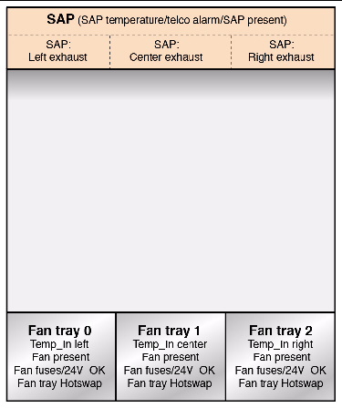
Hot swap for Fan Tray 0
|
|
|
6
|
FRU 4 HOT_SWAP
|
Discrete (0x6f), "Hot Swap" (0xf0)
|
Hot swap for Fan Tray 1
|
|
|
7
|
FRU 5 HOT_SWAP
|
Discrete (0x6f), "Hot Swap" (0xf0)
|
Hot swap for Fan Tray 2
|
|
|
8
|
FRU 6 HOT_SWAP
|
Discrete (0x6f), "Hot Swap" (0xf0)
|
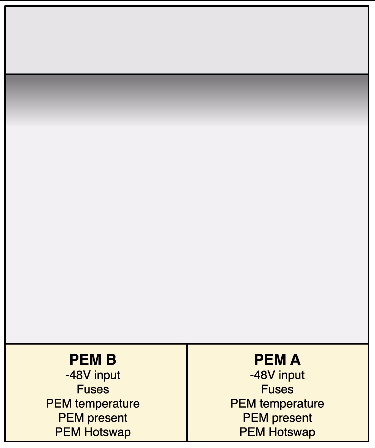
Hot swap for PEM A
|
|
|
9
|
FRU 7 HOT_SWAP
|
Discrete (0x6f), "Hot Swap" (0xf0)
|
Hot swap for PEM B
|
|
|
10
|
IPMB LINK 1
|
Discrete (0x6f), "IPMB Link" (0xf1)
|
IPMI bus to slot 7 (address 41h). Redundant pair (IPMB_A and IPMB_B)
|
If both the IPMB-A and IPMB links are disabled the shelf manager will not communicate with the blade in slot 7.
|
|
11
|
IPMB LINK 2
|
Discrete (0x6f), "IPMB Link" (0xf1)
|
IPMI bus to slot 8 (address 42h). Redundant pair (IPMB_A and IPMB_B)
|
If both the IPMB-A and IPMB links are disabled the shelf manager will not communicate with the blade in slot 8.
|
|
12
|
Fan Tray 0
|
Discrete (0x6f), "Entity Presence" (0x25)
|
Fan tray 0 present.
|
Lack of fan tray compromises thermal integrity. All Fan trays must be installed.
|
|
13
|
Fan Tray 1
|
Discrete (0x6f), "Entity Presence" (0x25)
|
Fan tray 1 present.
|
Lack of fan tray compromises thermal integrity. All Fan trays must be installed.
|
|
14
|
Fan Tray 2
|
Discrete (0x6f), "Entity Presence" (0x25)
|
Fan tray 2 present.
|
Lack of fan tray compromises thermal integrity. All Fan trays must be installed.
|
|
15
|
IPMB LINK 3
|
Discrete (0x6f), "IPMB Link" (0xf1)
|
IPMI bus to slot 6 (address 43h). Redundant pair (IPMB_A and IPMB_B)
|
If both the IPMB-A and IPMB links are disabled the shelf manager will not communicate with the blade in slot 6.
|
|
16
|
IPMB LINK 4
|
Discrete (0x6f), "IPMB Link" (0xf1)
|
IPMI bus to slot 9 (address 44h). Redundant pair (IPMB_A and IPMB_B)
|
If both the IPMB-A and IPMB links are disabled the shelf manager will not communicate with the blade in slot 9.
|
|
17
|
IPMB LINK 5
|
Discrete (0x6f), "IPMB Link" (0xf1)
|
IPMI bus to slot 5 (address 45h). Redundant pair (IPMB_A and IPMB_B)
|
If both the IPMB-A and IPMB links are disabled the shelf manager will not communicate with the blade in slot 5.
|
|
18
|
IPMB LINK 6
|
Discrete (0x6f), "IPMB Link" (0xf1)
|
IPMI bus to slot 10 (address 46h). Redundant pair (IPMB_A and IPMB_B)
|
If both the IPMB-A and IPMB links are disabled the shelf manager will not communicate with the blade in slot 10.
|
|
19
|
IPMB LINK 7
|
Discrete (0x6f), "IPMB Link" (0xf1)
|
IPMI bus to slot 4 (address 47h). Redundant pair (IPMB_A and IPMB_B)
|
If both the IPMB-A and IPMB links are disabled the shelf manager will not communicate with the blade in slot 4.
|
|
20
|
IPMB LINK 8
|
Discrete (0x6f), "IPMB Link" (0xf1)
|
IPMI bus to slot 11 (address 48h). Redundant pair (IPMB_A and IPMB_B)
|
If both the IPMB-A and IPMB links are disabled the shelf manager will not communicate with the blade in slot 11.
|
|
21
|
IPMB LINK 9
|
Discrete (0x6f), "IPMB Link" (0xf1)
|
IPMI bus to slot 3 (address 49h). Redundant pair (IPMB_A and IPMB_B)
|
If both the IPMB-A and IPMB links are disabled the shelf manager will not communicate with the blade in slot 3.
|
|
22
|
IPMB LINK 10
|
Discrete (0x6f), "IPMB Link" (0xf1)
|
IPMI bus to slot 12 (address 4Ah). Redundant pair (IPMB_A and IPMB_B)
|
If both the IPMB-A and IPMB links are disabled the shelf manager will not communicate with the blade in slot 12.
|
|
23
|
IPMB LINK 11
|
Discrete (0x6f), "IPMB Link" (0xf1)
|
IPMI bus to slot 2 (address 4Bh). Redundant pair (IPMB_A and IPMB_B)
|
If both the IPMB-A and IPMB links are disabled the shelf manager will not communicate with the blade in slot 2.
|
|
24
|
IPMB LINK 12
|
Discrete (0x6f), "IPMB Link" (0xf1)
|
IPMI bus to slot 13 (address 4Ch). Redundant pair (IPMB_A and IPMB_B)
|
If both the IPMB-A and IPMB links are disabled the shelf manager will not communicate with the blade in slot 13.
|
|
25
|
IPMB LINK 13
|
Discrete (0x6f), "IPMB Link" (0xf1)
|
IPMI bus to slot 1 (address 4Dh). Redundant pair (IPMB_A and IPMB_B)
|
If both the IPMB-A and IPMB links are disabled the shelf manager will not communicate with the blade in slot 1.
|
|
26
|
IPMB LINK 14
|
Discrete (0x6f), "IPMB Link" (0xf1)
|
IPMI bus to slot 14 (address 4Eh). Redundant pair (IPMB_A and IPMB_B)
|
If both the IPMB-A and IPMB links are disabled the shelf manager will not communicate with the blade in slot 14.
|
|
27
|
IPMB LINK 15
|
Discrete (0x6f), "IPMB Link" (0xf1)
|
IPMI Backplane
|
|
|
120
|
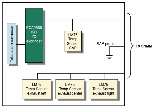
Center Exhaust
|
Threshold (0x01), "Temperature" (0x01)
|
Exhaust air temperature, Center
|
If the exhaust air temperature goes above the UNR threshold the blades may overheat.
|
|
121
|
Left Exhaust
|
Threshold (0x01), "Temperature" (0x01)
|
Exhaust air temperature, Left
|
If the exhaust air temperature goes above the UNR threshold the blades may overheat.
|
|
122
|
Right Exhaust
|
Threshold (0x01), "Temperature" (0x01)
|
Exhaust air temperature, Right
|
If the exhaust air temperature goes above the UNR threshold the blades may overheat.
|
|
123
|
SAP Temp
|
Threshold (0x01), "Temperature" (0x01)
|
Temperature sensor on SAP board
|
If the SAP air temperature goes above the UNR threshold the blades may overheat.
|
|
124
|
Temp_In Left
|
Threshold (0x01), "Temperature" (0x01)
|
Temperature of inlet air Left, Located in fan tray
|
If the intake air temperature goes above the UNR threshold the computer room airconditioning has failed.
|
|
125
|
Temp_In Center
|
Threshold (0x01), "Temperature" (0x01)
|
Temperature of inlet air Center, Located in fan tray
|
If the intake air temperature goes above the UNR threshold the computer room airconditioning has failed.
|
|
126
|
Temp_In Right
|
Threshold (0x01), "Temperature" (0x01)
|
Temperature of inlet air Right, Located in fan tray
|
If the intake air temperature goes above the UNR threshold the computer room airconditioning has failed.
|
|
131
|
TELCO Alarms
|
Discrete (0x6f), "OEM reserved" (0xdf)
|
Telco event occurred.
|
|
|
132
|
BMC Watchdog
|
Discrete (0x6f), "Watchdog 2" (0x23)
|
ATCA IPMI watchdog.
|
|
|
133
|
SYSTEM EVENT
|
Discrete (0x6f), "System Event" (0x12)
|
System reconfiguration event.
|
|
|
135
|
FT Oper. Status
|
Management
Subsystem
Health (28h)
|
Current cooling state of the shelf:
- 00h = Full Redundancy = all fan trays defined in the Address Table are operational
- 01h = Redundancy Lost = some of the fan trays defined in the Address Table are missing or nonoperational.
With the HPDL default cooling management strategy, this causes the fan level for all remaining fan trays to be set to their maximum.
|
|
|
136
|
Cooling State
|
Management
Subsystem
Health (28h)
|
00h = transition to OK. The cooling state is Normal
- 01h transition to Non-Critical from OK. The cooling state is now Minor Alert, the previous cooling state was Normal.
- 02h transition to Critical from less severe. The cooling state is now Major Alert, the previous cooling state was either Normal or Minor Alert.
- 04h transition to Non-Critical from more severe. The cooling state is now Minor Alert, the previous cooling state was either Major or Critical Alert.
- 05h transition to Critical from Non-recoverable. The current cooling state is Major Alert, the previous cooling state was Critical Alert.
- 06h transition to Nonrecoverable. The current cooling state is now Critical Alert.
|
|
|
137
|
Fans State
|
Management
Subsystem
Health (28h)
|
- 00h = transition to OK. The fans state is Normal (no thresholds are crossed on fan tachometer sensors).
- 01h = transition to Non-Critical from OK. The fans state is now Minor Alert (non-critical thresholds are crossed for some tachometer.
|
|
|
150
|
Air Filter
|
Discrete (0x6f), "Entity Presence" (0x25)
|
Air filter presence sensor.
|
If the air filter is not present the blades will get dirty and may overheat.
|
|
152
|
SAP
|
Discrete (0x6f), "Entity Presence" (0x25)
|
SAP presence.
|
With no SAP, there will be no Telco alarms. SAP temperature and exhaust temperatures not available with SAP missing.
|
|
162
|
PEM A In 2
|
Discrete (0x6f), "Entity Presence" (0x25)
|
PEM A input 2, before fuse.
|
If failed, FRUs powered by input 2 will not have power redundancy.
|
|
163
|
PEM A In 2 Fused
|
Discrete (0x6f), "Entity Presence" (0x25)
|
PEM A input 2, after fuse.
|
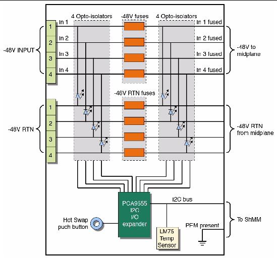
Sensor #162 and 163 can be used to determine if fuse is failed or if input is not connected. See Table 2.
|
|
164
|
PEM A In 1
|
Discrete (0x6f), "Entity Presence" (0x25)
|
PEM A input 1, before fuse.
|
If failed, FRUs powered by input 1 will not have power redundancy.
|
|
165
|
PEM A In 1 Fused
|
Discrete (0x6f), "Entity Presence" (0x25)
|
PEM A input 1, after fuse.
|
Sensor #164 and 165 can be used to determine if fuse is failed or if input is not connected. See Table 2.
|
|
166
|
PEM A In 4
|
Discrete (0x6f), "Entity Presence" (0x25)
|
PEM A input 4, before fuse.
|
If failed, FRUs powered by input 4 will not have power redundancy.
|
|
167
|
PEM A In 4 Fused
|
Discrete (0x6f), "Entity Presence" (0x25)
|
PEM A input 4, after fuse.
|
Sensor #166 and 167 can be used to determine if fuse is failed or if input is not connected. See Table 2.
|
|
168
|
PEM A In 3
|
Discrete (0x6f), "Entity Presence" (0x25)
|
PEM A input 3, before fuse.
|
If failed, FRUs powered by input 3 will not have power redundancy.
|
|
169
|
PEM A In 3 Fused
|
Discrete (0x6f), "Entity Presence" (0x25)
|
PEM A input 3, after fuse.
|
Sensor #168 and 169 can be used to determine if fuse is failed or if input is not connected. See Table 2.
|
|
174
|
PEM B In 2
|
Discrete (0x6f), "Entity Presence" (0x25)
|
PEM B input 2, before fuse.
|
If failed, FRUs powered by input 2 will not have power redundancy.
|
|
175
|
PEM B In 2 Fused
|
Discrete (0x6f), "Entity Presence" (0x25)
|
PEM B input 2, after fuse.
|
Sensor #174 and 175 can be used to determine if fuse is failed or if input is not connected. See Table 2.
|
|
176
|
PEM B In 1
|
Discrete (0x6f), "Entity Presence" (0x25)
|
PEM B input 1, before fuse.
|
If failed, FRUs powered by input 1 will not have power redundancy.
|
|
177
|
PEM B In 1 Fused
|
Discrete (0x6f), "Entity Presence" (0x25)
|
PEM B input 1, after fuse.
|
Sensor #176 and 177 can be used to determine if fuse is failed or if input is not connected. See Table 2.
|
|
178
|
PEM B In 4
|
Discrete (0x6f), "Entity Presence" (0x25)
|
PEM B input 4, before fuse.
|
If failed, FRUs powered by input 4 will not have power redundancy.
|
|
179
|
PEM B In 4 Fused
|
Discrete (0x6f), "Entity Presence" (0x25)
|
PEM B input 4, after fuse.
|
Sensor #178 and 179 can be used to determine if fuse is failed or if input is not connected. See Table 2.
|
|
180
|
PEM B In 3
|
Discrete (0x6f), "Entity Presence" (0x25)
|
PEM B input 3, before fuse.
|
If failed, FRUs powered by input 3 will not have power redundancy.
|
|
181
|
PEM B In 3 Fused
|
Discrete (0x6f), "Entity Presence" (0x25)
|
PEM B input 3, after fuse.
|
Sensor #180 and 181 can be used to determine if fuse is failed or if input is not connected. See Table 2.
|
|
192
|
PEM A
|
Discrete (0x6f), "Entity Presence" (0x25)
|
PEM A present.
|
If no PEM A, then PEM B will power up system.
|
|
193
|
PEM B
|
Discrete (0x6f), "Entity Presence" (0x25)
|
PEM B present.
|
If no PEM B, then PEM A will power up system.
|
|
194
|
Shelf EEPROM 1
|
Discrete (0x6f), "Entity Presence" (0x25)
|
|
|
|
195
|
Shelf EEPROM 2
|
Discrete (0x6f), "Entity Presence" (0x25)
|
|
|
|
200
|
PEM A Temp
|
Threshold (0x01), "Temperature" (0x01)
|
Temperature in PEM A
|
If the PEM temperature goes above the UNR threshold there is a cooling problem.
|
|
201
|
PEM B Temp
|
Threshold (0x01), "Temperature" (0x01)
|
Temperature in PEM B
|
If the PEM temperature goes above the UNR threshold there is a cooling problem.
|
|
208
|
24V FT 0
|
Discrete (0x6f), "Entity Presence" (0x25)
|
Output of 24V DC-DC converter OK
|
If the 24V DC-DC fails, fans in FT0 will fail
|
|
209
|
-48A bus FT 0
|
Discrete (0x6f), "Entity Presence" (0x25)
|
FT 0 A input, before fuse
|
If both A and B feeds are missing then the 24V DC-DC converter will not operate.
|
|
210
|
-48A FT 0
|
Discrete (0x6f), "Entity Presence" (0x25)
|
FT 0 A input, after fuse
|
If both A and B feeds are missing then the 24V DC-DC converter will not operate.
|
|
211
|
-48B bus FT 0
|
Discrete (0x6f), "Entity Presence" (0x25)
|
FT 0 B input, before fuse
|
If both A and B feeds are missing then the 24V DC-DC converter will not operate.
|
|
212
|
-48B FT 0
|
Discrete (0x6f), "Entity Presence" (0x25)
|
FT 0 B input, after fuse
|
If both A and B feeds are missing then the 24V DC-DC converter will not operate.
|
|
213
|
-48A FT 0 Fuse
|
Discrete (0x6f), "Entity Presence" (0x25)
|
FT 0 A input fuse
|
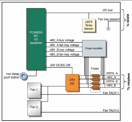
Sensor #209 and 210 are used to determine if fuse has failed or if input is not present.
|
|
214
|
-48B FT 0 Fuse
|
Discrete (0x6f), "Entity Presence" (0x25)
|
FT 0 B input fuse
|
Sensor #211 and 212 are used to determine if fuse has failed or if input is not present.
|
|
215
|
24V FT 1
|
Discrete (0x6f), "Entity Presence" (0x25)
|
Output of 24V DC-DC converter OK
|
If the 24V DC-DC fails, fans in FT1 will fail
|
|
216
|
-48A bus FT 1
|
Discrete (0x6f), "Entity Presence" (0x25)
|
FT 1 A input, before fuse
|
If both A and B feeds are missing then the 24V DC-DC converter will not operate.
|
|
217
|
-48A FT 1
|
Discrete (0x6f), "Entity Presence" (0x25)
|
FT 1 A input, after fuse
|
If both A and B feeds are missing then the 24V DC-DC converter will not operate.
|
|
218
|
-48B bus FT 1
|
Discrete (0x6f), "Entity Presence" (0x25)
|
FT 1 B input, before fuse
|
If both A and B feeds are missing then the 24V DC-DC converter will not operate.
|
|
219
|
-48B FT 1
|
Discrete (0x6f), "Entity Presence" (0x25)
|
FT 1 B input, after fuse
|
If both A and B feeds are missing then the 24V DC-DC converter will not operate.
|
|
220
|
-48A FT 1 Fuse
|
Discrete (0x6f), "Entity Presence" (0x25)
|
FT 1 A input fuse
|
Sensor #209 and 210 are used to determine if fuse has failed or if input is not present.
|
|
221
|
-48B FT 1 Fuse
|
Discrete (0x6f), "Entity Presence" (0x25)
|
FT 1 B input fuse
|
Sensor #211 and 212 are used to determine if fuse has failed or if input is not present.
|
|
222
|
24V FT 2
|
Discrete (0x6f), "Entity Presence" (0x25)
|
Output of 24V DC-DC converter OK
|
If the 24V DC-DC fails, fans in FT2 will fail
|
|
223
|
-48A bus FT 2
|
Discrete (0x6f), "Entity Presence" (0x25)
|
FT 2 A input, before fuse
|
If both A and B feeds are missing then the 24V DC-DC converter will not operate.
|
|
224
|
-48A FT 2
|
Discrete (0x6f), "Entity Presence" (0x25)
|
FT 2 A input, after fuse
|
If both A and B feeds are missing then the 24V DC-DC converter will not operate.
|
|
225
|
-48B bus FT 2
|
Discrete (0x6f), "Entity Presence" (0x25)
|
FT 2 B input, before fuse
|
If both A and B feeds are missing then the 24V DC-DC converter will not operate.
|
|
226
|
-48B FT 2
|
Discrete (0x6f), "Entity Presence" (0x25)
|
FT 2 B input, after fuse
|
If both A and B feeds are missing then the 24V DC-DC converter will not operate.
|
|
227
|
-48A FT 2 Fuse
|
Discrete (0x6f), "Entity Presence" (0x25)
|
FT 2 A input fuse
|
Sensor #209 and 210 are used to determine if fuse has failed or if input is not present.
|
|
228
|
-48B FT 2 Fuse
|
Discrete (0x6f), "Entity Presence" (0x25)
|
FT 2 B input fuse
|
Sensor #211 and 212 are used to determine if fuse has failed or if input is not present.
|
|
244
|
3V3_RAD
|
Discrete (0x6f), "Entity Presence" (0x25)
|
Power to the Radial IPMB circuitry.
|
Indicates a failure of both I2C-A and I2C-B power supplies. The Radial IPMB circuitry on the shelf manager carrier board will not work.
|
