Configuring IPMP in a Logical Domains Environment
Internet Protocol Network Multipathing (IPMP) provides fault-tolerance and load balancing across multiple network interface cards. By using IPMP, you can configure one or more interfaces into an IP multipathing group. After configuring IPMP, the system automatically monitors the interfaces in the IPMP group for failure. If an interface in the group fails or is removed for maintenance, IPMP automatically migrates, or fails over, the failed interface's IP addresses. In a Logical Domains environment, either the physical or virtual network interfaces can be configured for failover using IPMP.
Configuring Virtual Network Devices into an IPMP Group in a Logical Domain
A logical domain can be configured for fault-tolerance by configuring its virtual network devices to an IPMP group. When setting up an IPMP group with virtual network devices, in a active-standby configuration, set up the group to use probe-based detection. Link-based detection and failover currently are not supported for virtual network devices in Logical Domains 1.2 software.
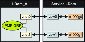
The following diagram shows two virtual networks (vnet1 and vnet2) connected to separate virtual switch instances (vsw0 and vsw1) in the service domain, which, in turn, use two different physical interfaces (e1000g0 and e1000g1). In the event of a physical interface failure, the IP layer in LDom_A detects failure and loss of connectivity on the corresponding vnet through probe-based detection, and automatically fails over to the secondary vnet device.
Figure 7–3 Two Virtual Networks Connected to Separate Virtual Switch Instances

Further reliability can be achieved in the logical domain by connecting each virtual network device (vnet0 and vnet1) to virtual switch instances in different service domains (as shown in the following diagram). In this case, in addition to network hardware failure, LDom_A can detect virtual network failure and trigger a failover following a service domain crash or shutdown.
Figure 7–4 Each Virtual Network Device Connected to Different Service Domains

Refer to the Solaris 10 System Administration Guide: IP Services for more information about how to configure and use IPMP groups.
 Configure a Host Route
If no explicit route is configured for a router in the network corresponding to the IPMP interfaces, then one or more explicit host routes to target systems need to be configured for the IPMP probe-based detection to work as expected. Otherwise, probe detection can fail to detect the network failures.
-
Configure a host route.
# route add -host destination-IP gateway-IP -static
For example:
# route add -host 192.168.102.1 192.168.102.1 -static
Refer to Configuring Target Systems in System Administration Guide: IP Services for more information.
Configuring and Using IPMP in the Service Domain
Network failure detection and recovery can also be set up in a Logical Domains environment by configuring the physical interfaces in the service domain into a IPMP group. To do this, configure the virtual switch in the service domain as a network device, and configure the service domain itself to act as an IP router. (Refer to the Solaris 10 System Administration Guide: IP Services for information on setting up IP routing).
Once configured, the virtual switch sends all packets originating from virtual networks (and destined for an external machine), to its IP layer, instead of sending the packets directly by means of the physical device. In the event of a physical interface failure, the IP layer detects failure and automatically re-routes packets through the secondary interface.
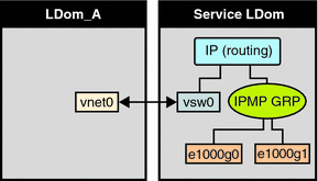
Since the physical interfaces are directly being configured into a IPMP group, the group can be set up for either link-based or probe-based detection. The following diagram shows two network interfaces (e1000g0 and e1000g1) configured as part of an IPMP group. The virtual switch instance (vsw0) has been plumbed as a network device to send packets to its IP layer.
Figure 7–5 Two Network Interfaces Configured as Part of IPMP Group

- © 2010, Oracle Corporation and/or its affiliates
