Link Aggregation Basics
The basic link aggregation topology involves a single aggregation that contains a set of physical interfaces. You might use the basic link aggregation in the following situations:
-
For systems that run an application with distributed heavy traffic, you can dedicate an aggregation to that application's traffic.
-
For sites with limited IP address space that nevertheless require large amounts of bandwidth, you need only one IP address for a large aggregation of interfaces.
-
For sites that need to hide the existence of internal interfaces, the IP address of the aggregation hides its interfaces from external applications.
Figure 6–3 shows an aggregation for a server that hosts a popular web site. The site requires increased bandwidth for query traffic between Internet customers and the site's database server. For security purposes, the existence of the individual interfaces on the server must be hidden from external applications. The solution is the aggregation aggr1 with the IP address 192.168.50.32. This aggregation consists of three interfaces,bge0 through bge2. These interfaces are dedicated to sending out traffic in response to customer queries. The outgoing address on packet traffic from all the interfaces is the IP address of aggr1, 192.168.50.32.
Figure 6–3 Basic Link Aggregation Topology

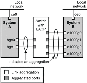
Figure 6–4 depicts a local network with two systems, and each system has an aggregation configured. The two systems are connected by a switch. If you need to run an aggregation through a switch, that switch must support aggregation technology. This type of configuration is particularly useful for high availability and redundant systems.
In the figure, System A has an aggregation that consists of two interfaces, bge0 and bge1. These interfaces are connected to the switch through aggregated ports. System B has an aggregation of four interfaces, e1000g0 through e1000g3. These interfaces are also connected to aggregated ports on the switch.
Figure 6–4 Link Aggregation Topology With a Switch

- © 2010, Oracle Corporation and/or its affiliates
