| Skip Navigation Links | |
| Exit Print View | |

|
Sun Ethernet Fabric Operating System PVRST+ Administration Guide |
| Skip Navigation Links | |
| Exit Print View | |

|
Sun Ethernet Fabric Operating System PVRST+ Administration Guide |
Topology Change and Topology Change Detection
Enable IPv6 Support and Assign IPv6 Addresses
Configure the Spanning-Tree Path Cost
Configure the Spanning Tree Link Type
Configure the Spanning-Tree portfast Setting
Configure Spanning Tree Timers
Display the Spanning Tree Status
Configure the Transmit Hold Count
Configuring Trunk and Access Ports
Configure VLANS and Display the PVRST+ Information for VLANs
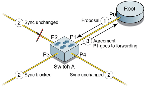
In the spanning tree algorithm, a port selected as a designated port waits two times the fwd-delay rate (that is, 2 x 15 seconds) before transitioning to the forwarding state. In the PVRST+ software, this port corresponds to a designated role and blocking state. This illustration shows the rapid transition of a port to forwarding state.

In the illustration, P0 is a designated port, P1 is the new root port, P2 is an alternate port, P3 is a designated port, and P4 is an edge port. If a new link is created between the root and switch A, then both ports on the link are put in the designated blocking state until the ports receive a BPDU from their counterparts. When a designated port is in discarding or learning state (and only in this state), it sets a proposal bit on the BPDUs it sends out. This situation occurs for port P0 of the root bridge, as shown in Step 1 of the illustration. Because switch A receives superior information, it immediately knows that P1 will be its new root port. Switch A then starts a sync operation to ensure that all of its ports are in-sync with this new information. A port is in-sync if it meets either of these criteria:
Port is in blocking state
Port is an edge port
If an alternate port (P2), a designated forwarding port (P3), and an edge port (P4) already exist on switch A, then P2 and P4 already meet one of the listed criteria. To be in-sync, switch A blocks port P3 by assigning the discarding state to the port. If all of the ports are in-sync, switch A unblocks its newly selected root port (P1) and replies to the root by sending an agreement message (Step 3). This message is a copy of the proposal BPDU with the agreement bit set instead of the proposal bit. Thus, when port P0 receives the agreement, the port knows exactly to which proposal the agreement corresponds.
When P0 receives the agreement, it immediately transits to the forwarding state. In Step 3, port P3, which was left in a designated discarding state after the sync, is in the exact same state as port P0 was in Step 1. Port P3 then starts proposing to its neighbor to quickly transit to forwarding. The handshake mechanism propagates quickly towards the edge of the network, quickly restoring connectivity after a change in the topology.