Part I About This Deployment
This first part of Deployment Example: Single Sign-On, Load Balancing and Failover Using Sun OpenSSO Enterprise 8.0 provides introductory material and an overview of the deployment solution. It contains the following chapters:
Chapter 1 Components and Features
Deployment Example: Single Sign-On, Load Balancing and Failover Using Sun OpenSSO Enterprise 8.0 includes procedures for installing, deploying and configuring a number of host machines and applications. This chapter contains introductory information on the deployment example and includes the following sections:
1.1 Deployment Architecture and Components
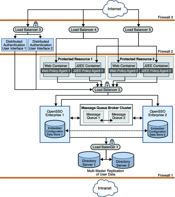
The following graphic illustrates the deployment architecture — where the components will be situated when the deployment is complete. A list of the components that comprise the architecture follows.
Figure 1–1 Deployment Architecture

Note –
Although referred to in the illustration, firewalls are not used in this deployment. For general information on integrating firewalls into this deployment, see 2.5 Firewall Rules.
The following list of components will be installed and configured in using the procedures documented in Part II, Building the Environment.
- Sun OpenSSO Enterprise
-
Two instances of OpenSSO Enterprise provide the core functionality. Each instance is configured with its own embedded configuration data store. Configuration data includes information about services, administrative users, realms, policies, and more. User data is accessed through a single load balancer deployed in front of two instances of Sun Java System Directory Server.
- Distributed Authentication User Interface
-
The Distributed Authentication User Interface is a component of OpenSSO Enterprise that provides a thin presentation layer for user authentication. During user authentication, the Distributed Authentication User Interface interacts with OpenSSO Enterprise to retrieve credentials from the user data store, thus protecting the OpenSSO Enterprise servers from direct user access.
Note –The Distributed Authentication User Interface does not directly interact with the user data store.
- Sun Java System Directory Server
-
Two instances of Directory Server provide storage for the OpenSSO Enterprise user data. User entries will be created for testing this deployment. Both instances of Directory Server are masters that engage in multi-master replication. Multi-master replication allows data to be synchronized in real time between two directories, providing high availability to the OpenSSO Enterprise layer.
Note –The command line is used for all Directory Server configurations in this guide.
- Sun OpenSSO Enterprise Policy Agents 3.0
-
Policy agents are used to restrict access to hosted content or applications. The policy agents intercept HTTP requests from external users and redirect the request to OpenSSO Enterprise for authentication. Web policy agents protect any resources under the doc root of the web container. J2EE policy agents protect a variety of hosted J2EE applications; in this deployment, agentsample is used. The agents communicate with the OpenSSO Enterprise instances through one of two configured load balancers.
- Protected Resource Host Machines
-
The protected resources host machines contain the content for which access is restricted. Towards this end, web servers, application servers and policy agents will be installed. Two load balancers are configured in front of the host machines to balance traffic passing through the policy agents.
- Sun Java System Message Queue
-
OpenSSO Enterprise uses two instances of Message Queue to form a cluster for distributing client connections and delivering messages. The Berkeley Database by Sleepycat Software, Inc. is the session store database. When an instance of OpenSSO Enterprise goes down and session failover is enabled, the user's session token can be retrieved from one of the Message Queues by the available instance of OpenSSO Enterprise. This ensures that the user remains continuously authenticated, allowing access to the protected resources without having to reauthenticate.
- Load Balancers
-
The load balancer hardware and software used for this deployment is BIG-IP® manufactured by F5 Networks. They are deployed as follows:
Distributed Authentication User Interface Load Balancer. This external-facing load balancer exposes the remote, web-based Distributed Authentication User Interface for user authentication and self-registration.
OpenSSO Enterprise Load Balancer. This internal-facing load balancer exposes the web-based OpenSSO Enterprise console to internal administrators. Alternatively, internal administrators can bypass this load balancer and log in directly.
J2EE Policy Agents Load Balancer. The load balancer in front of the J2EE policy agents installed on the Protected Resource machines provides round-robin load balancing and a single virtual server by balancing traffic passing through the agents.
Web Policy Agents Load Balancer. The load balancer in front of the web policy agents installed on the Protected Resource machines provides round-robin load balancing and a single virtual server by balancing traffic passing through the agents.
Directory Server Load Balancer. The load balancer in front of the Directory Server instances provide round-robin load balancing and a single virtual Directory Server host name for the instances of OpenSSO Enterprise. It detects individual Directory Server failures and recoveries, taking failed servers off the load balancer list.
Note –In this Deployment Example, we use BIG-IP and it's supported passive-cookie mechanism to address session persistence with the backend OpenSSO Enterprise servers. The intent is to enable persistence of requests to the backend servers depending upon the value of amlbcookie, the OpenSSO Enterprise cookie. Stickiness can then be maintained for all OpenSSO Enterprise related requests from browsers or agents. Different load balancers might support different mechanisms to achieve session persistence. It is the responsibility of the end users to determine and map this functionality to their own choice of load balancer.
1.2 Key Features of Deployment
-
All components (including installations of OpenSSO Enterprise and Directory Server, the Distributed Authentication User Interface, and policy agents) are redundant to achieve high availability.
-
All components use ZIP-based installation.
-
All components use load-balancing for session failover and high performance.
-
Each instance of OpenSSO Enterprise is installed with an embedded configuration data store.
-
Each instance of Directory Server contains am-users to serve as the user data store.
-
OpenSSO Enterprise instances are configured to run as non-root users.
-
The environment is configured for system failover capability, ensuring that when one instance of OpenSSO Enterprise goes down, requests are redirected to the second instance.
 Caution –
 It is important to note that system failover, by itself, does not ensure OpenSSO Enterprise session failover which is configured separately.
-
The environment is configured for session failover capability. Session failover ensures that when the instance of OpenSSO Enterprise where the user's session was created goes down, the user's session token can still be retrieved from a backend session database. Thus, the user is continuously authenticated, and does not have to log into the system again unless the session is invalidated as a result of logout or session expiration.
-
Communications to the OpenSSO Enterprise load balancer, to the Distributed Authentication User Interface load balancer, and to the Directory Server load balancer are in Secure Sockets Layer (SSL).
-
Policy agents are configured with a unique agent profile to authenticate to OpenSSO Enterprise.
-
The Distributed Authentication User Interface uses a custom user profile to authenticate to OpenSSO Enterprise instead of the default amadmin or UrlAccessAgent.
1.3 Sequential Component Interactions
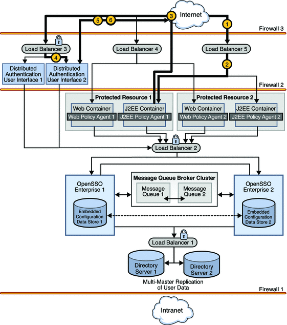
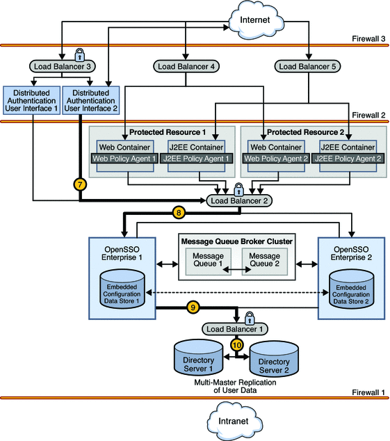
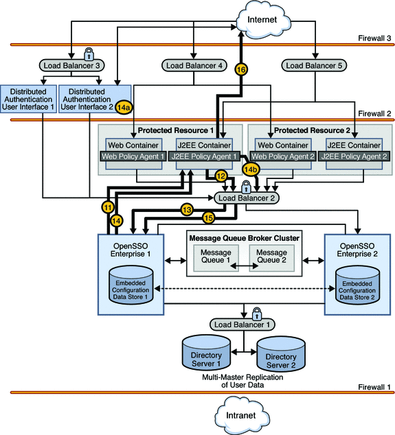
The following sequence describes the interactions between the various components in this deployment. The interactions are illustrated and the numbered steps correspond to the numbers in the diagrams.
-
A user attempts to access a J2EE application hosted on both Protected Resource 1 and Protected Resource 2.

-
Load Balancer 5 directs the user to Protected Resource 1 where J2EE Policy Agent 1 intercepts the request.
-
J2EE Policy Agent 1 checks for an OpenSSO Enterprise cookie (SSOToken). In this scenario, no cookie is found and the request is returned to the browser which redirects the request to Load Balancer 3, the load balancer for the instances of the Distributed Authentication User Interface.
-
Load Balancer 3 routes the user request to Distributed Authentication User Interface 2.
-
Distributed Authentication User Interface 2 displays a login page to the user.
-
The user enters credentials on the login page which are returned to Distributed Authentication User Interface 2.
-
Distributed Authentication User Interface 2 passes the credentials to Load Balancer 2.

-
Load Balancer 2 routes the credentials to OpenSSO Enterprise 1.
-
OpenSSO Enterprise 1 sends a request for validation of the credentials to Load Balancer 1 in front of the Directory Server instances.
-
Load Balancer 1 routes the request to Directory Server 2.
-
Authentication occurs using the Distributed Authentication User Interface. Assuming successful authentication, OpenSSO Enterprise Distributed Authentication User Interface 1 sends the response back to J2EE Policy Agent 1 which receives the request and checks again for the OpenSSO Enterprise cookie.

-
When a cookie is found, J2EE Policy Agent 1 sends a session validation request to the OpenSSO Enterprise Load Balancer 2.
-
The OpenSSO Enterprise Load Balancer 2 forwards the request to OpenSSO Enterprise 1 where the session originated. Cookie-based persistency enables proper routing.
-
OpenSSO Enterprise 1 sends a response back to J2EE Policy Agent 1.
-
If the session is not valid, J2EE Policy Agent 1 redirects the user back to Distributed Authentication User Interface 2.
-
If the session is valid, J2EE Policy Agent 1 receives the response and sends a request for policy evaluation to Load Balancer 2.
-
-
As the session is valid, the request is directed to OpenSSO Enterprise 1 to conduct the policy evaluation.
-
Based on the outcome of the policy evaluation, J2EE Policy Agent 1 allows or denies access to the resource. In this scenario, the user is allowed access.
Chapter 2 Technical Overview
This chapter contains technical information regarding the machines, software, and other components used in this deployment example. It contains the following sections:
2.1 Host Machines
The following table lists the attributes of the host machines used for this deployment example.
Table 2–1 Host Machines and Operating Systems|
Host Machine |
Architecture |
Operating System |
|---|---|---|
|
da–1 |
SPARC |
Solaris 10 |
|
da–2 |
SPARC |
Solaris 10 |
|
ds–1 |
x86 |
Solaris 10 |
|
ds–2 |
x86 |
Solaris 10 |
|
mq–1 |
x86 |
Solaris 10 |
|
mq-2 |
x86 |
Solaris 10 |
|
osso–1 |
SPARC |
Solaris 10 |
|
osso–2 |
SPARC |
Solaris 10 |
|
pr–1 |
SPARC |
Solaris 10 |
|
pr–2 |
SPARC |
Solaris 10 |
2.2 Software
The following table lists the software used in this deployment example.
Table 2–2 Software and Download Locations|
Product |
Version |
Download Location |
|---|---|---|
|
Sun OpenSSO Enterprise |
8.0 | |
|
Sun Java System Web Server |
7.0 Update 3 | |
|
Sun Java System Application Server |
9.1 Update 1 | |
|
Sun Java System Directory Server |
6.1 | |
|
BEA Weblogic Server |
10 | |
|
Web Policy Agent (for Sun Java System Web Server) |
3.0 | |
|
J2EE Policy Agent (for Sun Java System Application Server and BEA Weblogic Server) |
3.0 | |
|
Java (for OpenSSO Enterprise and policy agents) |
1.5.0_09 | |
|
BIG-IP Load Balancer |
4.5.10 |
2.3 Main Service URLs
The following table summarizes the main service URLs for the components used in this deployment example. For detailed configuration information, see Part III, Reference: Summaries of Server and Component Configurations.
Table 2–3 Components and Main Service URLs|
Components |
Main Service URL |
|
|---|---|---|
|
Directory Server Instances and Load Balancers |
||
|
Directory Server 1 |
ldaps://ds-1.example.com:1736 (for monitor node) ldaps://ds-1.example.com:1736 (for user data) |
|
|
Directory Server 2 |
ldaps://ds-2.example.com:1736 (for monitor node) ldaps://ds-2.example.com:1736 (for user data) |
|
|
Load Balancer 1 |
ldaps://lb-1.example.com:489 (for user data) |
|
|
OpenSSO Enterprise Instances and Load Balancer |
||
|
OpenSSO Enterprise 1 |
https://osso-1.example.com:1081 (for monitor node) https://osso-1.example.com:1081/opensso/console |
|
|
OpenSSO Enterprise 2 |
https://osso-2.example.com:1081 (for monitor node) https://osso-2.example.com:1081/opensso/console |
|
|
Load Balancer 2 |
https://lb-2.example.com:1081 |
|
|
Distributed Authentication User Interfaces and Load Balancer |
||
|
Distributed Authentication User Interface 1 |
https://da-1.example.com:1443 (for monitor node) https://da-1.example.com:1443/distAuth/ (for users) |
|
|
Distributed Authentication User Interface 2 |
https://da-2.example.com:1443 (for monitor node) https://da-2.example.com:1443/distAuth/ (for users) |
|
|
Load Balancer 3 |
https://lb-3.example.com:1443 (secure port) |
|
|
Protected Resources 1 and 2: Web Containers, Policy Agents and Load Balancers |
||
|
Web Container 1 |
https://pr-1.example.com:8989 (for Sun Java System Web Server administration console) |
|
|
Web Policy Agent 1 |
http://pr-1.example.com:1080 |
|
|
J2EE Container 1 |
http://pr-1.example.com:7001/console (for BEA Weblogic administration server) |
|
|
J2EE Policy Agent 1 |
http://pr-1.example.com:1081/agentapp |
|
|
Web Container 2 |
https://pr-2.example.com:8989 (for Sun Java System Web Server administration console) |
|
|
Web Policy Agent 2 |
http://pr-2.example.com:1080 |
|
|
J2EE Container 2 |
http://pr-2.example.com:7001/console (for BEA WebLogic administration server) |
|
|
J2EE Policy Agent 2 |
http://pr-2.example.com:1081/agentapp |
|
|
Policy Agent Load Balancers |
||
|
Load Balancer 4 |
http://lb-4.example.com:90 (for web policy agents) |
|
|
Load Balancer 5 |
http://lb-5.example.com:91 (for J2EE policy agents) |
|
|
Message Queue Broker Instances |
||
|
Message Queue 1 |
http://mq-1.example.com:7777 |
|
|
Message Queue 2 |
http://mq-2.example.com:7777 |
|
2.4 Intercomponent Communication
The following table provides an overview of the types of communication that take place between servers, load balancers, and other components in the deployment example.
Table 2–4 Summary of Intercomponent Communication|
Entity A |
Entity B |
Bi-Directional |
Port |
Protocol |
Traffic Type |
|---|---|---|---|---|---|
|
Internet Users |
Load Balancer 4 |
90 |
HTTP |
Application Traffic |
|
|
Internet Users |
Load Balancer 5 |
91 |
HTTP |
Application Traffic |
|
|
Internet Users |
Load Balancer 3 |
1443 |
HTTPS |
Internet User Authentication |
|
|
Load Balancer 3 |
Distributed Authentication User Interface 1 |
1443 |
HTTPS |
Internet User Authentication |
|
|
Load Balancer 3 |
Distributed Authentication User Interface 2 |
1443 |
HTTPS |
Internet User Authentication |
|
|
Load Balancer 4 |
Protected Resource 1 |
1080 |
HTTP |
Application Traffic |
|
|
Load Balancer 4 |
Protected Resource 2 |
1080 |
HTTP |
Application Traffic |
|
|
Load Balancer 5 |
Protected Resource 1 |
1081 |
HTTP |
Application Traffic |
|
|
Load Balancer 5 |
Protected Resource 2 |
1081 |
HTTP |
Application Traffic |
|
|
Distributed Authentication User Interface 1 |
Load Balancer 2 |
1081 |
HTTPS |
Internet User Authentication |
|
|
Distributed Authentication User Interface 2 |
Load Balancer 2 |
1081 |
HTTPS |
Internet User Authentication |
|
|
Protected Resource 1 |
Load Balancer 2 |
1081 |
HTTPS |
Agent - OpenSSO Enterprise communication |
|
|
Protected Resource 2 |
Load Balancer 2 |
1081 |
HTTPS |
Agent - OpenSSO Enterprise communication |
|
|
Load Balancer 3 |
OpenSSO Enterprise 1 |
1081 |
HTTPS |
Agent - OpenSSO Enterprise communication for authentication |
|
|
Load Balancer 3 |
OpenSSO Enterprise 2 |
1081 |
HTTPS |
Agent - OpenSSO Enterprise communication for authentication |
|
|
OpenSSO Enterprise 1 |
OpenSSO Enterprise 2 |
Yes |
1081 |
HTTPS |
Back-channel communication |
|
OpenSSO Enterprise 1 |
Message Queue 1 |
7777 |
HTTP |
Session communication |
|
|
OpenSSO Enterprise 1 |
Load Balancer 1 |
489 |
LDAPS |
User profile communication for authentication |
|
|
OpenSSO Enterprise 2 |
Message Queue 2 |
7777 |
HTTP |
Session communication |
|
|
OpenSSO Enterprise 2 |
Load Balancer- 2 |
489 |
LDAPS |
User profile communication for authentication |
|
|
Message Queue 1 |
Message Queue 2 |
Yes |
7777 |
HTTP |
Session communication |
|
Message Queue 2 |
Message Queue 1 |
Yes |
7777 |
HTTP |
Session communication |
|
Load Balancer 1 |
Directory Server 1 |
1736 |
LDAPS |
User profile communication for authentication |
|
|
Load Balancer 1 |
Directory Server 2 |
1736 |
LDAPS |
User profile communication for authentication |
|
|
Directory Server 1 |
Directory Server 2 |
Yes |
1489 |
LDAP |
Data replication communication |
|
Directory Server 2 |
Directory Server 1 |
Yes |
1489 |
LDAP |
Data replication communication |
2.5 Firewall Rules
Actual firewalls are not set up in this deployment example. If firewalls were deployed they would protect critical components using three distinct security zones as illustrated in 1.1 Deployment Architecture and Components. One zone is completely secure, protected by all three firewalls, and used for internal traffic only. The second, less secure zone is protected by only two firewalls but is also for internal traffic only. The third, minimally-secured demilitarized zone (DMZ) leaves only simple components and interfaces exposed to the Internet and is used for external traffic. Thus, direct access to individual instances of OpenSSO Enterprise and Directory Server is allowed only if permitted by firewall rules. Based on the illustration cited:
-
The instances of OpenSSO Enterprise are isolated between an internal firewall and the DMZ, and exposed through an external-facing load balancer. The load balancer and instances together provide high data availability within the infrastructure.
-
The policy agents themselves are deployed behind a load balancer configured in the DMZ.
-
The Distributed Authentication User Interface would be deployed in the DMZ for communication with OpenSSO Enterprise behind a firewall, additionally protecting the OpenSSO Enterprise instances from exposure in the minimally-secured DMZ.
You may set up firewalls to allow traffic to flow as described in the following table.
Table 2–5 Summary of Firewall Rules|
From |
To |
Port # |
Protocol |
Traffic Type |
|---|---|---|---|---|
|
Internet users |
Load Balancer 3 |
1443 |
HTTPS |
User authentication |
|
Internet users |
Load Balancer 4 |
90 |
HTTP |
Application access by internet user |
|
Internet users |
Load Balancer 5 |
91 |
HTTP |
Application access by internet user |
|
Distributed Authentication User Interface 1 |
Load Balancer 2 |
1081 |
HTTPS |
User authentication |
|
Distributed Authentication User Interface 2 |
Load Balancer 2 |
1081 |
HTTPS |
User authentication |
|
Load Balancer 4 |
Protected Resource 1 |
1080 |
HTTP |
Application access by user |
|
Load Balancer 5 |
Protected Resource 2 |
1081 |
HTTP |
Application access by user |
2.6 Viewing Replicated Entries
Throughout this deployment example, we use ldapsearch to view replicated entries. An alternative would be to enable the Directory Server audit log and run tail -f. Enabling the audit log will also help to track changes and updates made during OpenSSO Enterprise configuration.
Chapter 3 Before You Begin
This chapter contains information you need to know before beginning the documented installation and configuration procedures. It contains the following sections:
3.1 Technical Reference
See Chapter 2, Technical Overview for a quick reference of host machines, port numbers, operating systems, naming conventions, and component names used in this deployment example. See Part III, Reference: Summaries of Server and Component Configurations for more detailed information.
3.2 Setting Up the Load Balancers
The load balancer hardware and software used in this deployment environment is BIG-IP® manufactured by F5 Networks. If you are using different load balancer software, see the documentation that comes with that product for detailed settings information. This document assumes that you have already installed the required load balancers. The following sections require load-balancing hardware and software.
3.3 Obtaining Secure Socket Layer Certificates
In order to enable secure communications using the Secure Sockets Layer (SSL) protocol you need to obtain root certificates and server certificates from a certificate authority (CA). A CA root certificate proves that the particular CA issued a particular server certificate. CA root certificates are publicly available. The root certificate used in this deployment is a test certificate issued by OpenSSL and named ca.cer. You can obtain a root certificate from any commercial certificate issuer such as VeriSign, Thawte, Entrust, or GoDaddy.
The server certificates are requested within each procedure. You should know how to request server certificates from your CA of choice before beginning a deployment. The following sections are related to requesting, installing, and importing root and server certificates:
-
To Install a Root Certificate and a Server Certificate on Directory Server 1
-
To Install a Root Certificate and a Server Certificate on Directory Server 2
-
To Install Application Server on the OpenSSO Enterprise 1 Host Machine
-
To Install Application Server on the OpenSSO Enterprise 2 Host Machine
-
To Request a Certificate for the OpenSSO Enterprise Load Balancer
-
To Install a CA Root Certificate to the OpenSSO Enterprise Load Balancer
-
To Install the Server Certificate to the OpenSSO Enterprise Load Balancer
-
To Request and Install a Server Certificate and a Root Certificate for Web Server 1
-
To Request and Install a Server Certificate and a Root Certificate for Web Server 2
-
To Import the Root Certificate to the Web Server 1 JDK Certificate Store
-
To Import the Root Certificate to the Web Server 2 JDK Certificate Store
-
To Request a Certificate for the Distributed Authentication User Interface Load Balancer
-
To Import a Root Certificate to the Distributed Authentication User Interface Load Balancer
-
To Import a Certificate to the Distributed Authentication User Interface Load Balancer
3.4 Resolving Host Names
There are many ways to resolve the host names used in this deployment. You may use a DNS naming service, or you can map IP addresses to host names in the local host file on all UNIX® hosts. The same entries must also be added to equivalent files on Windows hosts, and on client machines where browsers are used. For example:
1xx.xx.xx.x1 DirectoryServer-1 ds-1.example.com 1xx.xx.xx.x2 DirectoryServer-2 ds-2.example.com 1xx.xx.xx.x3 OpenSSO-1 osso-1.example.com 1xx.xx.xx.x4 OpenSSO-2 osso-2.example.com |
3.5 Known Issues and Limitations
See Appendix F, Known Issues and Limitations for descriptions of problems you may encounter when implementing the deployment example. This list will be updated as new information becomes available.
Although the instructions and procedures documented in this book incorporate many best practices, and may be suitable in many different scenarios, this is not the only way to achieve the same results. If you plan to deviate from the task sequence or details described, you should refer to the relevant product documentation for information on differences in platforms, software versions or other requirement constraints.
- © 2010, Oracle Corporation and/or its affiliates
